Jacobsen STEINER 75-70710 Setup guide

WARNING: If incorrectly used this machine can cause severe injury. Those who use
and maintain this machine should be trained in its proper use, warned of its dangers
and should read the entire manual before attempting to set up, operate, adjust or
service the machine.
OWNER/OPERATOR’SMANUAL
& ILLUSTRATED PARTS LIST
09-156 REV A
MODEL:
75-70710 TRACTOR CAB 420/430 CB420

CALIFORNIA
Proposition 65 Warning
Diesel engine exhaust and some of
its constituents are known to the State
of California to cause cancer, birth
defects and other reproductive harm.
Californie Proposition 65
Avertissement
Les échappements des moteurs diesel
et certains de leurs composés sont
reconnus par l’Etat de Californie pour
être cancérigènes, provoquer des
défauts congénitaux et d’autres dangers
en matière de reproduction.
ADVERTENCIA
AVERTISSEMENT
WARNING
The engine exhaust from this product
contains chemicals known to the State
of California to cause cancer, birth
defects or other reproductive harm.
California Advertencia
de la Proposicion 65
El estado de California hace saber que
los gases de escape de los motores
diesel y algunos de sus componentes
producen cáncer, defectos de
nacimiento y otros daños en el
proceso de reproducción humana.
L’
é
mission du moteur de ce mat
é
riel
contient des produits chimiques que
l’Etat de Californie consid
è
re
ê
tre
canc
é
rig
è
nes, provoquer des d
é
fauts
cong
é
nitaux et d’autres dangers en
mati
è
re de reproduction.
El estado de California hace saber
que los gases de escape de este
producto contienen productos
quÍmicos que producen cáncer,
defectos de nacimiento y otros daños
en el proceso de reproducción
humana.
© 2003, TEXTRON INC

1
TRACTOR
CAB
IMPORTANTMESSAGE
Thank you for purchasing this Jacobsen product. You have purchased a world class product, one of the best
designed and built anywhere.
This product comes with an Owner/Operator's Manual. The useful life and good service you receive from this
product depends to a large extent on how well you read and understand this manual. Treat this product properly
and adjust it as instructed, and it will give you many years of reliable service.
See a Jacobsen dealer for any service or parts needed. Jacobsen service ensures that you continue to receive
the best results possible from Jacobsen products. You can trust Jacobsen replacement parts because they are
manufactured with the same high precision and quality as the original parts.
Jacobsen designs and builds its equipment to serve many years in a safe and productive manner. For longest
life, use this product only as directed in the manual, keep it in good repair and follow safety warnings and
instructions. You'll always be glad you did.
Jacobsen, a Textron Company
One Bob Cat Lane
Johnson Creek, WI 53038-0469
9-2003
TABLE OF CONTENTS FIGURES PAGE
INTRODUCTION ........................................................................................................................................... 2
SPECIFICATIONS ......................................................................................................................................... 3
SAFETY ..................................................................................................................................................... 4, 5
ASSEMBLY INSTRUCTIONS ..................................................................................................................... 6-9
INSTALLATION ............................................................................................................................................ 10
REMOVAL.....................................................................................................................................................11
CAB PARTS ....................................................... FIGURE 1 ................................................................. 12, 13
2
TRACTOR
CAB
INTRODUCTION
DESCRIPTION
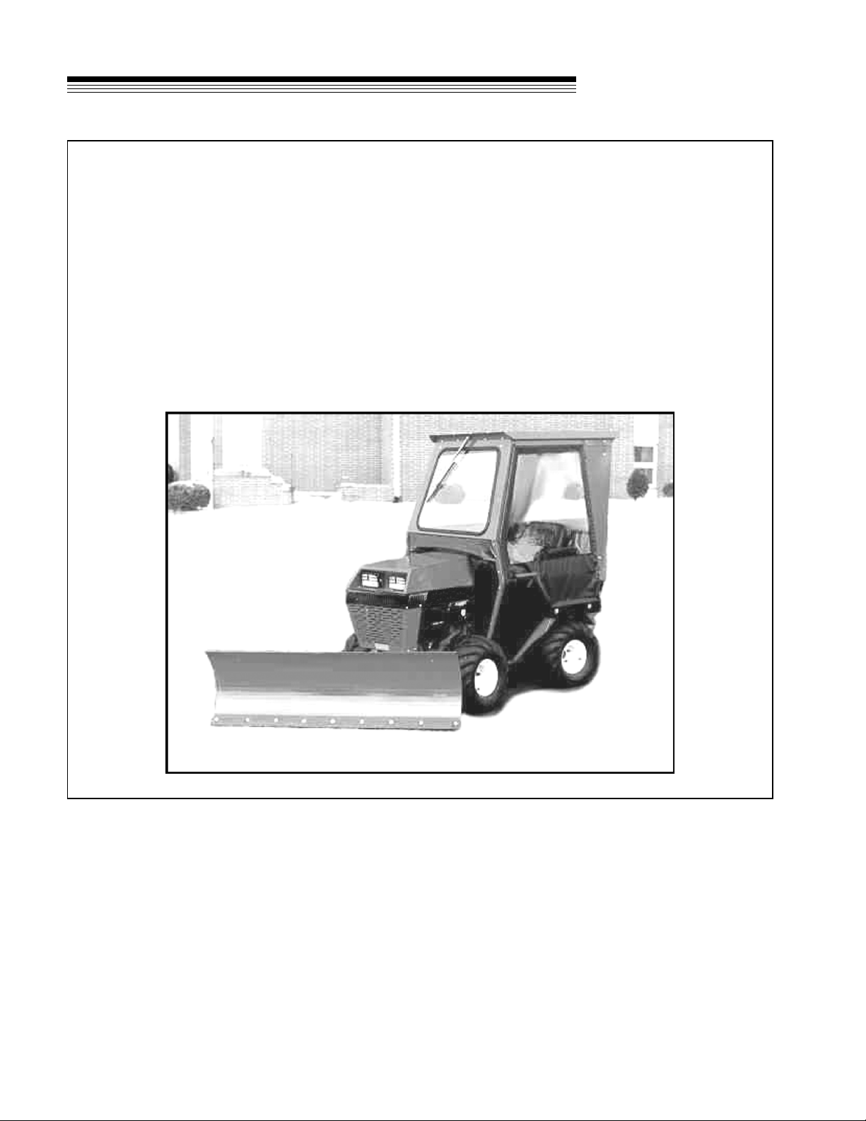
The sturdy CB420 cab is carefully designed to fit the model 420 and 430 tractor equipped with a
ROPS rollbar. It is extremely useful in cold weather when operating a snowblower, V-blade, or a power
angle blade. Exceptional features include ease of entry from either side, full glass windshield and back
window, and lightweight removable doors. Supported by the ROPS rollbar and equipped with a seat belt,
the operator has added comfort and safety protection. There are a few limitations, however, with the cab
installed. Overall visibility is good, but portions of the cab create blind spots.
A windshield wiper is standard equipment. Additional lights and safety lights may be added as desired by
the owner.
NOTE: The CB420 cab cannot be used with the front end loader, vertical auger or boom mower
attachments when the mounting shaft is in place.

3
TRACTOR
CAB
SPECIFICATIONS
Overall Height - Installed .......................................................................................68"
Overall Width .........................................................................................................45"
Cab Length ............................................................................................................48"
Head Room............................................................................................................40"
Inside Roof Width ..................................................................................................30"
Roof Length ...........................................................................................................42"
Roof Width (outside)..............................................................................................35"
SPECIFICATIONS

4
TRACTOR
CAB
SAFETY
NOTICE !!!
Unauthorized modifications may present extreme
safety hazards to operators and bystanders and
could also result in product damage.
Jacobsen, a Textron Company strongly warns
against, rejects and disclaims any modifications,
add-on accessories or product alterations that are
not designed, developed, tested and approved by
Jacobsen Engineering Department. Any Jacobsen
product that is altered, modified or changed in any
manner not specifically authorized after original
manufacture–includingtheadditionof“after-market”
accessories or component parts not specifically
approved by Jacobsen–will result in the Jacobsen
Warranty being voided.
Anyandallliabilityforpersonalinjuryand/orproperty
damagecausedbyanyunauthorizedmodifications,
add-on accessories or products not approved by
Jacobsen will be considered the responsibility of
the individual(s) or company designing and/or
making such changes. Jacobsen will vigorously
pursuefullindemnification and costs fromany party
responsibleforsuchunauthorizedpost-manufacture
modifications and/or accessories should personal
injury and/or property damage result.
This symbol means:
ATTENTION!
BECOME ALERT!
Your safety and the safety of others is involved.
Signal word definitions:
The signal words below are used to identify levels
of hazard seriousness. These words appear in this
manual and on the safety labels attached to
Jacobsenmachines.Foryoursafetyandthesafety
ofothers,readandfollowtheinformationgivenwith
thesesignalwordsand/orthesymbolshownabove.
DANGER indicates an imminently hazardous
situationwhich, if notavoided, WILL result in death
or serious injury.
WARNING indicates a potentially hazardous
situation which, if not avoided, COULD result in
death or serious injury.
CAUTION indicates a potentially hazardous
situation which, if not avoided, MAY result in minor
or moderate injury. It may also be used to alert
against unsafe practices or property damage.
CAUTION used without the safety alert symbol
indicates a potentially hazardous situation which, if
not avoided, MAY result in property damage
MODEL NUMBER: This number appears on
sales literature, technical manuals and price
lists.
SERIAL NUMBER: This number appears only
on your mower. It contains the model number
followed consecutively by the serial number.
Use this number when ordering parts or seeking
warranty information.

5
TRACTOR
CAB SAFETY
1. Read and understand the Owner’s Manual before attempting to operate this machine.
2. Operate all controls from the operator’s seat. NO RIDERS.
3. Keep all shields in place and safety switches adjusted properly.
4. Do not leave equipment unattended. STOP the engine and remove the key.
5. Do not allow minors or the inexperienced to operate this machine.
6. Keep people and pets a safe distance away from machine using power driven attachments. Injury
could result from flying debris.
GENERALSAFETY
OPERATINGSAFETY
1. DO NOT attempt to work on unit or any
attachments with the engine running.
STOP ENGINE!
2. Before leaving operator's seat:
•Lower attachments
• Stop PTO driven units
• Set PARKING brake
• Stop engine.
6
TRACTOR
CAB
ASSEMBLY INSTRUCTIONS
1. Have a ROPS approved roll bar and seat belt
mounted to your tractor, using the roll bar
instructions.
NOTE: If you have a canopy on the roll bar, it
needs to be removed.
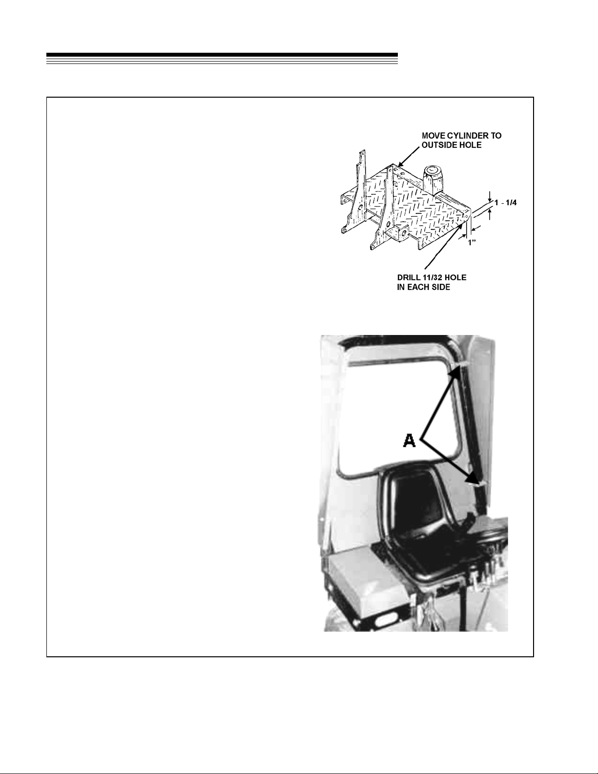
2. (420 only, if applicable) Move steering cylinder
mount on the treadplate to the outside hole.
THIS IS VERY IMPORTANT! (See Drawing A)
3. Open the hardware package and sort the bolts
and nuts according to size.
4. Slide the rear panel over the roll bar and fasten
with (4) “W” shaped clamps Aand (8)
5/16 X 1" bolts. Leave bolts loose at this time.
5. Lay the roof panel in place and bolt to the rear
panel with (9) 5/16 X 3/4" bolts.
NOTE: The rear panel may need to be moved to fit
roof panel as shown in Photo 3 Page 7.
6. Drill (2) 11/32" holes in the front corners of the
tread plate as shown in Drawing A.
Drawing A
Photo 1
7
TRACTOR
CAB ASSEMBLY INSTRUCTIONS
7. Set the front panel on the tractor and insert two
5/16 X 1" bolts through the frame and
treadplate. Next, bolt the top of the front panel
to the front of the roof panel as shown.
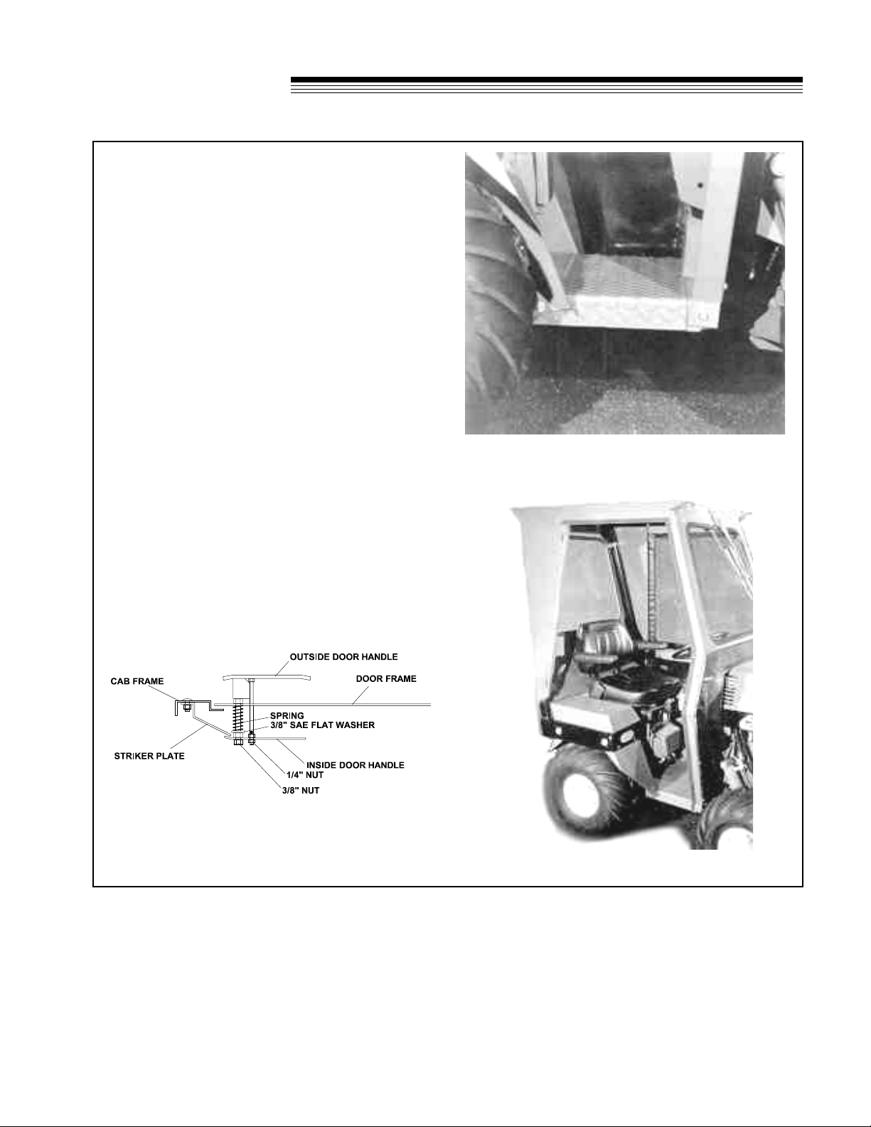
8. Bolt the four hinges to the rear panel with (8)
5/16 X 3/4" bolts as shown in Photo 3.
9. Tighten all bolts that have been installed at this
time. Install weatherstrip around the door
opening along the top and front sides as shown
in Photo 3.
10. Attach striker plate to cab frame as shown in
Drawing B. Install door on hinges. Assemble
latch to door as shown in Drawing B. Adjust
striker plate forward or back to provide the
inside handle to catch approximately 1/2".
Adjust the tightness of the latch by adjusting the
3/8" and 1/4" nuts in or out. In a few cases the
striker plate may need to be bent slightly.
NOTE: Doors may require bending slightly for best
fit.
Drawing B
Photo 2
Photo 3
8
TRACTOR
CAB
ASSEMBLY INSTRUCTIONS
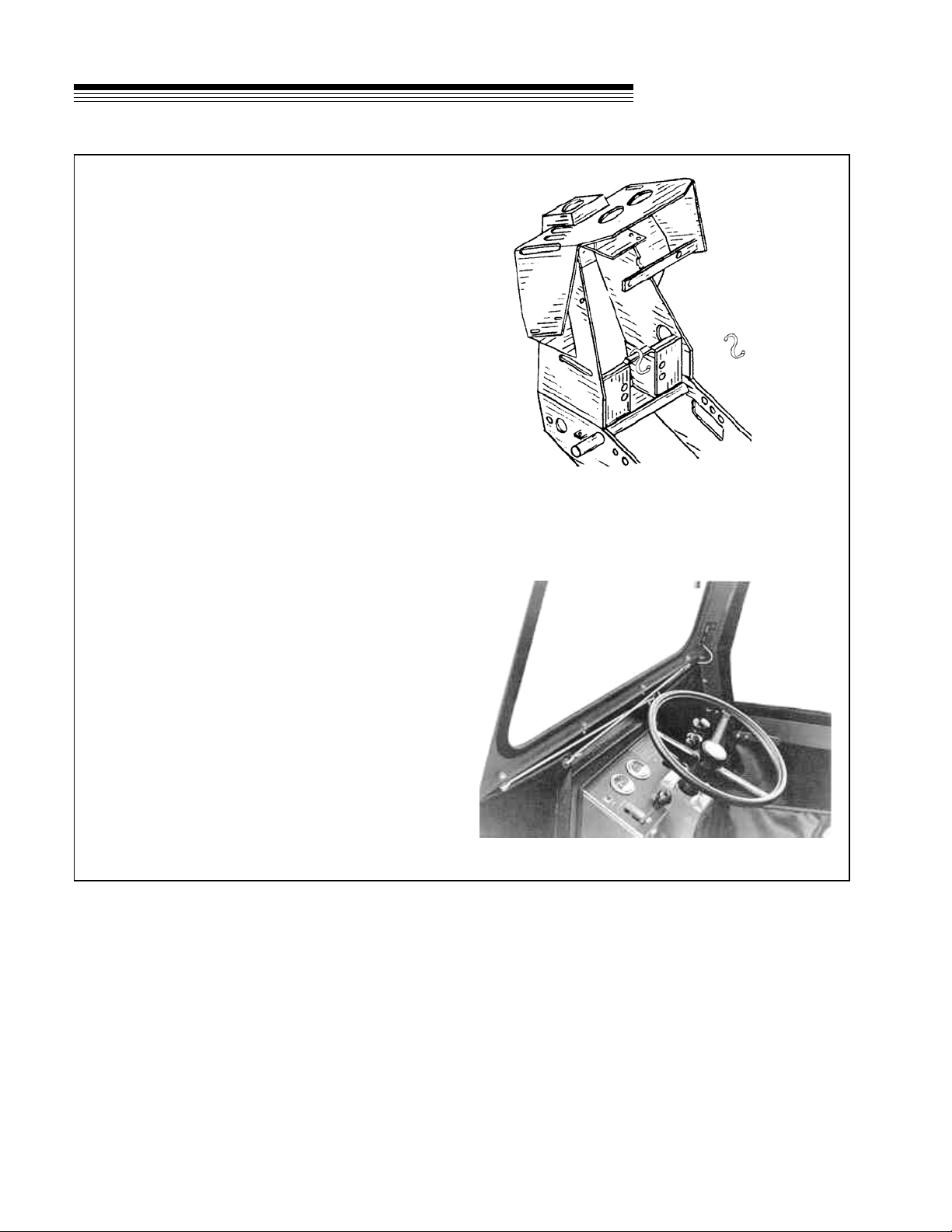
11. From the left side of the tractor, install the “S”
hook on the top edge of the pump mount plate
as shown in Drawing C.
12. Stretch each top elastic cord from the fabric
panel across the front panel to the extended
bolts. Pull the middle elastic cord through the
tractor above the drive shaft. Loop the elastic
cord over the “S” hook to prevent rubbing the
driveshaft. Take the bottom elastic cord through
to the other side in front of the frame pivot as
shown Photo 4.
13. Mount the wiper above the windshield according
to the wiper instructions. Mount the wiper blade
on the wiper arm with the short end of the blade
away from the wiper motor. Check the wiper
blade path so that it does not contact the rubber
moulding. Fasten the inline fuse to the auxiliary
side of the circuit breaker and route the wire to
the wiper.
14. On Kubota engine models, install the air intake
tube guard on the left rear of the black side
panel. The guard bolts to the same holes that
the side panel does and uses the existing
hardware. The guard is to prevent the cab
fabric from plugging the air intake tube and
stalling the engine.
Drawing C
Photo 4
(420 is shown.......430 is similar)
This manual suits for next models
1
Table of contents
Other Jacobsen Tractor manuals

Jacobsen
Jacobsen Groom Master II 88009 User manual

Jacobsen
Jacobsen G-10 Installation and maintenance instructions

Jacobsen
Jacobsen AR250 TURBO User manual

Jacobsen
Jacobsen Groom Master II Guide

Jacobsen
Jacobsen HR3300T Guide

Jacobsen
Jacobsen Groom Master II 88009 User manual

Jacobsen
Jacobsen Groom Master II Guide


