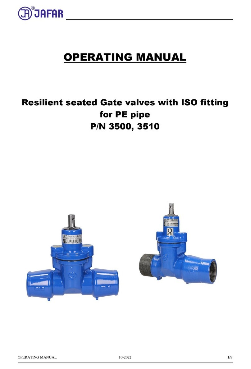
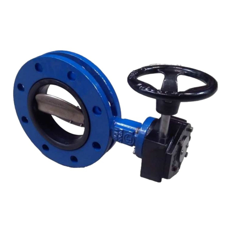
Jafar 5220 User manual

OPERATION AND MAINTENANCE MANUAL 01-2016
1
Operation and maintenance
manual for
BALL
VALVES
P/N
5220
5320
5321
Approved for use by
President of Factory, JAFAR S.A.
Failure to comply with the guidelines and instructions in this Operation and
Maintenance Manual releases the manufacturer from all obligations, liability and guarantee.
Due to continuous business development, we reserve the right to introduce
modifications and design changes to the presented product.

OPERATION AND MAINTENANCE MANUAL 01-2016
2
CONTENTS
1 TECHNICAL DESCRIPTION........................................................................................................................... 3
1.1 PRODUCT DESIGNATION AND IDENTIFICATION.............................................................................. 3
1.2 USE............................................................................................................................................................... 3
1.3 TECHNICAL SPECIFICATION.................................................................................................................. 3
2 DESIGN.............................................................................................................................................................. 5
2.1 DESCRIPTION OF THE VALVE DESIGN................................................................................................ 5
2.2 MATERIALS................................................................................................................................................ 5
2.3 DIMENSIONS.............................................................................................................................................. 7
2.4 REFERENCE STANDARDS..................................................................................................................... 10
2.5 ORDERING INFORMATION................................................................................................................... 10
2.6 PRODUCTION AND ACCEPTANCE ...................................................................................................... 11
2.7 MARKINGS ............................................................................................................................................... 11
3 PROTECTION, STORAGE & TRANSPORT ................................................................................................. 11
3.1 PROTECTIVE COATINGS....................................................................................................................... 11
3.2 PACKAGING............................................................................................................................................. 11
3.3 STORAGE.................................................................................................................................................. 11
3.4 TRANSPORT ............................................................................................................................................. 11
4 ASSEMBLY AND INSTALLATION............................................................................................................... 12
4.1 ASSEMBLY GUIDELINES....................................................................................................................... 12
4.2 ASSEMBLY INSTRUCTIONS.................................................................................................................. 12
4.3 OPERATION.............................................................................................................................................. 15
4.4 OCCUPATIONAL HEALTH AND SAFETY........................................................................................... 15
5 WARRANTY TERMS AND CONDITIONS ................................................................................................... 15

OPERATION AND MAINTENANCE MANUAL 01-2016
3
1 TECHNICAL DESCRIPTION
1.1 PRODUCT DESIGNATION AND IDENTIFICATION
The subject of this Operation and Maintenance Manual is:
Flanged ball valve
TYPE 5220
- full bore design
- stainless steel free-floating ball (closure)
- stainless steel spindle
- spindle seal
- closure soft sealing
- sectional design
- optional drive actuator ready
TYPE 5320
- reduced bore design
- stainless steel free-floating ball (closure)
- stainless steel spindle
- spindle seal
- closure soft sealing
- monolithic design
- optional drive actuator ready
TYPE 5321
- reduced bore design
- stainless steel free-floating ball (closure)
- stainless steel spindle
- spindle seal
- closure soft sealing
- monolithic design
- optional drive actuator ready
1.2 USE
The TYPE 5220 & 5320 flanged and TYPE 5321 welded ends ball valves are intended for isolation of medium
flow in industrial systems, heating systems and other systems. (Group 2 fluids, ref. Directive 97/23/EC). The
valves can be operated both in underground and overground installations as installed in vertical or horizontal
pipelines.
NOTE:
Due to the limitations caused by application of specific materials in various operating environment
types, it is critical to precisely determine the operating conditions, i.e. the temperature, pressure and
medium characteristics. This will eliminate any problems during operation of the valve.
1.3 TECHNICAL SPECIFICATION
The ball valves are intended for isolation of medium flow in industrial systems, heating systems, and other
systems. (Group 2 fluids, ref. Directive 97/23/EC). The TYPE 5220, 5320 & 5321 steel and cast iron ends valves
are designed for operating temperatures of +160°C maximum. The operating parameters of each valve are indelibly
marked on the valve body.
Nominal diameter (dimension) and nominal pressure PN range:

OPERATION AND MAINTENANCE MANUAL 01-2016
4
- TYPE 5220 with flanged ends, diameter range: DN40-125[mm] - 16/25/40PN;
- TYPE 5220, cast iron, with flanged ends, diameter range: DN4-125[mm] - 16PN;
- TYPE 5320 with flanged ends, diameter range: DN15-50[mm] - 16/25/40PN;
DN50-300[mm] - 16/25PN;
- TYPE 5321 with welded ends, diameter range: DN15-50[mm] - 16/25/40PN;
DN15-300[mm] - 16/25PN.
Maximum medium flow rate:
- liquid: max. 4 [m/s]
- gas: max. 30 [m/s]
PN 16, PN 25 and PN 40 valve opening torque characteristics
Note: The nominal torque values can increase by 30% in actual operating conditions.
Valve control mode:
- the standard version of gate valves has the clockwise closing sense of rotation.
The valves are designed for installation between flange end faces acc. to PN-EN 1092-1: 2013
and PN-EN 1092-2: 1999 with bolt holes for the pressure rating of PN16/25/40. Installation length: per the
Technical File, see the table for sizes.
1
10
100
1000
10000
10 15 20 25 30 35 40 45
M [Nm]
PS [bar]
DN300
DN250
DN200
DN150
DN125
DN100
DN80
DN65
DN50
DN40
DN32
DN25
DN20
DN15
UWAGA: Wartości mome tów
omi al e. W waru kach
eksploatacyj ych wartości te mogą
NOTE: Nominal torque values given.
The values can increase by 30-50% in
actual
operating conditions.

OPERATION AND MAINTENANCE MANUAL 01-2016
5
2 DESIGN
2.1 DESCRIPTION OF THE VALVE DESIGN
F.A. JAFAR S.A manufactures the TYPE 5220, 5320 & 5321 water ball valves, with the TYPE 5220 full bore
valves and the TYPE 5320 & 5321 reduced bore valves. The valve body is a welded structure with a free-floating
ball up to DN200 (larger sizes have trunnion balls), an internal compensation system, and a closure seal in the
form of a ball set in a seat, made by two seals. The ball seals are supported with disk springs to ensure continuous
pressure of the seals on the ball, even when the ball valve is operated at varying temperatures, and compensate the
thermal expansion of the valve. The chromium steel spindle, interfaced with the ball, is sealed within the valve
body by o-rings located on the cylindrical surface, and a Teflon seal on the conical surface. A manual control lever
is mounted on the valve spindle and formed as a steel handle coated with a plastic material; another form is a
mechanical drive gear. The turning angle limiter ensures proper positioning of the ball closure in the fully open
and fully closed positions. The ball valve is fully open with the control lever in parallel to the valve centreline, and
fully closed with the control level square to the valve centreline.
Ends:
- TYPE 5220 & 5320 flanged ends are designed per PN-EN 1092-1:2013
and PN-EN 1092-2:1999;
- TYPE 5321 welded ends are designed per PN-EN 12627:2002.
2.2 MATERIALS
The tables below list the structural materials of the TYPE 5120, 5121, 5124, 5220, 5320 & 5321 ball valves.
TYPE 5220
Item Part designation Material Reference standard
1Body
Steel grade 1.0582
Steel grade 1.0037
Cast-iron, EN-GJS-400-
15
PN-EN ISO 3183:2013
PN-EN 10025-2:2007
PN-EN 1563:2012
2Ball Steel grade 1.4301 PN-EN 10088-1: 2014
3Spindle Steel grade 1.4021 PN-EN 10088-1: 2014
4Screw plug Steel grade 1.0037 + Zn
PN-EN 10025-2:2007
5Ball seal PTFE+C PN-EN ISO 13000-1:2007
6Turn limiter Steel grade 1.4301 PN-EN 10088-1: 2014
7 Spindle seal PTFE+C PN-EN ISO 13000-1:2007
8
9O-ring EPDM, VITON PN-ISO 1629:2005
10
11 Retaining ring PN-81/M-85111

OPERATION AND MAINTENANCE MANUAL 01-2016
6
TYPE 5320
Item Part designation Material Reference standard
1
2Body Steel grade 1.0425 PN-EN 10028-2:2010
3 Spring Steel grade 1.8159 PN-EN 10270-3:2011
4Ball Steel grade 1.4541
Steel grade 1.4301 PN-EN 10088-1: 2014
5 Ball seal PTFE+C PN-EN ISO 13000-1:2007
6Seal mount Steel grade 1.0425 PN-EN 10028-2: 2010
7Nut Steel, Fe/Zn5
Stainless steel, A4 PN-EN ISO 4032:2013
8Spindle Steel grade 1.4301 PN-EN 10088-1: 2014
8
9O-ring EPDM, VITON PN-ISO 1629:2005
10 Handle Steel grade 1.0038 PN-EN 10025-2:2007
TYPE 5321
Item Part designation Material Reference standard
1
2Body Steel grade 1.0425 PN-EN 10028-2:2010
3 Spring Steel grade 1.8159 PN-EN 10270-3:2011
4Ball Steel grade 1.4541
Steel grade 1.4301 PN-EN 10088-1: 2014
5 Ball seal PTFE+C PN-EN ISO 13000-1:2007
6Seal mount Steel grade 1.0425 PN-EN 10028-2: 2010
7Nut Steel, Fe/Zn5
Stainless steel, A4 PN-EN ISO 4032:2013
8Spindle Steel grade 1.4301 PN-EN 10088-1: 2014
8
9O-ring EPDM, VITON PN-ISO 1629:2005
10 Handle Steel grade 1.0038 PN-EN 10025-2:2007

OPERATION AND MAINTENANCE MANUAL 01-2016
7
2.3 DIMENSIONS
- TYPE 5220 (flanged ball valve)
TYPE 5220 table

OPERATION AND MAINTENANCE MANUAL 01-2016
8
bar m3/h kg
40 77 150 88 110 4x18 90 11 18 105 4,6
50 86 165 102 125 4x18 98 17 20 163 6,1
65 106 185 122 145 8x18 112 17 22 275 8,2
80 120 200 138 160 8x18 130 22 24 418 9,5
100 160 25/40 235 162 190 8xM20 147 22 26 654 16,6
125 186 25/40 270 188 220 8xM24 164 22 28 1023 23,5
40 77 150 88 110 4x19 90 11 105 5,4
50 86 165 102 125 4x19 98 17 163 6,8
65 106 185 122 145 8x19 112 17 275 9,7
80 120 200 138 160 8x19 130 22 418 11,2
100 160 220 158 180 8xM16 147 22 654 17,3
125 186 250 188 210 8xM16 164 22 1023 24,5
Steel
KvlxnK
21916
dD
16/25/40
Cast iro
2
c Weight
mm
mm
mm
DN L PN H S f
- TYPE 5320 (reduced bore flanged ball valve)
TYPE 5320 table

OPERATION AND MAINTENANCE MANUAL 01-2016
9
DN PN L Dk D C d H f K n l A
Weight
[mm] [bar] [pcs.] [kg]
15 16 / 25 / 40 130 10 95 14 45 70 2 65 4 14 120 1,7
20 16 / 25 / 40 150 15 105 16 58 70 2 75 4 14 120 2,4
25 16 / 25 / 40 160 20 115 16 68 85 2 85 4 14 150 3,0
32 16 / 25 / 40 180 25 140 18 78 90 2 100 4 18 150 4,6
40 16 / 25 / 40 200 32 150 18 88 125 2 110 4 18 190 5,6
50 16 / 25 / 40 230 40 165 20 102 125 2 125 4 18 190 7,5
16 20 8 (4) 280 11,0
25 22 8 280 11,6
16 20 280 13,2
25 24 280 14,7
16 220 22 158 180 18 280 16,7
25 235 26 162 190 22 280 19,9
16 250 22 210 18 420 25,8
25 270 28 220 26 420 31,2
16 285 24 212 240 22 550 34,4
25 300 30 218 250 26 550 40,5
16 340 26 268 295 22 - 72,0
25 360 32 278 310 26 - 81,0
16 405 29 320 355 26 - 100,0
25 452 35 335 370 30 - 111,8
16 460 32 378 410 12 26 - 200,0
25 485 38 395 430 16 30 - 215,1
145
150
[mm] [mm]
145 18
2 160
2
8 18
125
8
325 100 188 2 8
65 270 50 185 122
8
80 280 65 200 138
100 300 80 2
-300 630 250 2
250 530 200 2 12-
150 350 125 2
170
180
210
200 400 150 2 12260
- TYPE 5321 (reduced bore welded ends ball valve)
TYPE 5321 table

OPERATION AND MAINTENANCE MANUAL 01-2016
10
DN PS L Dk Dz g H A Kv Weight
[mm] [bar] [m
3
/h] [kg]
15 40 230 10 21,3 3,1 50,7 120 6 0,8
20 40 230 15 26,9 2,3 53,5 120 14 1,0
25 40 230 20 33,7 2,6 56,9 150 26 1,3
32 40 260 25 42,4 3 60,2 150 41 1,6
40 40 260 32 48,3 3 83,2 190 67 2,2
50 40 300 40 60,3 3 89,2 190 105 3,0
65 25 300 50 76,1 3 109,1 280 182 4,8
80 25 300 65 88,9 4 121,5 280 315 6,7
100 25 325 80 114,3 4 149,2 280 420 9,9
125 25 325 100 139,7 4,5 164,9 420 650 14,5
150 25 350 125 168,3 6 187,2 550 1070 23,5
200 25 400 150 219,1 4,5 224,5 - 1420 56,0
250 25 530 200 273,1 5 267,5 - 2620 100,0
300 25 550 250 323,9 5,6 317 - 5820 152,0
[mm]
2.4 REFERENCE STANDARDS
PN-EN 1074-2:2003 Valves for water supply. Fitness for purpose requirements and appropriate
verification tests.
Part 2: Isolating valves.
PN-EN 1983:2008 Industrial valves. Steel ball valves.
PN-EN 12266-1: 2012 Industrial valves. Testing of valves. Part 1: Pressure tests, test procedures and
acceptance criteria. Mandatory requirements.
PN-EN 1092-1: 2013 Flanges and their joints. Circular flanges for pipes, valves, fittings and
accessories, PN designated. Part 1: Steel flanges.
PN-EN 12266-2: 2012 Industrial valves. Testing of valves. Part 2: Pressure tests, test procedures and
acceptance criteria. Supplementary requirements.
PN-EN ISO 9692-2: 2002 Welding and allied processes. Joint preparation.
Part 2: Submerged arc welding of steels.
PN-EN 10088-1: 2014 Stainless steels. List of stainless steels.
PN-89/H-84023.05 Special use steel. Improved quality low-carbon, low-alloy and alloy steels.
Grades.
PN-EN ISO 12944-5: 2009 Paints and varnishes. Corrosion protection of steel structures by protective
paint systems. Protective paint systems.
PN-EN 19: 2005 Industrial valves. Marking of metallic valves.
PN-EN ISO 4017: 2011 Hexagon head screws. Product grades A and B.
PN-EN ISO 4027: 2006 Hexagon socket set screws with cone point.
2.5 ORDERING INFORMATION
Water supply system valves are specific purpose industrial valves, therefore orders must include:
- part number (P/N, equal to the product type)
- nominal diameter DN, acc. to PN-EN ISO 6708: 1998
- nominal pressure PN, acc. to PN-89/H-02650;

OPERATION AND MAINTENANCE MANUAL 01-2016
11
- max operating temperature, acc. to PN-89/H-02650;
- handled medium type;
- drive type.
2.6 PRODUCTION AND ACCEPTANCE
P/N 5220, 5320 and 5321 ball valves are manufactured and accepted in accordance with:
PN-EN 12266-1: 2012 (Industrial valves. Testing of valves. Pressure tests, test procedures and acceptance criteria.
Mandatory requirements). All valves (100%) are subject to tightness testing. The tests include external body
tightness and closure tightness. The valve closure performance and tightness are tested for both medium flow
directions at low and high pressure vales. The tested valves shall be free of any leaks, according to the closure
tightness class A per PN-EN 12266-1:2012.
2.7 MARKINGS
The markings of valves are specified in the standards: PN-EN 19: 2005, PN-EN-1074-1: 2002.
Each valve carries a name plate located on the body flange and reading:
-
ball valve type (specified as the standard number applicable to the product);
- nominal diameter;
- nominal pressure;
- sealing temperature rating,
- manufacturer's company name and logo;
- product serial number,
- year of production;
- the Polish Construction Mark "B" and the CE mark;
- manufacturer's trade mark.
3 PROTECTION, STORAGE & TRANSPORT
3.1 PROTECTIVE COATINGS
All outer surfaces of the valve body, except for the interface surfaces of TYPE 5220 & 5320 flanged valves
and TYPE 5320 valve welded end surfaces are preserved with a RAL 1023 coat.
The anti-corrosion coating layer minimum thickness is 150µm.
The part surfaces are pre-treated for epoxy coating in accordance with the relevant Technical File and PN-EN ISO
12944-5: 2009.
The details e.g. the disc springs on TYPE 5320 & 5321 and the screw plug on
TYP 5220 are protected against corrosion by hot-dip galvanizing per PN-EN ISO 1461:2011. The protective
coating minimum thickness is 50µm.
3.2 PACKAGING
The TYPE
5220, 5320 & 5321
ball valves are packed on EURO pallets (1200x800) and protected
with heat-shrunk film.
3.3 STORAGE
The valves shall be stored packaged and in dry rooms that are sheltered from weather and protected from
corrosive substances.
3.4 TRANSPORT
The valves shall be transported in sheltered vehicles and protected against damage. Handle and transport
heavy ball valves on strap slings (an example of which is shown in the diagram below).

OPERATION AND MAINTENANCE MANUAL 01-2016
12
Use strap slings for:
- TYPE 5220, from DN100
- TYPE 5320, from DN80
- TYPE 5321, from DN100
4 ASSEMBLY AND INSTALLATION
4.1 ASSEMBLY GUIDELINES
The TYPE 5220, 5320 & 5321 ball valves can be installed in underground or surface pipelines both in
horizontal or vertical orientation.
The ball valves:
- with flanged ends (TYPE 5220 & 5320), adapted for flanged connection with the pipeline ends that meet the
valve flange dimensions per PN-EN 1092-1:2013 and PN-EN 1092-2:1999;
- with welded ends (TYPE 5321), adapted for welded connection with the pipeline ends that meet the valve welded
end dimensions per PN-EN 12627:2002.
Note that the system must not expose the industrial valve to bending or tensile stress from loading with the
weight of unsupported pipeline sections. Assemble with consideration to pressure and temperature compensation
of the pipeline. The valve assembled and adjusted by the manufacturer is ready for installation.
Disassembly of the valve components without proper care may result in loss of integrity.
4.2 ASSEMBLY INSTRUCTIONS
Before attempting to assemble the valve, check the technical and commercial documents for compliance
of the valve with the purchase order and its intended medium and operating parameters of the pipeline in which
the valve is to be installed. Any change in the operating conditions must be consulted with the valve manufacturer
beforehand.
Before the installation, remove the main bore plugs, verify that the valve is fully open, and inspect the
inner surfaces of the valve, the valve ends and the pipeline ends. There shall be no damage on the valve ends or
misalignment of the valve with the pipeline that may result in unforeseeable installation stress.
- Install the welded ends valves according to the WPS issued by the installation builder and the relevant standards.
When welding the valve to the system, control the overheating zone around the ball seals: if overheating may
occur, periodically cool down the valve body during welding. Operate the valve lever only with the valve fully
cooled down.
- Flanged valves: to install a flanged valve in a new pipeline system, collect 2 (two) flanges in the size of the valve
flange (ref. PN and DN), the flange seals compatible with the system medium, and the bolts, nuts and washers
with the minimum mechanical rating of 6.8. First, locate the flange tangent with the pipeline end and keep the
flange face parallel with the pipeline centreline, while the flange interface is at least 2mm beyond the pipe edge.
Align the flange holes so as to enable free movement of the valve lever when the valve is reinstalled. Tack weld
the flange to the pipe in three places, then girth weld around the entire joint circumference. Use gas or arc welding.
With the flange welded in place on the pipe, apply the flange gasket to the flange face, and bolt down the ball
valve. On the other end of the installation location, locate and align the other flange on the pipe, apply the gasket
and bolt down the pipe flange to the valve flange. Tack weld the other flange at 3 places on the pipe. To girth weld
the other flange to the pipe, remove the ball valve. With the other flange securely welded on the pipe and cooled

OPERATION AND MAINTENANCE MANUAL 01-2016
13
down, bolt the ball valve between the pipe end flanges. Add more gaskets if the flange to flange gap is too wide.
Pressure test and strength test the pipeline with the valve fully open.
Caution! If the product has mechanical damage, do not install it in the pipeline.
The assembly method is shown in the following figure:

OPERATION AND MAINTENANCE MANUAL 01-2016
14
TYPE 5220 (DN40/50/65/80)
1. Ball valve; 2. Gasket; 3. Pipeline flange; 4. Washer; 5. Fastening bolt; 6. Nut.
TYPE 5220 (DN100/125)
1. Ball valve; 2. Gasket; 3. Pipeline flange; 4. Washer; 5. Fastening bolt.
TYPE 5320
1. Ball gate; 2. Pipeline flange; 3. Fastening bolt; 4. Washer; 5. Nut; 6. Seal.

OPERATION AND MAINTENANCE MANUAL 01-2016
15
TYPE 5321
1. Valve; 2. Steel pipeline; 3. Joint.
Caution! If the product has mechanical damage, do not install it in the pipeline.
Caution! Keep the cut-off valve closed during the system pressure test.
4.3 OPERATION
The ball valve shall be operated according to all relevant requirements for cut-off valves, i.e. either in fully
open or fully closed positions. Leaving the valve set partially opened (or closed) may result in seal failure. To
ensure full performance, switch the valve periodically (once a year, from fully open to fully closed). Inspect the
anti-corrosion protective coat and the valve to system joints. Protect the valve from mechanical damage and keep
the valve clean.
MAINTENANCE
Exceeding the operating limits of the valve may result in damage that will not covered by the suretyship
granted by the manufacturer.
4.4 OCCUPATIONAL HEALTH AND SAFETY
The ball valves are eligible for the OHS guidelines and recommendation concerning installation of pipelines
and devices for industrial processing stations, heat power plants, other facilities, and eligible for the Polish
Regulation concerning general OHS laws (use of personal protective equipment for hands, legs and head, and
safety garment), especially at work with low or high temperature hazard.
Misuse of this product is prohibited.
5 WARRANTY TERMS AND CONDITIONS
The product assembled, installed and operated in compliance with this Manual is covered by a
commercial warranty from the manufacturer. The warranty terms, conditions and period are specified in the
relevant Warranty Sheet.
This manual suits for next models
2
Table of contents
Other Jafar Control Unit manuals
Popular Control Unit manuals by other brands

Keyautomation
Keyautomation CT102 Instructions and warnings for installation and use

Hi-P
Hi-P HIP-10RV Maintenance instructions

BIG TREE TECH
BIG TREE TECH MINI UPS V2.0 user manual

SimCom
SimCom SIM7500 Series Command manual

Krom Schroder
Krom Schroder VAS Series operating instructions

Contec
Contec F&eIT Series quick start guide

Keyautomation
Keyautomation CT-724 Series Instructions and warnings for installation and use

7th Sense
7th Sense medialon Showmaster Go user guide

SPX FLOW
SPX FLOW Power Team A operating instructions

Aqua Medic
Aqua Medic Ocean Light LED Operation manual

Honeywell
Honeywell NetAXS-123 installation guide

Elvox
Elvox Vimar RS09 Installation and operation