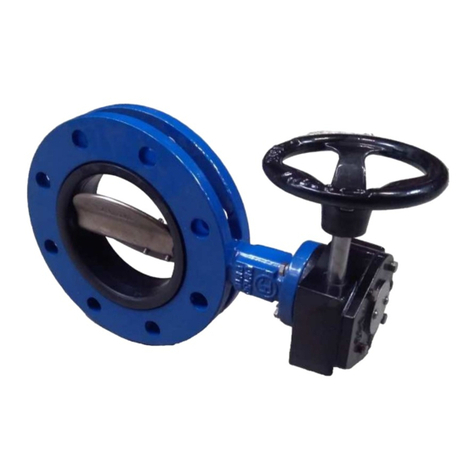
Jafar 2005 User manual

DOKUMENTACJA TECHNICZNO RUCHOWA 03-2016
Operation
and Maintenance Manual
KNIFE
GATE VALVES
Cat. no.
2005 2905
Approved for application by:
President of the JAFAR S.A. factory
The user's failure to follow the guidelines and regulations provided in the following
operating and maintenance manual releases the manufacturer from obligations and warranties.
Due to the continuous development of our company we reserve the right to introduce
modifications and design changes to the presented product.

DOKUMENTACJA TECHNICZNO RUCHOWA 03-2016
2
CONTENTS
1 TECHNICAL DESCRIPTION............................................................................................................................ 3
1.1 PRODUCT DESIGNATION AND IDENTIFICATION.............................................................................. 3
1.2 USE............................................................................................................................................................... 3
1.3 TECHNICAL CHARACTERISTICS........................................................................................................... 3
2 DESIGN............................................................................................................................................................... 3
2.1 DESCRIPTION OF THE VALVE DESIGN................................................................................................ 3
2.2 MATERIALS................................................................................................................................................ 4
2.3 DIMENSIONS.............................................................................................................................................. 5
2.4 STANDARDISATION................................................................................................................................. 7
2.5 ORDERING.................................................................................................................................................. 7
2.6 PRODUCTION AND ACCEPTANCE ........................................................................................................ 7
2.7 MARKING.................................................................................................................................................... 7
3 PROTECTION, STORAGE, TRANSPORT ....................................................................................................... 8
3.1 PROTECTIVE COATINGS......................................................................................................................... 8
3.2 PACKAGING............................................................................................................................................... 8
3.3 STORAGE.................................................................................................................................................... 8
3.4 TRANSPORT ............................................................................................................................................... 9
4 ASSEMBLY AND INSTALLATION................................................................................................................. 9
4.1 ASSEMBLY GUIDELINES......................................................................................................................... 9
4.2 INSTALLATION INSTRUCTIONS............................................................................................................ 9
4.3 OPERATION.............................................................................................................................................. 13
4.4 OH&S REGULATIONS............................................................................................................................. 13
5 WARRANTY TERMS AND CONDITIONS.................................................................................................... 13

DOKUMENTACJA TECHNICZNO RUCHOWA 03-2016
3
1 TECHNICAL DESCRIPTION
1.1 PRODUCT DESIGNATION AND IDENTIFICATION
The subject of this Operation and Maintenance Manual is:
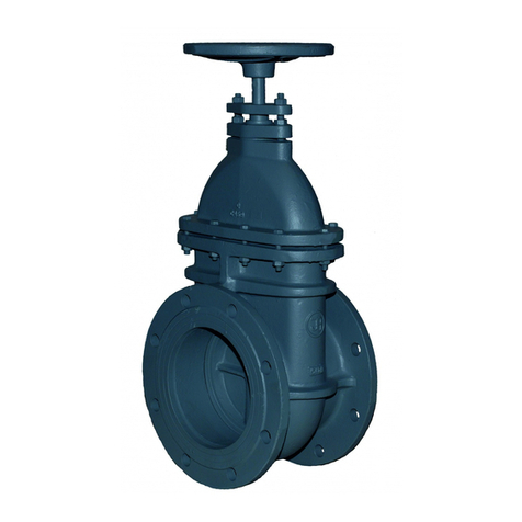
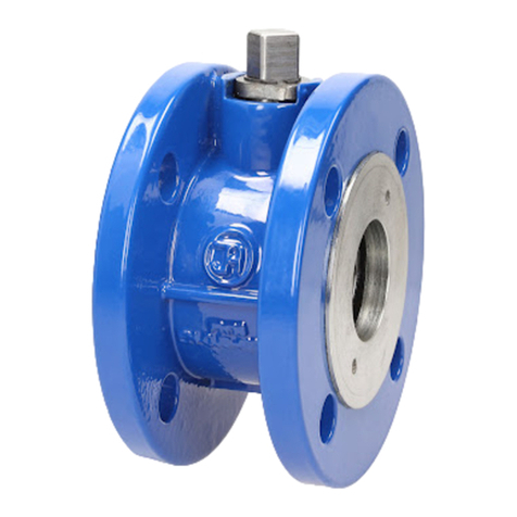
Type 2005, 2905 two-way flange-to-flange knife gate valve
- full bore design
- stainless steel knife (closer)
- available with rising or stationary spindle
- soft gland seal of the closer and the body
- drive gear guard.
1.2 USE
The Type 2005, 2905 two-way flange-to-flange knife gate valves are intended for water supply
systems, and especially sewage systems, and industrial processing systems. The valves can be operated both
in underground and overground installations as installed in vertical or horizontal pipelines.
CAUTION
Due to the limitations causes by application of specific materials in various operating
environment types, it is critical to precisely determine the operating conditions, i.e. the temperature,
pressure and medium characteristics. This will eliminate any problems during operation of the valve.
1.3 TECHNICAL CHARACTERISTICS
The flange-to-flange knife gate valves are intended for transfer of potable water, process water and
sewage, as well as other liquids as approved by the manufacturer.
- Operating temperature: to +70°C
- Nominal diameter (dimension) range: D50 to DN1000 [mm]
- Maximum medium flow rate: - liquid: max. 4 [m/s]
- gas: max. 30 [m/s]
- The driving torque at opening start and closing end is as listed below:
DN
[mm] 40 50 65 80 100 125 150 200 250 300 350 400 450 500 600 700 800 900 1000
Mmax
[Nm]
20 20 25 30 40 50 55 55 60 80 105 150 160 200 280 480 510 600 680
- Valve control mode: the standard version of knife gate has the clockwise closing sense of rotation.
The closing sense of rotation can be opposite on special order.
- The knife valves are designed for installation between flange end faces acc. to PN-EN 1092-2: 1999
with bolt holes for the pressure rating of PN10.
- Installation length: per the technical file, see for sizes.
- Nominal pressure PN values: - per size: DN40 to DN400 - 1.0 MPa
DN500 to DN600 - 0.6 MPa
DN700 to DN1000 - 0.25 MPa
2 DESIGN
2.1 DESCRIPTION OF THE VALVE DESIGN
The Type 2005, 2905 two-way flange-to-flange knife gate valves supplied by F.A. „JAFAR”S.A.
feature a full bore body, a stationary spindle (in the standard version) or a rising spindle, the closure seal
with a square section with a knife guide and placed in the body seat. The knife seal is reinforced by a
stainless steel bar which prevents washing the seal from the seat. The body seal of the knife is a multi-

DOKUMENTACJA TECHNICZNO RUCHOWA 03-2016
4
layered packing compressed by a gland with bolts. The gland on the delivered valve is loose and must be
tightened before installation. The knife gate valve body is a monolithic panel design. The gate knife clears
the body by turning the hand wheel (assisted with a driving gear from the size of DN500 to DN1000) which
drives the outer spindle held by a nut. The knife gate valves are two-way, permitting flow in both directions.
The top part of the body features tapped holes; the bottom part of the body features ports for connection
between flange ends. Table 4 shows the bolt sizing for flange ends (PN10 bolt hole layout).
2.2 MATERIALS
The table lists the structural materials of the flange-to-flange knife gate valves.
Item Part designation Material Reference standard
1Body Cast-iron, EN-GJS-400-15 PN-EN 1563: 2012
2Gland Cast-iron, EN-GJS-400-15 PN-EN 1563: 2012
3Knife Steel grade 1.4301 PN-EN 10088-1: 2014
4Stem Steel grade 1.0038 PN-89/H-84023.05
5 Spindle Steel grade 1.4021 PN-EN 10088-1:2014
6 Spindle nut Brass PN-EN 1982: 2010
7Gasket NBR PN-ISO 1629: 2005
8 Sliding bushings Polyamide
brass PN-EN 1874-1:2010
PN-EN 1982:2010
9 O-ring NBR PN-ISO 1629:2005
10 Handwheel Cast-iron, EN-GJL-250 PN-EN 1561: 2012
11 Seal PACK, asbestos-free sealant, NBR
rubber, asbestos-free sealant, scraper PN-ISO 1629:2005
Manufacturer's catalogue
12 Bolt Stainless steel, A2 PN-EN ISO 4014: 2011
13 Nut Stainless steel, A4 PN-EN ISO 4032: 2013
14 Washer Stainless steel, A2 PN-EN ISO 7091: 2003
15 Driving gear Manufacturer's catalogue

DOKUMENTACJA TECHNICZNO RUCHOWA 03-2016
5
2.3 DIMENSIONS
Stationary spindle (standard) Rising spindle (standard)
Knife gate size DN50-DN500 Knife gate size DN600-DN1000
wg. rys. szereg 20
[mm] [m
3
/h] [kg]
50 125 165 99 - - 286 206
14 8
65 145 185 118 - - 317 309 18 10
80 160 200 132 Ø19x6 - 335 494 22 11
100 180 220 156 Ø19x6 52 370 927 27 13
125 210 250 184 Ø19x6 420 1545 33 18
150 240 285 212 Ø23x6 494 2060 32 21
200 295 340 266 Ø23x6 - 575 4017 42 38
250 350 395 319 Ø23x8 - 680 5665 52 52
300 400 445 370 Ø23x8 - 794 8755 62 63
350 460 505 430 Ø23x10 M20x6 - 890 11640 72 83
400 515 565 480 Ø28x10 M24x6 86 - 990 15520 68 98
500 620 670 582 Ø28x12 M24x8 - 1820 22310 85 232
600 725 780 682 Ø31x12 M27x8 - 2050 33950 102 282
700 840 910 794 Ø31x14 M27x10 - 165 2480 48500 118 554
800 950 1015 901 Ø34x14 M30x10 - 190 2800 58200 116 680
900 1050 1115 1001 Ø34x16 M30x12 - 203 3070 77600 115 850
1000 1160 1230 1112 Ø37x16 M33x12 - 216 3430 97000 127 1150
Masa
10
16
d
48
76
200
250
320
56
DN H
M20x4
Ilość
obrotów do
otwarcia
PN M
x
n
10
M20x2
114 630
Kv
70
Dk
A
52
56
D l
x
n
815
M16x4
M16x2
[mm]
PS
[bar]
10
6
2,5
K

DOKUMENTACJA TECHNICZNO RUCHOWA 03-2016
6
Tabela nr2
wg. rys.
szereg 20
[mm]
[kg]
50 125 165 99 - - 551 SA 07.2 F7/F10 14 25
65 145 185 118 - - 582 18 29
80 160 200 132 Ø19x6 - 598 22 30
100 180 220 156 Ø19x6 52 632 27 32
125 210 250 184 Ø19x6 684 33 38
150 240 285 212 Ø23x6 740 32 41
200 295 340 266 Ø23x6 - 830 42 58
250 350 395 319 Ø23x8 - 930 52 72
300 400 445 370 Ø23x8 - 1100 62 86
350 460 505 430 Ø23x10 M20x6 - 1180 72 106
400 515 565 480 Ø28x10 M24x6 86 - 1286 68 146
500 620 670 582 Ø28x12 M24x8 - 1520 85 282
600 725 780 682 Ø31x12 M27x8 - 1725 102 332
700 840 895 794 Ø31x14 M27x10 165 2018 118 637
800 950 1015 901 Ø34x14 M30x10 190 2210 116 763
900 1050 1115 1001 Ø34x16 M30x12 203 2466 115 933
1000 1160 1230 1112 Ø37x16 M33x12 - 216 2608 127 1233
Ilość obrotów
do otwarcia
Masa
76
52
70
H
SA 07.6
SA 10.2
A
SA 16.2
F10
SA 14.2 F14
TYP napędu Kołnierz
przyłącza
M20x4
M16x4
M16x2
56
SA 14.6114
56
48
D
-
10
F16
[mm]
l
x
nDN
10
16
6
2,5
d M
x
nPN K
M20x2
PS
[bar]
10

DOKUMENTACJA TECHNICZNO RUCHOWA 03-2016
7
2.4 STANDARDISATION
PN-EN 1074-1:2002 Valves for water supply. Fitness for purpose requirements and appropriate
verification tests. General requirements.
PN-EN 1074-2:2002 Valves for water supply. Fitness for purpose requirements and appropriate
verification tests. Isolating valves.
PN-89/H-02650 Fixtures and pipelines Pressures and temperatures.
PN-EN 1092-2: 1999 Flanges and their joints. Circular flanges for pipes, valves, fittings and
accessories, PN designated. Cast iron flanges.
PN-EN19:2005 Industrial valves. Marking of metallic valves.
PN-EN 12266-1:2012 Industrial valves. Testing of valves. Pressure tests, test procedures and
acceptance criteria. Mandatory requirements.
PN-EN ISO 6708:1998 Definition and selection of DN (nominal size)
PN-EN 1559-1: 2011 Founding. Technical conditions of delivery. General.
PN-EN 1561:2012 Founding. Grey cast-iron.
PN-EN 1563:2012 Founding. Spheroidal graphite cast iron.
PN-EN 1370: 2012 Founding. Surface roughness inspection by visual tactile comparators.
PN-EN 10088-1:2014 Stainless steels. List of stainless steels.
PN-74/H-84032 Spring steel. Types of spring steels.
PN-EN 1982:2010 Copper and copper alloys. Ingots and castings.
PN-EN 12420:2002 Copper and copper alloys. Forgings.
PN-ISO 965-1: 2001 ISO general purpose metric screw threads. Tolerances. Principles and basic
data.
PN-ISO 2903:1996 ISO metric trapezoidal screw threads. Tolerances.
PN-EN ISO 4762:2006 Hexagon socket head cap screws.
PN-ISO 1629:2005 Rubber and latices. Nomenclature.
PN-EN ISO 12944-5:2009 Paints and varnishes. Corrosion protection of steel structures by protective
paint systems. Protective painting systems
2.5 ORDERING
Fixtures for transport of water belong to specific purpose industrial fixtures, therefore the order needs to
specify:
- catalogue number (equivalent of length),
- intended use e.g. water supply systems.
In addition specify:
- nominal diameter in acc. with PN-EN ISO 6708:1998,
- nominal pressure in acc. with PN-89/H–02650,
- body material in acc. with PN-EN 1563: 2012,
- max. operating temperature in acc. with PN-89/H – 02650.
2.6 PRODUCTION AND ACCEPTANCE
The Type 2005, 2905 two-way flange-to-flange knife gate valves are manufactured and subject to
acceptance as specified in PN-EN 1074-2:2002 (Valves for water supply. Fitness for purpose requirements
and appropriate verification tests. Isolating valves) and PN-EN 12266-1:2012 (Industrial valves. Testing of
valves).
All gate valves (100%) are subject to tightness tests. The external tightness of the body and the
tightness of closure are verified.
2.7 MARKING
The marking meets the requirements of the PN-EN-19:2005 and PN-EN-1074-1:2002.
The valve bodies feature markings on the front and back walls of the body chamber (or on the side walls
from DN300 to DN1000). The marking contains the following data:

DOKUMENTACJA TECHNICZNO RUCHOWA 03-2016
8
- valve type (defined by the product reference standard number)
- nominal diameter
- nominal pressure
- body material
- manufacturer's logo.
A rating plate with the following information is installed at a location specified in the technical
documentation:
-company name and logo,
- serial number of the product,
- temperature class of the seals,
- "B" construction marking and/or "CE" marking (if applicable),
- product type.
3 PROTECTION, STORAGE, TRANSPORT
3.1 PROTECTIVE COATINGS
All internal and external cast-iron surfaces are protected with epoxy paint applied using the
electrostatic method. The paint has a certificate allowing for its use in contact with food products.
The thickness of the corrosion-protection layer is at least 250 µm.
The casting surfaces are prepared for the application of the epoxy layer in accordance with the technical
documentation and the PN-EN ISO 12944-5:2009 standard.
The bolts connecting the body with the cover are stainless steel (A2).).
3.2 PACKAGING
The gate valves are packaged on EURO palettes (1200x800) and protected using a heat-shrink cover.
3.3 STORAGE
The gate valves shall be stored under a roof.

DOKUMENTACJA TECHNICZNO RUCHOWA 03-2016
9
3.4 TRANSPORT
Transport the knife gate valves on sheltered vehicles.
The manufacturer recommends slings for transport and installation of valve sizes from DN125 to DN1000.
4 ASSEMBLY AND INSTALLATION
4.1 ASSEMBLY GUIDELINES
The Type 2005, 2905 flange-to-flange knife gate valves can be installed in underground or overground
pipelines both in horizontal or vertical orientation. The knife gate valves are designed for mounting between
flange ends of the pipelines sized for the PN10 bolt hole layout acc. to PN-EN 1092-2: 1999. The gland on
the delivered valve is loose and must be tightened before installation.
4.2 INSTALLATION INSTRUCTIONS
When installing fixtures consult the technical and commercial documentation, check the pipeline
operating conditions and media against the data declared by the manufactured. Every change in operating
conditions requires consultation with the fixture manufacturer.
Before commencing assembly remove the plugs from the main opening and inspect the conditions of
internal surfaces and clean them th
oroughly with water if required

DOKUMENTACJA TECHNICZNO RUCHOWA 03-2016
10
CAUTION!
If the knife gate valve is installed at a system termination, use counterflanges at the connection.
Bolt
thread
size
Bolt tightening torque
Bolt strength class
6.9 8.8 10.9
[Nm]
M4 2.7 3 4.3
M5 5 6 8,5
M6 9 11 15
M8 20 25 35
M10 42 51 70
M12 73 87 120
M14 115 135 195
M16 180 210 300
M18 245 290 410
M20 350 410 580
M22 470 560 780
M24 560 710 1000
M27 900 1050 1480
M30 1200
1430 2010
M33 1630
1940 2700
M36 2100
2490 3500
M39 2720
3220 4550
Table of maximum tightening torques for individual bolts for tightening the knife gate valve gland.
Note that the system must not expose the valve to bending or tensile stress from loading with the
unsupported pipeline sections. Assemble with consideration to pressure and temperature compensation of the
pipeline. The valve assembled and adjusted by the manufacturer is ready for installation. Any dismantling of
the valve components may result in loss of seal.
The connection of the gate valve and the diagram of possible installation directions are presented in the
figure below:

DOKUMENTACJA TECHNICZNO RUCHOWA 03-2016
11
1. - Knife gate; 2. - Pipeline flange end; 3. - Assembly bolt; 4. - Seal; 5. - Nut; 6. - Washer

DOKUMENTACJA TECHNICZNO RUCHOWA 03-2016
12
Use of bolts for the knife gate valve Type 2005, 2905.
DN [mm] 50 65 80 100 125 150 200 250 300
D [mm] 165 185 200 220 250 285 340 395 445
K [mm] 125 145 160 180 210 240 295 350 400
lxn 4x18
4x18
6x18
6x18
6x18
6x22
10x22
8x22
8x22
Thread-
in bolts
(l x M x
length)
4
M16
x25
4
M16
x25
4
M16
x30
4
M16
x30
4
M16
x40
4
M20
x40
4
M20x
40
8
M20
x40
8
M20
x40
Z [mm] 11 11 12 12 12 13 13 13 15
Bolts
with nuts
(l x M x
length)
4
M16
x90
4
M16
x90
6
M16
x110
6
M16
x110
6
M16
x120
6
M20
x130
10
M20x
140
8
M20
x150
8
M20
x150

DOKUMENTACJA TECHNICZNO RUCHOWA 03-2016
13
DN [mm] 350 400 500 600 700 800 900 1000
D [mm] 505 565 670 780 895 1015
1115
1230
K [mm] 430 515 620 725 840 950 1050
1160
lxn
10x22
10x26
12x26
12x30
14x30
14x30
16x30
16x33
Thread-
in bolts
(l x M x
length)
6
M20
x55
6
M24
x55
16
M24
x55
16
M27
x55
20
M27
x60
20
M27
x60
24
M30
x60
24
M33x
80
Z [mm] 15 20 20 25 40 40 50 55
Bolts
with nuts
(l x M x
length)
10
M20
x150
10
M24
x200
12
M24
x200
12
M27
x250
14
M27
x280
14
M27
x280
16
M30
x300
16
M33x
350
4.3 OPERATION
The knife gate valve shall be operated according to all relevant requirements for cut-off valves, i.e.
either in fully open or fully closed positions. Leaving the knife gate valve partially opened (or closed) may
result in seal failure. To ensure full performance, switch the knife gate valve periodically (once a year, from
fully open to fully closed).
MAINTENANCE
Lubricate the spindle in the nut with a grease, e.g. Ł15 or equivalent (replenish the lubricant at least
once a year) by applying the lubricant with a brush and then fully turning the valve open and closed.
Lubricate the knife for a better slip with a dry Teflon grease in spray, e.g. Pulsar or Kontaflon 85.
(Relubricate every 20 full cycles more frequently in harsh operating conditions.) Coat the knife when the
gate valve is fully open.
Exceeding the operating limits of the valve may result in damage that will not covered by the
suretyship granted by the manufacturer.
4.4 OH&S REGULATIONS
Guidelines and recommendations provided in OH&S regulations applicable to pipelines and devices
installed in water stations, thermal power plants, water purification plants, sewage processing plants, pump
stations and other similar structures as well as the regulation on the general occupational health and safety
regulations (use of upper limb protection, use of lower limb protection, head protection, protective
clothing) in cases of exposition to low and high temperatures apply when using gate valves with soft seal.
The use of products otherwise than in accordance to their intended use is not allowed.
5 WARRANTY TERMS AND CONDITIONS
The product assembled, installed and operated in compliance with this Manual is covered by a
commercial warranty from the manufacturer.
The warranty terms, conditions and period are specified in the relevant Warranty Sheet.
This manual suits for next models
1
Table of contents
Other Jafar Control Unit manuals
Popular Control Unit manuals by other brands

Watermark
Watermark Reefe rainpro RM1500-2 Installation and operating instructions

Pfeiffer
Pfeiffer TC 110 operating instructions

Lacava
Lacava 0648 owner's manual

Lutron Electronics
Lutron Electronics Maestro Wireless MRF2-3PD-1 manual

Unitronics
Unitronics Land Vision280 user guide

Eaton
Eaton Series NRX installation instructions

Wolf
Wolf FWS-2-60 installation instructions

Georg Fischer Piping Systems
Georg Fischer Piping Systems CONTAIN-IT Plus instruction manual

Aaeon
Aaeon PER-C20L manual

TEGO
TEGO Roundline Master quick start guide

Unitronics
Unitronics IO-AI4-AO2 installation guide

DLP Design
DLP Design USB-Parallel FIFO Module DLP-USB245R user guide