jakob HIT-TRAC 8B User manual

jakob.com ∙ [email protected]om ∙ Copyright by Jakob AG Switzerland 1 / 21
User Guide
Version 06 / 15.05.2023
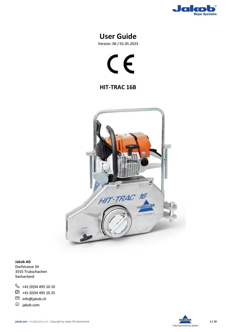
HIT-TRAC 8B
HIT-TRAC 8A
HIT-TRAC 8B HIT-TRAC 8A
Jakob AG
Dorfstrasse 34
3555 Trubschachen
Switzerland
+41 (0)34 495 10 10
+41 (0)34 495 10 25
jakob.com

jakob.com ∙ [email protected]om ∙ Copyright by Jakob AG Switzerland 2 / 21
Prüfzertifikat
Wir bestätigen, dass die genannte Maschine geprüft wurde und den Auftragsanforderungen, Spezifikationen, Zeichnungen
sowie gültigen Normen und Vorschriften entspricht.
Motorseilzugmaschine HIT-TRAC 8B mit Benzinmotor
Motorseilzugmaschine HIT-TRAC 8A mit Akkumotor
Certificat d'inspection
Nous déclarons que le produit faisant l'objet du certificat a été contrôlé et est conforme aux exigences de la commande, aux
spécifications, aux dessins ainsi qu'aux normes et prescriptions.
Machine motorisée de traction par câble HIT-TRAC 8B avec moteur à essence
Machine motorisée de traction par câble HIT-TRAC 8A avec moteur à batterie
Test certificate
We hereby confirm that the machine described below was tested and satisfies the requirements posed in the order, specifi-
cations, drawings as well as the relevant valid standards and regulations.
Motor-driven rope pulling machine HIT-TRAC 8B with petrol motor
Motor-driven rope pulling machine HIT-TRAC 8A with battery motor
Certificato di prova
Confermiamo che la macchina menzionata è stata controllata e che è conforme, sotto ogni aspetto, ai requisiti di incarico,
alle specifiche, ai disegni nonché alle norme e alle disposizioni.
Macchina motorizzata con comando a cavo flessibile HIT-TRAC 8B con motore a benzina
Macchina motorizzata con comando a cavo flessibile HIT-TRAC 8A con motore a batteria
Geräte Nr. /N° de la machine / Machine no.:
................................................
HSS ID
................................................
Art. Nr./ N° art./ Art. no.:
................................................
Motor-Nr. / N° du moteur / Motor no.:
................................................
Datum/Date/Date:
................................................
Unterschrift/Visa/Visa:
................................................

jakob.com ∙ [email protected]om ∙ Copyright by Jakob AG Switzerland 3 / 21
Content
1General description................................................................................................................................................................6
1.1 Components ................................................................................................................................................................. 6
1.2 Components HIT-TRAC 8B ............................................................................................................................................7
1.1 Components HIT-TRAC 8A............................................................................................................................................7
2General safety rules ............................................................................................................................................................... 8
2.1 Safety information in this operation manual ............................................................................................................... 8
2.2 Intended use.................................................................................................................................................................8
2.3 Authorized operators ...................................................................................................................................................9
2.4 Warranty and liability provisions..................................................................................................................................9
2.5 Behavior in an emergency situation.............................................................................................................................9
2.6 Product specific hazards...............................................................................................................................................9
2.6.1 Hot surfaces .............................................................................................................................................................9
2.7 Preparation................................................................................................................................................................. 10
2.7.1 Location.................................................................................................................................................................. 10
2.7.2 Anchoring...............................................................................................................................................................10
2.7.3 Load........................................................................................................................................................................ 10
2.7.4 Traction rope.......................................................................................................................................................... 11
2.7.5 Inserting rope......................................................................................................................................................... 11
2.8 Working ...................................................................................................................................................................... 11
2.8.1 Pulling and lifting.................................................................................................................................................... 11
2.8.2 Restart under load HIT-TRAC 8B ............................................................................................................................ 12
2.8.3 Lowering.................................................................................................................................................................12
2.9 Decommissioning .......................................................................................................................................................12
2.10 Storage and transport ................................................................................................................................................12
3Design and function .............................................................................................................................................................13
3.1 Technical specifications..............................................................................................................................................13
3.2 Operation HIT-TRAC 8B ..............................................................................................................................................14
3.3 Operation HIT-TRAC 8A ..............................................................................................................................................14
3.4 Braking........................................................................................................................................................................14
4Operation.............................................................................................................................................................................15
4.1 Preparation................................................................................................................................................................. 15
4.1.1 Petrol motor...........................................................................................................................................................15
4.1.2 Battery Motor ........................................................................................................................................................ 15
4.1.3 Location.................................................................................................................................................................. 15
4.1.4 Anchoring...............................................................................................................................................................15
4.1.5 Load........................................................................................................................................................................ 16
4.1.6 Traction rope.......................................................................................................................................................... 17
4.1.7 Inserting rope......................................................................................................................................................... 17
4.2 Working ...................................................................................................................................................................... 18
4.2.1 Pulling and lifting.................................................................................................................................................... 18
4.2.2 Restart under load ................................................................................................................................................. 18

jakob.com ∙ [email protected]om ∙ Copyright by Jakob AG Switzerland 4 / 21
4.2.3 Lowering.................................................................................................................................................................18
4.3 Decommissioning .......................................................................................................................................................19
4.3.1 Taking rope out of the machine.............................................................................................................................19
4.3.2 Dismantling machine..............................................................................................................................................19
4.4 Storage and transport ................................................................................................................................................19
5Faults.................................................................................................................................................................................... 20
6Maintenance........................................................................................................................................................................21
7Spare parts ........................................................................................................................................................................... 21
8Disposal................................................................................................................................................................................ 21
Preface
You made a good choice when you selected the Jakob AG HIT-TRAC motor-driven rope pulling machine. This state of the art
rope pulling machine allows you to pull, lift and lower loads. Operation and maintenance are very simple and with correct
handling ensure trouble-free and reliable operation.
It may be that you already know how your recently purchased rope pulling machine functions.
Nevertheless, read the following safety instructions safely before first commissioning.
Important information in the operation manual help you:
-To avoid hazards,
-to keep repair costs and downtimes to a minimum and
-to increase the reliability and service life of your rope pulling machine.
Always keep this operation manual at the place where the motor-driven rope pulling machine is used, and make sure that
anyone who uses the machine reads and applies the information in the manual. It must be available for all operation person-
nel, to avoid errors during handling.
As well as the operation manual and the locally applicable accident prevention regulations, the recognized specialist rules for
safe and proper working must be complied with.
We wish you every success and enjoyment using your product from Jakob AG.

jakob.com ∙ [email protected]om ∙ Copyright by Jakob AG Switzerland 5 / 21
EG-Konformitätserklärung
Déclaration de conformité CE
EC declaration of conformity
Wir / Nous / We
Jakob AG
Dorfstrasse 34
CH-3555 Trubschachen
erklären hiermit, dass die Maschine
déclarons par la présente que la machine
hereby declare that the device
HIT-TRAC 8B
HIT-TRAC 8A
in seiner Konzipierung und Bauart sowie in den von uns in Verkehr gebrachten Ausführungen den grundlegenden Sicherheits- und Gesundheitsanforderun-
gen der EG-Richtlinie Maschinen entsprechen.
Bei nicht bestimmungsgemässer Verwendung, sowie bei nicht von uns freigegebenen Umbauten oder Änderungen, verliert diese Erklärung ihre Gültigkeit.
Zudem verliert diese Konformitätserklärung ihre Gültigkeit, wenn die Bestimmungen der Betriebs- und Instandhaltungsanleitung nicht befolgt oder missach-
tet werden.
satisfait aux exigences fondamentales de la directive machines CE en matière de sécurité et de santé, tant du point de vue de sa conception et de sa construc-
tion que pour toutes les versions que nous avons mises sur le marché. En cas d’utilisation non conforme ou de modification ou transformation non approu-
vées par nous, cette déclaration perd sa validité. Cette déclaration perd également sa validité en cas de non-respect des instructions d’utilisation et de main-
tenance.
conforms to the health and safety requirements of the EC Machinery Directives in its conception and design, as well as in the
version placed on the market by us. In the event of improper use, as well as modifications or changes which are unauthorised
by us, this statement loses its validity. This declaration of conformity also loses its validity if the relevant user guide and
maintenance manual are not followed or are violated.
Zutreffende EG-Richtlinie: EC Machinery Directive 2006/42/EC
Directive CE concernée:
Applicable EC directives:
Angewandte harmonisierte Normen: DIN EN 14492-1: 2010-06
Normes harmonisées appliquées: EN ISO 12100: 2011-01
Applied harmonised standards:
Stv. Leiter Technik Leiter Seil- & Hebetechnik
Suppléant du chef technique / deputy Head of Technology Chef câbles et levage / Head of Hoisting and Lifting
Thomas Gerber Urs Schneider

jakob.com ∙ [email protected]om ∙ Copyright by Jakob AG Switzerland 6 / 21
1General description
The HIT-TRAC motor-driven rope pulling machine is designed to pull, lift and lower loads.
The traction element used is a special HABEGGER HIT-TRAC rope of any length, which is steered around the drive wheel via a
series of guide elements, and then exits once more in the unloaded condition.
1.1 Components
1 Pressure roller 10 Information sign
2 loose rope end 11 Housing cover
3 Traction rope 12 Cover closure
4 Rope guide 14 HSS NFC Chip
6 Guide roller 25 Brake release lever
8 Anchor hook 26 Rope loosening crank
9 Drive wheel

jakob.com ∙ [email protected]om ∙ Copyright by Jakob AG Switzerland 7 / 21
1.2 Components HIT-TRAC 8B
30 Petrol motor 31 Starter motor
32 Throttle lever 33 Throttle lock
38 Chain brake
1.1 Components HIT-TRAC 8A
35 Battery motor 36 Battery
37 Trigger 38 Lockout Button
38 Chain brake

jakob.com ∙ [email protected]om ∙ Copyright by Jakob AG Switzerland 8 / 21
2General safety rules
The HABEGGER motor-driven rope pulling machine HIT-TRAC confirms to the current state of the art. To
protect against accidents, it is equipped with effective safety devices according to the recognized tech-
nical safety standards, guidelines and laws.
However: Laws, regulations and safety devices do not offer protection against carelessness and negli-
gence!
Only use the motor-driven rope pulling machine in perfect condition, complying with the operation man-
ual.
Before you work with the motor-driven rope pulling machine, you must carefully read and comply with
the safety information below.
This is for your safety!
2.1 Safety information in this operation manual
For hazards, notes and important information, the following symbols and descriptions are used:
-Notices are particularly important information which you must comply with when operating the equip-
ment for its intended use.
-Caution! Note indicates hazard for the machine, machine parts and the environment.
-Danger! Note referring to hazards to health and the life of the operator and other persons in the working
area of the motor-driven rope pulling machine.
-
-Warning of hot surfaces.
-Wear ear defenders
2.2 Intended use
The HIT-TRAC motor-driven rope pulling machine is designed to pull, lift and lower loads.
-The HIT-TRAC must not be used to transport persons.

jakob.com ∙ [email protected]om ∙ Copyright by Jakob AG Switzerland 9 / 21
2.3 Authorized operators
The motor-driven rope pulling machine must only be used by a specialist person who is authorized. As the operating com-
pany for the motor-driven rope pulling machine, make sure that the operation manual is made accessible to the operator and
ensure that they have read and understood it.
2.4 Warranty and liability provisions
The liability and warranty provisions of the general T&C of Jakob Rope Systems apply. Especially T&C points 10 and 11.
2.5 Behavior in an emergency situation
Before starting work, always inform yourself whether and where there is a mobile phone network or where a traditional tele-
phone is available. Check the availability of a first-aid box.
2.6 Product specific hazards
2.6.1 Hot surfaces
During operation the components of the device warm up to differing degrees.
-CAUTION! Skin burns!
-If touched, hot surfaces can cause skin burns.
-After shutting down operation, wait until the components in the working area have cooled down suffi-
ciently so that their surfaces can be touched safely. Some surfaces can be hotter than others!
-If required wear protective gloves/protective clothing.

jakob.com ∙ [email protected]om ∙ Copyright by Jakob AG Switzerland 10 / 21
2.7 Preparation
2.7.1 Location
-Personnel must not be located on a structure hanging on the HIT-TRAC.
-When working always make sure you have a firm and safe location to stand in.
-Always stand outside the hazard area of the load to be moved, and never in the way of the exiting rope.
-You need sufficient room to move. Therefore make sure you have a sufficiently large area to stand in.
-Do not use ladders as a standing area.
-If your location is unsuitable: Install deflection roller and select a better location.
-When installing the machine take care that no external hazards can act on the rope pulling machine, the
traction rope, the load and the operator personnel. (e.g. falling objects, passing vehicles, electrical over-
head lines, and so on)
-During operation, ensure that the machine is not standing directly in water (or snow).
-
Following contact with water, you should have your HIT-TRAC checked by Jakob AG so that the brakes can be dried and
greased. If the brakes are wet, the load can either not be lowered or can only be lowered jerkily.
2.7.2 Anchoring
-Attach the machine with sufficiently strong strops or slings to the anchor bolts.
-Do not use damaged strops or lifting slings.
-In the unloaded condition, rope couplings and fixings must not come undone of their own accord.
-The machine must be able to adjust freely in the pulling direction of the rope. Otherwise there is a risk of
the housing breaking!
-When remaining in the same location for longer periods: Regularly check attachments!
2.7.3 Load
-The pulling force must not be greater than the rated pulling force of the machine.
-Secure free hanging loads against turning!
-The inherent stability of the load must be guaranteed, to prevent sliding off or tipping during the work.
-Pay attention to obstacles, which could cause the load to tip or become stuck.
-Uncontrolled loading (e.g. buckets, containers) during the lift or at interim positions is prohibited.
-When tensioning and anchoring, take into account possible stress spikes (in static condition) due to exter-
nal influences.
-Excessive impacts and loading on the pulling machine (e.g. anchoring of moving machinery, wind and so
on) must be prevented by the use of a strain relief rope.
-The efficiency of deflection devices must be considered when designing the system.

jakob.com ∙ [email protected]om ∙ Copyright by Jakob AG Switzerland 11 / 21
2.7.4 Traction rope
The condition of the rope is decisive for the reliability of the drive system.
Rope structure and inherent strength (transverse compressive strength, impact resistance) must resist the loads which occur.
-Only suitable original HABEGGER ropes must be used.
-The pulling rope must not be lubricated, and must be kept clean.
-The rope diameter must match that on the type plate.
-Damage of the rope: crushed, unwound, non-circular, kinked ropes or ropes with strand breaks or tangles
must not be used. (ISO 4309)
-Ropes with broken wires: remove carefully and correctly.
-Rope connections, sleeves, compression heads, short splices and so on must not run through the drive
system.
-When deflecting the rope over sharp edges, obstacles and so on protect the rope using suitable floor roll-
ers or supports made of wood or plastic.
-Due to unloading of the rocker, the loose robe end (2) must not hang freely for more than 50 m.
-For lengths greater than 20 m the loose rope end (2) must be rolled up properly (rollers, reels). Rope
twists, tangles, kinks etc. must be avoided!
2.7.5 Inserting rope
-Before all work, close and lock housing cover (11) above the drive system.
-When handling wire ropes wear gloves.
2.8 Working
2.8.1 Pulling and lifting
-In an emergency Release throttle lever (32/37). The driving wheel will immediately stop moving and the
built-in backstop will stop the driving wheel from turning backwards.
-The loose rope end (2) must be able to exit the pulling machine unhindered.
-Never pull hooks against the housing.
-In situations where the work cannot easily be seen: Observations by assistants, if necessary with radio
contact.
-Before starting work, check the correct direction of rotation for lifting and lowering.
-Observe the rope during the movement.
-Observe the movement of the load.
-Risk of slipping with low load!
-When pulling make sure that neither the housing nor the rope are deflected or tilted by objects or obsta-
cles.
-When pulling diagonally upwards the rope pulling machine can tilt. Place wood underneath, or avoid diag-
onal pull with rope roller.
-If the brake release lever (25) is not swivelled upwards, the load will fall at lowering speed after the throt-
tle lever (32/37) is released.
Pivot brake release lever (25) upwards immediately
-Wear ear defenders when working with the machine!

jakob.com ∙ [email protected]om ∙ Copyright by Jakob AG Switzerland 12 / 21
-During operation, the pressure roller (1), in connection with the rope geometry, can lead to elongation
slippage and accumulation of the rope so that it briefly lifts out of the V-groove of the drive sheave. The
subsequent compensation of this rope protrusion usually results in a regular, characteristic cracking or
banging noise. This phenomenon is therefore operational. The machine operation can be continued with-
out hesitation.
2.8.2 Restart under load HIT-TRAC 8B
-Allowing the coupling to slide through for too long leads to overheating and early wear and tear.
2.8.3 Lowering
-In an emergency Release throttle lever (32/37). The driving wheel will immediately stop moving and the
built-in backstop will stop the driving wheel from turning backwards.
-Risk of falling! Pay attention to loose rope end (2)! Stop lowering movement 2 m before the end of the
rope end at the latest.
-The loose rope end (2) must be able to run freely and without deformations and tangles into the machine.
2.9 Decommissioning
-The pulling rope (3) must be unloaded during decommissioning.
-Loads must be secured.
2.10 Storage and transport
-The device must be transported on pallets, secured against sliding and tilting.

jakob.com ∙ [email protected]om ∙ Copyright by Jakob AG Switzerland 13 / 21
3Design and function
3.1 Technical specifications
HIT-TRAC
8B
8A
Rated force (pulling, lifting, lowering)
8 kN
Overload protection at
ca. 10 kN
Rope speed lifting
ca. 10 m/min
ca. 8 m/min
Rope speed lowering at 800 kg
ca. 10 m/min
ca. 8 m/min
Switch-on period lifting at rated force
100%
Switch-on period lowering at rated
force
Limited by brake temperature
For rated force approx. 30 m without cooling
Operating time / tankful
tankful
approx. 15 min (150 m rope movement)
Battery charge AP 300S
approx. 9 min (70 m rope movement)
Rope movement: lifting/lowering
unlimited/unlimited
Dimensions
Length
Width
Height
541 mm
260 mm
530 mm
541 mm
260 mm
505 mm
Effective diameter of drive wheel:
160 mm
Rope pulling machine own weight
30 kg
28.5 kg
Gear grease
Liquid grease Microlube GB 0
Pulling rope type
Diameter
Construction
Length
Breaking strain
HABEGGER HIT-TRAC rope
8.2 mm
4 x 25 FW+FC galvanized
any
50 kN
Drive group (DIN 15 020)
1 Cm
Sound power level LWA
max. 114 dB
max. 100 dB
Permissible temperature range for use
and storage
-20°C to +40°C
-10°C to +40°C
Driving motor:
Model
Emission standards MS260
Emission standards MS261
Output
Fuel
Fuel capacity
2 stroke Petrol motor
STIHL MS260 / STIHL MS261
Rl 97/68/EG (EU I)
VER (EU) 2016/1628 (EU V)
2,6 kW
2 stroke petrol
oil mixture according to Stihl’s require-
ments
0.50 l
Battery motor
STIHL MSA 220 C
-
-
1.8 kW
-
-
Battery
Weight
Energy content
Battery cell technology
End of charge voltage
Charging time 80%
Charging time 100%
-
AP 300 S
1.8 kg
281 Wh
LITHIUM-ION
42 V
30 min
45 min
Quick charger
Rated voltage
Charging current
Weight
-
AL 500
220-240 V
12 A
1.3 kg

jakob.com ∙ [email protected]om ∙ Copyright by Jakob AG Switzerland 14 / 21
3.2 Operation HIT-TRAC 8B
The machine is operated by a petrol engine using a friction clutch. If the machine is overloaded, the coupling slips through
and the load cannot be hoisted or pulled.
3.3 Operation HIT-TRAC 8A
The machine is operated by a battery motor. If the machine is overloaded, the motor stops and the load cannot be hoisted or
pulled.
3.4 Braking
The motor does not allow braking. The load is stopped using a brake which is built into the machine which needs to be re-
leased by hand for lowering.

jakob.com ∙ [email protected]om ∙ Copyright by Jakob AG Switzerland 15 / 21
4Operation
4.1 Preparation
4.1.1 Petrol motor
The STIHL petrol motor should be operated according to the STIHL operating instructions.
-Do not fill with chain lubricant
-Use the blend of fuel recommended in the STIHL operating instructions.
-Shake the fuel mixture thoroughly before refuelling. The fuel should not be older than 2 years old.
When working at high altitudes or in unfavourable climate conditions:
-Optimise carburettor settings or Reduce load accordingly.
-If being used regularly in mountainous areas, a special carburettor can partially compensate for the reduc-
tion in power.
4.1.2 Battery Motor
The STIHL Battery Motor should be operated according to the STIHL operating instructions.
-With full battery capacity must not be lowered! It has to be raised briefly before.
-Do not fill with chain lubricant.
4.1.3 Location
Suitable location for the rope puller.
4.1.4 Anchoring
The rope puller is anchored using the anchor bolt (8) with a suitable attachment on the attachment point.
The best anchor points are:
-Solid objects and constructions
-Concreted rings
-Eyelets or rods
Natural anchoring points:
-Heavy/strong boulders
-Trees
-Other suitable objects
Technical anchor points:
-Habegger field anchor with posts
-Rock anchor, concrete anchor
-Round wood anchor in ground
-These anchors depend very much on the ground conditions.

jakob.com ∙ [email protected]om ∙ Copyright by Jakob AG Switzerland 16 / 21
4.1.5 Load
The load must be determined before pulling. A suitable load dynamometer can be used for this.
Suitable means of attachment are used to fix the load on the pulling hook. These prevent the load slipping or tilting during
work. Suitable attachment equipment includes for example eyes, slings, strops, straps.
For larger rated loads:
Reduce the pulling force by using pulleys.
-The efficiency of the rope block must be included in the design of the rope system. As a rule, an efficiency
of 98% per deflection can be expected.
-Icy pulleys or stiff bearings can lead to an extreme deterioration of efficiency in the pulley block. The pul-
leys must be checked for smooth running before pulling in the rope.
-The choice of reeving can have an influence on the alignment of the rope blocks under tensile force. If
they are misaligned during operation, this can lead to an extreme deterioration of the efficiency. The
reeving must be changed in this case. The original operating instructions for the rope blocks must be con-
sidered.
Calculation example:
Load Transmission
Number of rollers
Efficiency (guideline value)
Traction force at 8 kN
1x
0
100%
8 kN
2x
1
98%
15.68 kN
3x
2
96% (0.98 x 0.98)
23.04 kN
4x
3
94% (0.98 x 0.98 x 0.98)
30.08 kN
5x
4
92% (0.98 x 0.98 x 0.98 x
0.98)
36.8 kN
…
…
…
…
8x
7
87 % (0,98 ^ 7)
55.68 kN
…
…
…
…
20x
19
68 % (0,98 ^ 19)
108.8 kN
Lifting/lowering
Pulling

jakob.com ∙ [email protected]om ∙ Copyright by Jakob AG Switzerland 17 / 21
4.1.6 Traction rope
Unwinding and winding up the rope must be done properly according to ISO 4309.
Matching accessories:
-HABEGGER rope reel and carrying tube
-Reel drive 4 (Art.: 00395)
-Reel drive 6 (Art. 01651)
4.1.7 Inserting rope
Only insert the rope at the end of the preparation work. This allows the rope to be pre-tensioned by hand and laid around
the drive wheel at a suitable point without an idle stroke. The rope is laid into the drive wheel according to the following
sketch or information sign (10).
1. Unlock housing cover (11) with cover handle (12) and fold up.
2. Create a loop of rope, pulling rope (3) at the bottom.
3. Swivel in pulling rope (3) at the bottom in the cable guide (4).
4. Lay loose rope end (2) at the top in the cable guide (4) and under pressure roller (1) (lift rocker).
5. Lay rope loop in rope groove of drive wheel (9).
6. Pulling rope (3) over guide roller (6) (press rocker downwards).
7. On loose rope and (2) pull the rope into the rope groove of the drive wheel (9).
8. Check correct location of rope one more time.
9. Close housing cover (11) and lock with cover handle (12).

jakob.com ∙ [email protected]om ∙ Copyright by Jakob AG Switzerland 18 / 21
4.2 Working
4.2.1 Pulling and lifting
1. Start the motor (30/35)
2. Check that the chain brake (38) is disengaged. (see arrow) To protect the
coupling, the chain brake should not be engaged for too long.
3. Set the driving wheel into motion using the throttle lever (32/37). Open the
thrttle enough that the motor runs smoothly and the centrifugal clutch grips
properly.
4. Release throttle lever. The driving wheel will immediately stop moving and
the built-in brake will stop the driving wheel from turning backwards.
4.2.2 Restart under load
1. Release chain brake (38)
2. Quickly pull the throttle lever (32/37) so that the motor can reach the required speed and the centrifugal clutch
can instantly deliver the required torque.
4.2.3 Lowering
1. Power off motor.
2. To lower the load or relieve tension in the rope, release the brake by pulling the brake release lever (25) on the
back of the machine. The chain brake (38) needs to be released for this.
3. For large enough loads (larger than approx. 100 kg), the load will move of its own accord when the brake re-
lease lever is pulled away from the housing. In this case, the centrifugal brake limits the load’s lowering speed.
The load stands still as soon as the brake lever is released.
4. If the brake release lever (25) is pivoted right down, it locks and the brake stays open!
5. For smaller loads and to release tension in the rope, i.e. when the load does not move of its own accord when
the brake is released, the crank (26) at the front of the housing must be switched to the other side, when the
brake is released, and pressed against the housing until the claw coupling clicks into place, possibly after being
rotated. By turning the crank (26) in an anticlockwise direction the load will be lowered or, respectively, the
rope tension will be relieved.
The rope speed is dependent on the speed of the hand crank.
6. After the rope tension has been relieved, pivot the brake release lever upwards again to engage the brake.
As energy produced during lowering is converted into frictional heat, the distance the load can be lowered by is restricted to
protect the lowering brake against overheating. The table provides the maximum values:
Lowering force
Lowering distance
8 kN
20 m
6 kN
25 m
4 kN
40 m
2 kN
80 m
If the load is to be lowered over longer distances, the brake should be allowed to cool (air) and then lowered the rest of the
distance.

jakob.com ∙ [email protected]om ∙ Copyright by Jakob AG Switzerland 19 / 21
4.3 Decommissioning
4.3.1 Taking rope out of the machine
1. Pulling rope (3) must be loose
2. Unlock housing cover (11) with cover handle (12) and fold up.
3. Remove loose rope and (2) at the top in the cable guide (4) and under pressure roller (1)
4. Remove pulling rope (3) at the bottom in the cable guide (4)
5. Remove complete rope from the machine and wind up properly
6. Close housing cover (11) and lock with cover handle (12).
4.3.2 Dismantling machine
-Release machine from the anchor point
4.4 Storage and transport
The device must be stored in a dry place. During transport and storage, the device must be covered against dust.

Faults
Possible cause
Measures
Petrol motor cannot be started
Too little petrol
Single lever operation on motor set to
stop
other causes
Refuel
Switch lever to start
see STIHL operating instructions.
Petrol motor “dies” when starting
up
Altitude too great over approx. 2200
m above sea level
Poor carburettor settings
Load is greater than permitted tensile
force
Adjust carburettor
see STIHL operating instructions.
Reduce load or employ pulley block
Battery motor turns off
Battery empty
Load greater than permissible tensile
force
Engine too cold
Engine too warm
Charge the battery
Reduce the load
Allow unit to warm up at idle speed
Engage chain brake, remove battery,
and allow motor to cool down.
Rope does not move, even though
drive wheel turns
Rope incorrectly inserted
Too small or too thin
rope installed
Severe wear on rope
Drive wheel or rope excessively
greased
Rope groove in drive wheel strongly
contaminated
No load on rope
Install rope according to sketch
Install correct rope
Install new rope
Clean
Clean
Load rope
The driving system is not moving
despite the throttle on the running
motor being open
Chain brake (38) released (blocked)
Broken V-belt
Centrifugal clutch on Petrol motor
worn out
Sliding clutch 8B worn out
Sliding clutch 8B misaligned
Brake (spindle) stuck in open position
Release chain brake (38)
Replace V-belt
Replace centrifugal clutch
Readjust sliding clutch
Adjust sliding clutch
Hold brake housing steady and turn
hand crank in hoisting direction
The tension in the rope cannot be
relieved
Brake not released
Brake wet
Chain brake (38) engaged
Release brake by pivoting brake re-
lease lever (25) backwards
Have machine repaired
Release chain brake (38)
This manual suits for next models
1
Table of contents
Other jakob Winch manuals