T
abl
e
of
c
ontents
1. Symbols
Ex
p
l
a
n
a
t
i
o
n
........................................................................
1
2
I
n
t
r
o
d
u
c
t
i
o
n
......................................................................................
2
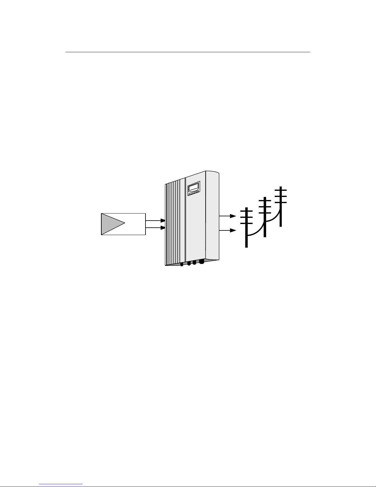
2.1 Grid-
Connected
PV
inverter
......................................................
2
2.2 How to use this
m
a
n
u
a
l
...........................................................
2
3.
S
a
f
e
t
y
I
n
s
t
r
u
c
t
i
o
n
s
............................................................................
3
4
G
e
n
e
r
a
l
Descriptions of
JSI-G1.5K
......................................................
4
4.1 Circuit Description
...................................................................
4
4.2
Features
of
JSI-G1.5K
...............................................................
4
4.3
T
h
e
Wiring
I
n
t
e
r
f
a
c
e
................................................................
5
5
O
p
e
r
a
t
i
o
n
Description
......................................................................
6
5.1
O
p
e
r
a
t
i
o
n
Modes
....................................................................
6
5.2
C
o
mm
i
ss
i
o
n
i
n
g
.......................................................................
6
5.3
R
e
q
u
i
r
e
d
Grid Conditions
.........................................................
7
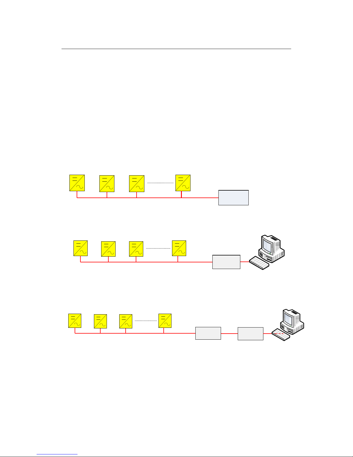
6 Monitoring
and D
i
s
p
l
a
y
.....................................................................
8
6.1
B
a
s
i
c
C
o
mmu
n
i
c
a
t
i
o
n
s
.............................................................
8
6.2
LED
I
n
d
i
c
a
t
o
r
s
.........................................................................
9
6.3
L
C
D D
i
s
p
l
a
y
..........................................................................
10
7
I
n
s
t
a
ll
a
t
i
o
n
.....................................................................................
22
7.1 Checking for Shipping
Damage ..............................................
22
7.2
M
e
c
h
a
n
i
c
a
l
Mounting
............................................................
23
7.2.1
S
a
f
e
t
y
Mounting
I
n
s
t
r
u
c
t
i
o
n
s
...........................................
23
7.2.2
Device Dimensions
and
Weight
.......................................
24
7.2.3
Mounting
R
e
q
u
i
r
e
m
e
n
t
s
..................................................
25
7.3
E
l
e
c
t
r
i
c
a
l
C
o
nn
e
c
t
i
o
n
.............................................................
26
7.3.1
E
l
e
c
t
r
i
c
a
l
C
o
nn
e
c
t
i
o
n
R
e
q
u
i
r
e
m
e
n
t
s
.................................
26
7.3.2
Wires
c
o
nn
e
c
t
i
o
n
...........................................................
27
7.4
C
o
mmu
n
i
c
a
t
i
o
n
I
n
s
t
a
ll
a
t
i
o
n
....................................................
29
7.5
S
t
a
r
t
and
close
......................................................................
30
7.5.1
S
t
a
r
t
the
I
n
v
e
r
t
e
r
............................................................
30
7.5.2
Close the
I
n
v
e
r
t
e
r
..........................................................
30
8
T
e
c
hn
i
c
a
l
D
a
t
a
................................................................................
31
8.1
E
l
e
c
t
r
i
c
a
l
Specifications
..........................................................
31
8.2
M
e
c
h
a
n
i
c
a
l
Specifications
......................................................
31
8.3
Features
...............................................................................
32
9. Appendix
......................................................................................
33
9.1 Exclusion of
L
i
a
b
ili
t
y
..............................................................
33
9.2
Contact
U
s
............................................................................
34