manuals.online logo
Brands
  1. Home
  2. •
  3. Brands
  4. •
  5. Jamara
  6. •
  7. Controllers
  8. •
  9. Jamara COOL RUNNING 081458 User manual

Jamara COOL RUNNING 081458 User manual

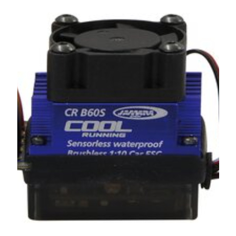
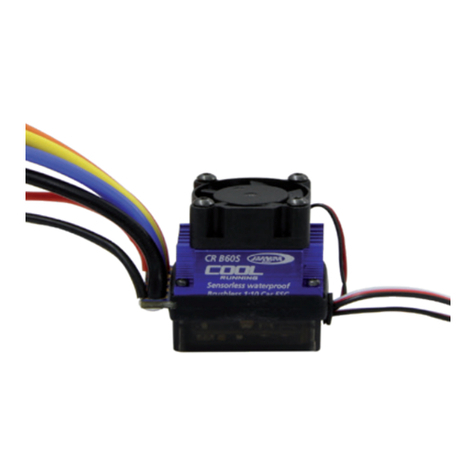
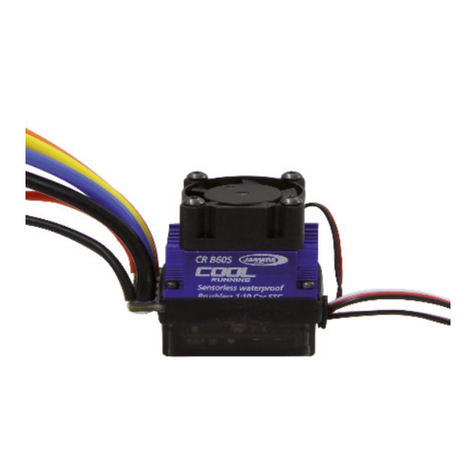
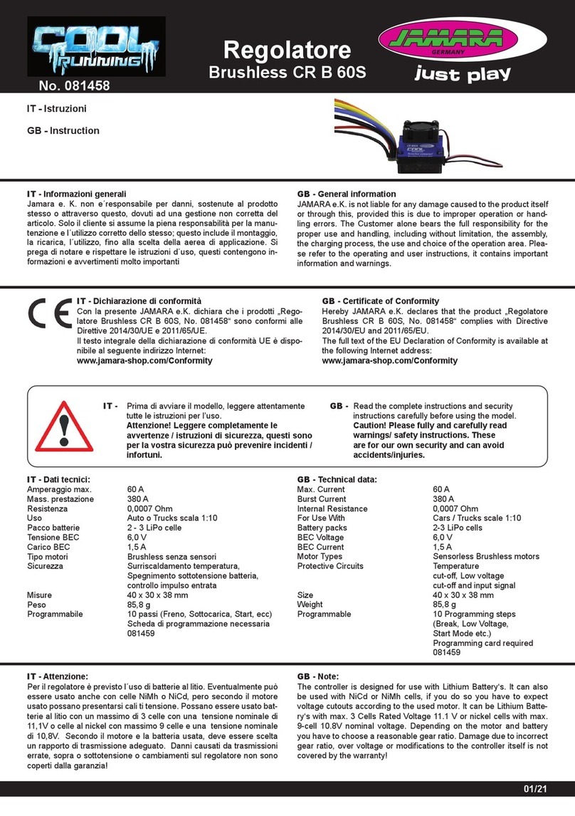
Regulateur
Brushless CR B 60S
No. 081458
FR - Notice d’utilisation
GB - Instruction
FR - Remarques générales
La société Jamara e. K. n’est pas responsable de dommages, que
ce soit au niveau du modèle ou causé par celui-ci, résultant d’une
utilisation non appropriée. Seul le client est responsable concernant
la mise en oeuvre et l’utilisation conforme du matériel; cela va de
l’assemblage, en passant par la charge des accus et allant jusqu’au
domaine d’utilisation. Pour cela, veillez lire attentivement la notice
d’assemblage et d’utilisation, celle-ci contient d’importantes informati-
ons ainsi que les consignes de sécurités.
GB - General information
JAMARA e.K. is not liable for any damage caused to the product itself
or through this, provided this is due to improper operation or hand-
ling errors. The Customer alone bears the full responsibility for the
proper use and handling, including without limitation, the assembly,
the charging process, the use and choice of the operation area. Plea-
se refer to the operating and user instructions, it contains important
information and warnings.
FR - Déclaration de conformité
Par la présente, JAMARA e.K. déclare que les produits „Regu-
lateur Brushless CR B 60S, No. 081458“ sont conformes aux
Directives 2014/30/UE et 2011/65/UE.
Le texte intégral de la déclaration de conformité CE est dis-
ponible via l‘adresse suivante Adresse Internet disponible:
www.jamara-shop.com/Conformity
GB - Certicate of Conformity
Hereby JAMARA e.K. declares that the product „Regulateur
Brushless CR B 60S, No. 081458“ complies with Directive
2014/30/EU and 2011/65/EU.
The full text of the EU Declaration of Conformity is available at
the following Internet address:
www.jamara-shop.com/Conformity
FR - Avant de mettre en marche toute l‘unité il faut lire
attentivement le mode d‘emploi.
Attention! La mise en garde et les consignes de
sécurités sont à lire entièrement pour votre
sécurité et éviter tout accidents et blessures.
GB - Read the complete instructions and security
instructions carefully before using the model.
Caution! Please fully and carefully read
warnings/ safety instructions. These
are for our own security and can avoid
accidents/injuries.
FR - Données techniques:
Courant max. 60 A
Courant adm. faible durée 380 A
Résistance interne 0,0007 Ohm
Domaine d’utilisation Voitures ou Trucks à l’échelle 1:10
Accus 2 - 3 LiPo éléments
Tension BEC 6,0 V
Courant BEC 1,5 A
Types de moteurs Moteurs sans balais
Equipement de sécurité Protection contre la surchauffe,
arrêt du moteur par sous-
tension et contrôle du signal de
commande en entrée
Dimensions 40 x 30 x 38 mm
Poids 85,8 g
Programmable 10 étapes de programmation
(frein, basse tension, mode de
démarrage, etc.)
Carte de programmation
081459 requise
GB - Technical data:
Max. Current 60 A
Burst Current 380 A
Internal Resistance 0,0007 Ohm
For Use With Cars / Trucks scale 1:10
Battery packs 2-3 LiPo cells
BEC Voltage 6,0 V
BEC Current 1,5 A
Motor Types Sensorless Brushless motors
Protective Circuits Temperature
cut-off, Low voltage
cut-off and input signal
Size 40 x 30 x 38 mm
Weight 85,8 g
Programmable 10 Programming steps
(Break, Low Voltage,
Start Mode etc.)
Programming card 081459
required
01/21
FR - Attention:
Le régulateur est prévu pour être utilisé avec des accus au Lithium. Il
est possible de l’utilisé avec des accus du type NiMh ou NiCd, mais
à ce moment la il faut prendre en compte des chutes de tensions en
fonction du moteur utilisé. Vous pouvez utiliser des accus au Lithium
d’un maximum de 3 éléments, 11,1V ou Nickel avec un maximum de
9 éléments donc 10,8V de tension nominale. En fonction du moteur
et de l’accu utilisé il est important de choisir un report de réduction
de la propulsion adapté. Si vous choisissez un mauvais rapport de
réduction, passez en sous-tension ou effectuez des modications du
régulateur, cela n’est pas pris en compte dans la garantie!
GB - Note:
The controller is designed for use with Lithium Battery‘s. It can also
be used with NiCd or NiMh cells, if you do so you have to expect
voltage cutouts according to the used motor. It can be Lithium Batte-
ry‘s with max. 3 Cells Rated Voltage 11.1 V or nickel cells with max.
9-cell 10.8V nominal voltage. Depending on the motor and battery
you have to choose a reasonable gear ratio. Damage due to incorrect
gear ratio, over voltage or modications to the controller itself is not
covered by the warranty!
FR - Options d’alarme des LED:
Signaux d’alerte des LED du régulateur
Message d’erreur couleur de LED Signal de LED
Alarme par sous-ten-
sion (accu vide) LED rouge clignote
Alarme par surchauffe
(95° C) LED orange clignote
GB - ESC’s indicating LEDs:
Sensorless ESC’s Indicating LED
Status of the function Indicating
LED
Status of the
LED
Low voltage
of the battery Red LED Blinking
Over-heat of the ESC
and motor (95°) Orange LED Blinking
FR - Calibration du régulateur
* Avant d’utiliser votre régulateur pour la première fois il faut
calibrer celui-ci.
* Si vous avez changé de récepteur ou si vous utiliser une
nouvelle radio, il faut calibrer le régulateur.
1. Eteignez le régulateur. Branchez le sur la sortie des gaz du
récepteur après s’être assuré que le récepteur et la
radiocommande soient bien synchronisés et que le trimm et le
limiteur de course du servo soient en position neutre,
respectivement en réglage course complète.
2. Restez appuyé sur la touche Setup et mettez en marche le
régulateur. Les LED rouge et orange s’allument. Dès qu’il n’y
a plus que la LED orange qui est allumée, relâchez la touche.
Mettez plein gaz. La LED rouge clignote jusqu’à ce que la
position plein gaz est mémorisée.
3. Placez le manche en position freinage maximal. La LED orange
clignote jusqu’à ce que la position freinage soit mémorisée.
4. Laissez le manche de gaz en position neutre. Les deux LED
clignotent jusqu’à ce que la position neutre soit mémorisée.
5. Eteignez le régulateur.
6. Remettez en marche le régulateur. Celui-ci est maintenant
utilisable.
GB - Throttle Range Calibration
* Set up the ESC at the Throttle Range Calibration for the debut.
* For the rst time using transmitter or changing the transmitter you
must set up Throttle Range Calibration.
1. Switch off the ESC, then connect ESC with the battery packs and
turn on the transmitter; set the direction of the throttle channel to
REV; set the EPA/ATV value of the throttle channel to 100%.
2. Hold the “Switch” button, Red and Blue LED are on solid, wait
for about 2 seconds until the Red LED is off, then release the
“Switch” button, pull the throttle trigger to full throttle until Red
LED blinks and will be on Solid, the motor beeps.
3. Push the throttle trigger to Full Brake until the Blue LED blinks
and will be on solid, the motor beeps.
4. Now return the throttle trigger to the Neutral position, both of the
Red LED and Blue LED blink simultaneously and will be on solid,
the motor beeps. The Throttle Range Calibration is conrmed.
5. Turn off the ESC power switch.
6. Turn the ESC back ON. You are ready to use the ESC now.
FR - Désignation des composants GB - Component description
On/Off
Bouton Setup| Setup button
+
-
+
-
Signal
A
B
C
Connexion moteur
Motor connection
Connecteur de batterie
Battery connection rouge LED | red LED orange LED
2
GB - Programmable items and default settings
Default settings are shown in the grey boxes
Programmable
Items
Programmable Value
1 2 3 4 5 6 7 8 9
Cut-off Voltage 2.6V
cell
2.8V
cell
3.0V
cell
3.2V
cell
3.4V
cell OFF
Running Mode Forward w/o
Reverse
Forward
with pause
then
Reverse
Forward/
Reverse
Motor timing Very Low Low normal High Very High
Initial Acceleration Low Medium High Very High
Throttle Percent Reverse 20% 30% 40% 50% 60% 70% 80% 90% 100%
Throttle Limit 0% 20% 30% 40% 50% 60% 70% 80% 90%
Percentage Braking 10% 20% 30% 40% 50% 60% 70% 80% 100%
Percentage Drag Brake 0% 4% 8% 12% 15% 20% 25% 30%
Motor Rotation Normal Reverse
Neutral Range 2% 3% 4% 5% 6% 10%
3
FR - Valeurs programmables et réglages standards
Les réglages standards sont grisés
.
Points de programmation
Valeurs de programmations
1 2 3 4 5 6 7 8 9
Sous-tension 2.6V
élément
2.8V
élément
3.0V
élément
3.2V
élément
3.4V
élément OFF
Mode de propulsion En avant
uniquement
En avant,
pause,
en arrière
En avant/
En
arrière
Timing moteur Très faible Faible normal Elevé Très élevé
hoch
Accélération Initial Faible medium Elevé Très élevé
Vitesse de recul 20% 30% 40% 50% 60% 70% 80% 90% 100%
Limite gaz 0 % 20% 30% 40% 50% 60% 70% 80% 90%
Force de freinage 10% 20% 30% 40% 50% 60% 70% 80% 100%
Freinage automatique 0% 4% 8% 12% 15% 20% 25% 30%
Rotation du moteur Normal En arrière
Zone neutre 2% 3% 4% 5% 6% 10%
FR - Programmation des réglages
1. Arrêt par sous-tension
Le nombre d’élément est reconnu automatiquement.
En fonction de l’état de l’accu ou de son utilisation il est
important de choisir la bonne tension minimale limite du
régulateur. Le régulateur reconnait automatiquement le
nombre d’éléments composant votre accu au travers de la
tension mesurée et calcule le point de coupure en fonction des
différents paramètres de réglages concernant l’accu utilisé an
de protéger celui-ci contre une décharge trop importante.
2. Mode de marche
• Avance sans frein
Cela est le réglage de compétition pour lequel la marche arrière
est désactivée.
• Avance avec pause puis marche arrière (Standard)
Un réglage permettant d’avoir toutes les fonctions de votre
voiture à disposition.
Attention:
Avec ce type de réglage vous n’avez pas directement accès
à la marche arrière à partir de la marche, il faut tout d’abord
freiner puis placer le manche des gaz en position neutre.
Seulement maintenant la marche arrière est activée. Cela sert
de protection contre les surcharges au niveau de la
transmission.
• Marche avant / arrière
Si cette fonction est activée vous pouvez utiliser la marche
avant ainsi que la marche arrière mais vous n’avez pas de
freinage.
3. Timing moteur
Le Timing inuence directement la puissance rendue et
l’efcacité de votre moteur. Le réglage standard est “normal”
et est une valeur moyenne et utilisable pour la majeure partie
des moteurs brushless.
• Très faible
Permet une efcacité maximale pour une puissance moindre.
Un Timing plus élevé vous procure plus de puissance mais
réduira grandement le rendement et le refroidissement du
moteur. Chaque moteur réagit autrement au Timing. Ce
réglage est idéal pour des moteurs n’ayant pas beaucoup
d’enroulements et des vitesses de rotations (KV) plus élevés.
• Faible
Vous assure assez de puissance pour rouler rapidement sur
piste douce avec un temps d’utilisation sufsant.
• Normal
(Standard) excellent rapport entre efcacité et puissance pour
la plus part des moteurs.
• Elevé
Plus de puissance que d’efcacité avec une durée de fonction
nement moindre. Le moteur devrait être surveillé en
température. Plus la vitesse de rotation est élevée et moins
il y a de nombre d’enroulement ce qui fait que la température
d’utilisation va rapidement montée. Une température maximale
à ne pas dépasser pour le moteur est de l’ordre de 74° à 82°
Celsius. Une température plus élevée va irrémédiablement
endommager votre moteur!
• Très élevé
Cette valeur est utilisée pour obtenir la plus grande puissance
mais doit être utilisé avec beaucoup de précautions!
Veillez observer:
Chaque moteur peut surchauffer. De ce fait contrôlez
régulièrement la température de vote moteur et ne dépassez
jamais les 74° à 82° Celsius. Une température plus élevée va
irrémédiablement endommager votre moteur et peut
également détruire votre régulateur.
4. Comportement à l’accélération
Dans ce chapitre est dénit le comportement du moteur au
démarrage. S vous sélectionnez un réglage très doux votre
véhicule accélérera également très doucement et prendra plus
de temps pour atteindre une certaine vitesse. Au contraire si
vous choisissez la valeur très élevé il est possible que les
pneus n’ont plus assez d’adhérence et tournent dans le vide
mais la vitesse souhaitée est atteinte rapidement. Ce type de
valeur est également lourd à supporter par l’accu de propulsion
du fait que le courant demandé est très élevé. Si votre voiture
à des ratés lors de son utilisation il est vivement conseillé
d’utiliser une valeur plus douce.
• Faible
temps d’utilisation plus long avec une contrainte plus faible sur
l’accu de propulsion. Une très bonne valeur pour les débutants.
• Medium
un peu plus éprouvant pour l’accu pour un démarrage sur
terrain mou.
• Elevé
accélération plus élevée pour une contrainte plus importante
sur l’accu de propulsion.
• Très élevé
accélération la plus élevée entraînant un maximum de
contraintes sur l’accu de propulsion.
5. Puissance maximale pour la marche arrière
Dans ce menu vous pouvez déterminer la vitesse maximale de
marche arrière de votre voiture. 20%, 30%, 40%, 50%,
60%(Standard), 70%, 80%, 90%,1 00%
6. Puissance maximale
Dans ce menu vous pouvez déterminer la puissance maximal
de la marche avant. Plus la valeur en pourcentage est élevée
et plus votre voiture avancera doucement. 0%(pas de
limitation), 20%, 30%, 40%, 50%, 60%, 70%, 80%, 90%
7. Force de freinage
Ici vous dénissez la puissance de freinage de votre véhicule.
10%, 20%, 30%, 40%, 50%(Standard), 60%, 70%, 80%, 100%
8. Puissance de freinage automatique de décélération
0%( Standard), 4%, 8%, 12%, 15%, 20%, 25%, 30%.
Le réglage de la puissance de freinage automatique de
décélération détermine la force avec le véhicule est freiné
lorsque vous placez le manche des gaz en position neutre.
Dans ce cas vous pouvez simuler l’attitude de freinage d’un
moteur à balais. Ce réglage doit être effectué en fonction
du terrain sur lequel vous évoluez. Il est peut-être intéressant
d’utiliser cette fonction sur pour de faibles virages, du fait que le
pilote n’aura pas besoin de freiner d’abord pour atteindre la
bonne vitesse dans chaque virage. Sur un terrain sablonneux
ou glissant il est plutôt judicieux de désactiver cette fonction.
9. Vitesse de rotation du moteur
Normal (Standard), inversé
10. Zone neutre - Ce réglage inuence la zone ‘’d’inactivité’’ du
manche de gaz (zone de neutre) avant que le régulateur ne
réagisse sur les ordres du manche de commande. Plus la
valeur est faible et plus court est la course du manche de
commande pour déclencher la réaction du régulateur au
travers du signal de commande. Plus la valeur est grande et
plus la course est grande.
• 2%
• 3%
• 4% (Standard)
• 5%
• 6%
• 10%
4
GB - Programming the ESC
1. Cutoff Voltage
Automatically detect the number of the cells.
According to the type of your batteries , set up the type of the
batteries and Low Voltage Cutoff Threshold via PC software
or program card. The ESC can detect the Voltage of the battery
anytime and will stop working once the Voltage of the battery is
lower than the preset Low Voltage Cutoff Threshold.
2. Running Mode
• Forward w/o Reverse
This is a Race setting - Reverse is disabled. You will nd in
racing, most tracks will not allow racing with reverse enabled.
• Forward with pause then Reverse: (Default)
General bashing around (FUN) or racing if reverse is allowed
for the event. The Electronic Speed Controller requires 2
seconds of continuous neutral from the transmitter prior to
allowing reverse to operate.
Note:
There is automatic protection within the ESC. Only after you
have stopped and returned the trigger to neutral will reverse
become available. If while traveling in reverse, pull the trigger
to go forward. This is to help prevent serious damage to the
drive train.
• Forward / Reverse
If the option is actived, the RC car could go forward and
backward, but couldn`t brake.
3. Motor Timing
This option affects the power band and efciency (run time) of
an electric motor. The default is “Normal” and is a good starting
point to deliver power and provide good run time.
• Very Low
Provides maximum efciency with less power. Higher timing
produces signicantly more power but at the expense of
efciency (less run time) and typically the motor will generate
more heat. Each brushless motor will respond to timing
differently. Good for running around on paved, or harder
surfaces, and racing with high KV rated or low-turn motors
• Low
Provides power for running through soft surfaces, having fun
and longer run time.
• Normal (Default)
Good mix of power and efciency using any motor
• High More power than efciency so run time will reduce, and
you should be monitoring motor heat. The higher KV or lower
turn motors will generate heat quickly using this setting. A safe
high temperature range is 165F to 180F (74° - 82°C), going
higher may damage your motor.
• Very high
This is maximum power and must be used with caution.
Note:
Any motor has the potential to over-heat in this setting.
Frequently check the motor temperature and make sure you’re
not operating higher than 165° and 180° Fahrenheit
(74°- 82° C), which may damage your motor, or damage your
Electronic Speed Controller (ESC).
4. Initial Acceleration
Use this to limit the initial power that is sent to the motor when
starting from a complete stop.
Using the low option, the vehicle will launch very slowly and
provide the longest run times. When using the HIGH choice,
you will have wheel-spinning acceleration at the cost of run
time. This is also very tough on the batteries as the amperage
draw can be very high. If your vehicle cuts out, hesitates or
loses radio control, you should consider setting this at a lower
value.
• Low
Using this option will provide longer run times and is easiest on
the batteries. It is a good choice for beginners.
• Medium
Medium requires more from your batteries, and is good for low
traction surfaces.
• High
This option will provide full acceleration and requires stout
batteries to supply the load required in this setting.
• Very high
This option will provide full acceleration and requires stout
batteries to supply the load required in this setting.
5. Throttle Percent Reverse
Use this to limit the power available using reverse throttle. The
lower the percent or level the less speed will be available in
reverse. 20%, 30%, 40%, 50%, 60% ( Default), 70%, 80%,
90%, 100%
6. Throttle Limit
The lower the percent the less forward throttle speed will be
available.0%(Default), 20%, 30%, 40%, 50%, 60%, 70%, 80%,
90%
7. Percentage Braking
Gives you the ability to have full control over the amount of
brake your vehicle will have. 10%, 20%, 30%, 40%,
50% (Default), 60%, 70%, 80%, 100%
8. Percentage Drag Brake
0% (Default), 4%, 8%, 12%, 15%, 20%, 25%, 30%
The drag brake function provides the driver a set percentage of
brake when you have the transmitter resting in neutral. This will
create the “feel” of a brushed motor. Drag brake are used in
racing to slow a vehicle as you let off approaching a corner
versus the driver having to push the brake at every corner. Try
working with this to get a sense of how you might use this for
your track. If you are running on a high traction track with tight
corners, a stronger setting should work best. If you are running
in an open area, you will nd a smaller percentage will result in
better control. If you are running in dusty or slippery surfaces,
you will more than likely want to use the lowest option.
9. Motor Rotation
Normal (default), Reverse
10.Neutral Range
This setting adjusts the amount of “Deadband” off neutral on
the throttle trigger. This is in Milli-Seconds (MS) and is the
amount of neutral when you pull the trigger. The smaller the
value the less “Deadband” or movement is required off-center
for the ESC to begin throttle functions. Using a higher value for
this setting will provide a wider Deadband.
• 2%
• 3%
• 4% (Default)
• 5%
• 6%
• 10%
5
FR - Modications manuelles de la programmation du
régulateur
GB - Manuel adjustment of the ESC-Setup
6
Les autres paramètres se modient de la même manière. The rest of programming follows the same procedure
Mettez en marche l’émetteur et le régulateur
Turn on the transmitter and the ESC
Gardez la touche Setup appuyée
Hold the “SET“ button
La LED orange signale 3x en suivant
l’étape de programmation.
Holding Set button,
Orange LED blinks for 3 Cycles
La LED orange clignote 1x
Orange LED blinks for 1 time
La LED orange clignote 2x
Orange LED blinks for 2 time
Relâchez la
touche set
Release
Set button
Relâchez la
touche set
Release
Set button
Appuyez sur
la touche set
Press
Set button
Appuyez sur
la touche set
Press
Set button
Restez appuyé
sur la touche
Setup. La LED
orange 3x en sui-
vant l’étape de
programmation
puis passe à
l’étape suivante.
Holding Set
button, Orange
LED blinks for 3
Cycles
Restez appuyé
sur la touche
Setup. La LED
orange 3x en sui-
vant l’étape de
programmation
puis passe à
l’étape suivante.
Holding Set
button, Orange
LED blinks for 3
Cycles
Phase de programmation 3
sous tension
Enter the 1-nd item
Low voltage cutoff
Phase de programmation 2
mode d’avance
Enter the 2-rd
Running Mode
rouge LED clignote 1x►2,6 V
rouge LED clignote 2x►2,8 V
rouge LED clignote 3x►3,0 V
etc.
Red LED blinks 1x ►2,6 V
Red LED blinks 2x ► 2,8 V
Red LED blinks 3x ► 3,0 V
etc.
LED rouge clignote 1x
► avance avec freinage
LED rouge clignote 2x
► avance pause puis
arrière
LED rouge clignote 3x
► avant/arrière
Red LED blinks 1x
► “forward with brake”.
Red LED blinks 2x
► “forward/reverse with
brake”
Red LED blinks 3x
► “forward / reverse”
La LED orange clignote 3x
Orange LED blinks for 3 time
Relâchez la
touche set
Release
Set button
Appuyez sur
la touche set
Press
Set button
Phase de programmation 2
Timing moteur
Enter 3th Item
Motor Timing
rouge LED clignote 1x
► très faible
rouge LED clignote 2x
► faible
rouge LED clignote 3x
► normal
etc.
Red LED blinks 1x ►
select 2°
Red LED blinks 2x ►
select 4°
Red LED blinks 3x ►
select 6°
etc.
Pour terminer la programmation du régulateur il suft de le mettre hors service puis de le rallumer
Finish programming. Turn off the ESC and then turn it on again.
La LED rouge signale le numéro de la
valeur à programmer.
Enter the corresponding programmable
item, the Red LED blinks for several
times, the time presents the current
value of this item.
Appuyez sur la touche Setup pour
modier la valeur. Le nombre de
clignotement de la LED rouge indique
la valeur.
Press the Set Button to select pro-
grammable value, the Red LED blinks
for several times, the times presents
the serial number of the value you
selected.
FR - Utilisation de la carte de programmation
(disponible en option)
1. La carte de programmation CR avec afcheur à LED vous
facilite grandement la programmation de votre régulateur.
Tous les réglages du régulateur sont directement indiqués
sur l’afcheur de la carte de programmation.
2. Mettez en marche votre régulateur et branchez le câble de
commande sur la carte de programmation (respectez le
sens de branchement indiqué) puis attendez environ 2
secondes jusqu’à ce que l’afcheur de la carte s’allume.
La première étape de programmation est indiquée à gauche.
Si rien ne devait s’afcher, vériez le sens de branchement
du câble de commande et recommencez le processus.
3. Si le régulateur n’est pas connecté à un accu, il est
nécessaire d’alimenter la carte par un accu externe (5 - 6,3V)
(veillez à respecter la bonne polarisation).
4. Appuyez sur la touche “Menu” et passez dans les différents
menus de programmations en appuyant à nouveau sur la
touche. Lorsque l’étape de programmation est atteinte vous
pouvez changer la valeur en appuyant sur la touche „Value“.
La valeur est indiquée sur la partie droite de l’écran. Après
chaque modication il faut conrmer celle-ci en appuyant sur
la touche “OK”. Eteignez le régulateur, les modications sont
sauvegardées d’une manière permanente sur votre
régulateur.
5. Au travers de la touche “Reset” vous pouvez revenir à la
valeur précédente.
GB - Using CR Program card (optional)
1. The Program card with LED display is easy to use and
convenient to carry. All of the programmable functions are
shown on the program card.
2. Turn on the ESC. Remove the Signal wire and plug it into the
top-socket on the Program card , wait for 2 seconds until the
LED is ON.
The rst programmable function will be shown, if an error oc
curs, please reconnect them.
3. If ESC is not connected with the batteries, the Program card
should be connected with other power supply, the range of
power supply is within 5.0-6.3V.
4. Press the button “Menu” on the Program card and circularly
select each programmable function. At that time the number
of the programmable function will be displayed on the left of
the LED, the current value will be displayed on the right side.
Then press the button Value to change the value and press
the button OK to conrm. At the same time the Red indicating
LEDs of both program card and the ESC blink. Turn off the
ESC, the modied settings will be saved in the ESC’s
memory.
5. Press the button Reset to restore the default settings.
FR - Consignes de sécurités
Lors du branchement de l’appareil avec le moteur électrique,
celuici risque de démarrer intempestivement. De plus, les moteurs
déjà connectés à l’accu peuvent se mettre en marche suite à un dé-
faut technique ou mécanique. Cela est également valable si votre
radiocommande n’est pas allumée. Dans ces cas il y a réel danger
de blessure corporelle.
De ce fait, il est absolument déconseillé de ce trouvé dans les en-
virons immédiats des pièces en mouvements. Veillez à ce qu’il n’y
ait pas de pièces qui pourraient toucher les pièces tournantes de
la propulsion. Les propulsions de grande puissance peuvent êtres
extrêmement dangereux. Les forts courants nécessaires à la propul-
sion peuvent faire en sorte que les éléments de l’accu ainsi que
les éléments de commandes chauffent en conséquence. De ce fait
il y a risque d’inammation ou de brûlure de la peau.
Le régulateur est uniquement conçu pour être utilisé dans le
domaine du modèle réduit. N’utilisez jamais ce régulateur avec
une alimentation. Protégez le contre les vibrations, la poussière
ou l’humidité ainsi que contre les contraintes mécaniques. Ne
l’exposez pas à la chaleur ou au froid. Respectez les indications
du fournisseur de votre accu. Vériez régulièrement votre
régulateur s’il n’est pas endommagé. N’effectuez aucune
modication sur votre appareil. Cela est également valable pour le
connecteur d’accu qui ne doit en aucun cas être rallongés.
Le connecteur d’accu n’est pas protégé contre l’inversion de
polarité. Si vous inversez la polarité, votre régulateur sera
irrémédiablement défectueux. La polarité du connecteur est matérial-
isée par une couleur. Branchez le plus sur le câble rouge et le moins
sur le câble noir. Si le moteur devait tourner dans le
mauvais sens, inversez deux des trois connections au niveau du
moteur. N’inversez jamais la polarité au niveau de l’alimentation du
régulateur, cela entraînerait la destruction de celui-ci.
Pour une bonne utilisation de votre régulateur veillez
respecter ces quelques règles:
• N’utilisez que des accus dans les limites des spécications
techniques.
• Laissez le régulateur sufsamment refroidir après l’avoir utilisé.
• Après chaque utilisation, sortez l’accu du modèle.
• Mettez toujours en marche l’émetteur en premier puis le
récepteur, dans l’ordre inverse lorsque vous souhaitez éteindre
l’ensemble.
• N’utilisez que des câbles de liaisons de grande qualité ainsi que
les connecteurs.
• Veillez à avoir toujours une circulation d’air sufsante an de
efroidir correctement le régulateur. Le radiateur qui équipe le
régulateur doit toujours être libre an de pouvoir laisser passer
beaucoup d’air pour assurer un bon refroidissement.
GB -Safety and operating instructions
When connecting an electric motor can cause the unwanted starting
of the engine. Moreover, is it possible that electric motors with
connected power pack can start suddenly because of mechanical or
technical defects. This may cause serious injury.
Because of that it is not allowed that someone is in the near of the
dangerous area around the rotating parts. Take care that no objects
can come in contact with the rotating components of the power drive.
High current can heat up battery, cables and connectors. There may
be re or burns to the skin.
Always use a battery pack to operate the speed controller, never use
a wall power supply. Protect the controller against vibration, dust, mo-
isture and mechanical stress. It neither cold nor excessive
heat from. Consider the specications of the manufacturer of the used
Batteries. Check the controller at regular intervals for damage. At the
regulator may no changes are made. This also applies to the battery
cable, which may in no case extend.
The battery of the controller ports are not protected against reverse
polarity. If the battery connections are reversed, the controller may
be damaged beyond repair. The connecting cables are color coded.
Connect the red to the positive terminal and the black to the negative
terminal of the battery. If the motor runs, it can by swapping two motor
connections, the direction is changed. Never reverse the battery con-
nections, leading to the destruction of the controller.
For the operation of the controller, observe the following safety
instructions:
• Only batteries within the limits of the technical data of the speed
controller. Please note the dates of the corresponding chapter of
this manual.
• Let the controller after use cool well before you start again.
• Remove the battery from the aircraft after each use .
• Turn necessarily on the transmitter rst and then the receiver.
For turn off you go in reverse order.
• Use only high quality cables and connectors.
• Ensure good cooling of the regulator, wrap it in no way a foam
rubber or the like. The attached heat sink must be absolutely
free and are circulated well in air.
7
JAMARA e.K.
Inh. Manuel Natterer
Am Lauerbühl 5 - DE-88317 Aichstetten
Tel. +49 (0) 75 65/94 12-0 - Fax +49 (0) 75 65/94 12-23
[email protected] ●www.jamara.com
Service - Tel. +49 (0) 75 65/94 12-777
kundenservice@ jamara.com
FR - Consignes de recyclage
Les appareils électriques ne doivent strictement pas être jetés dans
les ordures ménagères, mais doivent être jetés séparément. Vous
êtes tenues – dans la possibilité – de déposer vos piles et appareils
électriques dans les centres communaux de collectes. Si des infor-
mations personnelles sont présents sur les appareils électriques,
celles-ci doivent être retirés par vous-même avant tout élimination
du produit.
GB - Disposal restrictions
Electrical appliances must not be disposed of in domestic waste
and must be disposed of separately. You are obliged to take out the
batteries, if possible, and to dispose of the electrical equipment at
the communal collection points. Should personal data be stored on
the electrical appliance you must remove them by yourself.
Irrtum und technische Änderungen vorbehalten. Copyright JAMARA e.K. 2021
Kopie und Nachdruck, auch auszugsweise, nur mit Genehmigung von JAMARA e. K.
All rights reserved. Copyright JAMARA e.K. 2021
Copying or reproduction in whole or part, only with the expressed permission of JAMARA e.K.
FR - Revendeur de service
GB - Service centre
Reitter Modellbau Versand
Patricia Reitter
Degerfeldstrasse 11
72461 Albstadt
Tel 07432 9802700
Fax 07432 2009594
Mail [email protected]
Web www.modellbauversand.de
PenTec s.r.o.
distributor Jamara for Czech Republic and Slovakia
Veleslavínská 30/19
CZ -162 00 Praha 6
Tel +420 235 364 664
Mobil. +420 739 075 380
Mail servis@topdrony.cz
Web www.topdrony.cz
DE
CH
Bay-Tec
Martin Schaaf
Am Bahndamm 6
86650 Wemding
Tel 07151 5002192
Fax 07151 5002193
Mail [email protected]
Web www.bay-tec.de DE
JAMARA e.K.
Manuel Natterer
Am Lauerbühl 5
DE-88317 Aichstetten
Tel +49 (0) 75 65/94 12-0
Fax +49 (0) 75 65/94 12-23
Mail [email protected]
Web www.jamara.com EU
CZ
Modellbau Zentral
Peter Hofer
Bresteneggstrasse 2
CH-6460 Altdorf
Tel +41 79 429 62 25
Mobil. +41 41 870 02 13
Mail [email protected]
Web www.modellbau-zentral.ch

Other manuals for COOL RUNNING 081458

4

Other Jamara Controllers manuals

Jamara COOL RUNNING 081458 User manual

Jamara

Jamara COOL RUNNING 081458 User manual

Jamara COOL RUNNING 081458 User manual

Jamara

Jamara COOL RUNNING 081458 User manual

Jamara COOL RUNNING 081458 User manual

Jamara

Jamara COOL RUNNING 081458 User manual

Jamara Xetronic User manual

Jamara

Jamara Xetronic User manual

Jamara Speed controller CRB60WP User manual

Jamara

Jamara Speed controller CRB60WP User manual

Jamara CR40EP User manual

Jamara

Jamara CR40EP User manual

Jamara COOL RUNNING 081458 User manual

Jamara

Jamara COOL RUNNING 081458 User manual

Jamara CR40EP User manual

Jamara

Jamara CR40EP User manual

Popular Controllers manuals by other brands

TERSUS TC50 user manual

TERSUS

TERSUS TC50 user manual

SEW-Eurodrive EMS operating manual

SEW-Eurodrive

SEW-Eurodrive EMS operating manual

Cooper S280-15-1 Maintenance instructions

Cooper

Cooper S280-15-1 Maintenance instructions

York AMR01M installation manual

York

York AMR01M installation manual

Pixlip 410164 user manual

Pixlip

Pixlip 410164 user manual

OJ Electronics OSA4-10 instructions

OJ Electronics

OJ Electronics OSA4-10 instructions

LTH Electronics MTD75 Operation guide

LTH Electronics

LTH Electronics MTD75 Operation guide

Honeywell Spyder 5 WEB-RxxN Series installation guide

Honeywell

Honeywell Spyder 5 WEB-RxxN Series installation guide

controlair 350 Series Installation, operation and maintenance instructions

controlair

controlair 350 Series Installation, operation and maintenance instructions

ABB PSR manual

ABB

ABB PSR manual

Leuze MSI 200 user manual

Leuze

Leuze MSI 200 user manual

AMALGAMATED INSTRUMENT RM4-LN Operation & instruction manual

AMALGAMATED INSTRUMENT

AMALGAMATED INSTRUMENT RM4-LN Operation & instruction manual

SOMFY SKYMAX animeo WM/DRM 220-240 V AC installation guide

SOMFY

SOMFY SKYMAX animeo WM/DRM 220-240 V AC installation guide

Phasefale JouleAlarm manual

Phasefale

Phasefale JouleAlarm manual

Zeck Audio FOCUS 20CT Service manual

Zeck Audio

Zeck Audio FOCUS 20CT Service manual

Anaheim Automation MDC100-050101USB user guide

Anaheim Automation

Anaheim Automation MDC100-050101USB user guide

ANTEK ECE10CM Series Technical documentation

ANTEK

ANTEK ECE10CM Series Technical documentation

Morningstar ProStar MPPT Series quick start guide

Morningstar

Morningstar ProStar MPPT Series quick start guide

manuals.online logo
manuals.online logoBrands
  • About & Mission
  • Contact us
  • Privacy Policy
  • Terms and Conditions

Copyright 2025 Manuals.Online. All Rights Reserved.