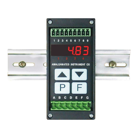
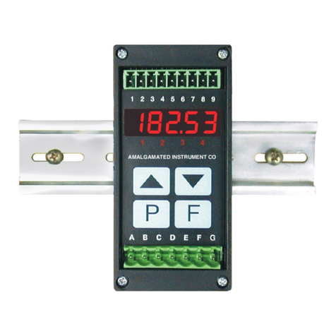
AMALGAMATED INSTRUMENT RM4-LN Administrator Guide

AMALGAMATED INSTRUMENT CO
ACN 001 589 439
PTY
LTD
Telephone:(02)9476 2244
Facsimile: (02) 9476 2902
www.aicpl.com.au
E-mail: sales@aicpl.com.au
AS/NZS
ISO 9001
Lic. No.
QEC 6187
Standards
Australia
Quality
Endorsed
Company
RM4-LN Lineariser
DIN Rail Process Monitor/Controller
Inputs from 0-20mA, 4-20mA,
±100mV, ±1V,±10VC, ±100VDC
or slidewire.
Operation & Instruction Manual

Table of Contents
Introduction . . . . . . . . . . . . . . . . . . . . . . . . . . . . . . . . . . . 3
Mechanical installation . . . . . . . . . . . . . . . . . . . . . . . . . . . . . 4
Electrical installation . . . . . . . . . . . . . . . . . . . . . . . . . . . . . . 5
Signal input connections . . . . . . . . . . . . . . . . . . . . . . . . . 5
Remote input connections. . . . . . . . . . . . . . . . . . . . . . . . . 8
Configuring the input board . . . . . . . . . . . . . . . . . . . . . . . . 8
Explanation of functions . . . . . . . . . . . . . . . . . . . . . . . . . . . 10
Error Messages . . . . . . . . . . . . . . . . . . . . . . . . . . . . . 18
Function table . . . . . . . . . . . . . . . . . . . . . . . . . . . . . . . . . 19
Calibration . . . . . . . . . . . . . . . . . . . . . . . . . . . . . . . . . . . 22
Lineariser operation . . . . . . . . . . . . . . . . . . . . . . . . . . . . . . 24
Lineariser table . . . . . . . . . . . . . . . . . . . . . . . . . . . . . . . . 27
Alarm relays . . . . . . . . . . . . . . . . . . . . . . . . . . . . . . . . . . 28
Easy Alarm Access . . . . . . . . . . . . . . . . . . . . . . . . . . . 30
Alarm mode . . . . . . . . . . . . . . . . . . . . . . . . . . . . . . . 30
Remote input functions . . . . . . . . . . . . . . . . . . . . . . . . . . . . 32
Specifications . . . . . . . . . . . . . . . . . . . . . . . . . . . . . . . . . 34
Technical Specifications . . . . . . . . . . . . . . . . . . . . . . . . . 34
Output Options. . . . . . . . . . . . . . . . . . . . . . . . . . . . . . 34
Physical Characteristics . . . . . . . . . . . . . . . . . . . . . . . . . 34
Setting up the relay PI controller . . . . . . . . . . . . . . . . . . . . . . . 35
Guarantee & Service. . . . . . . . . . . . . . . . . . . . . . . . . . . . . . 42
EL04 25E15 Page 2 of 42 RM4LNMAN-1.4-0

1 Introduction
This manual contains information for the installation and operation of the RM4-LN lineariser
monitor/controller. The RM4 may be configured to accept inputs of0 to 20mA, 4 to 20mA, ±100mV, ±1V,
±10V, ±100VDC or slidewire.
The RM4-LN offers the choice of linear, square root or linearised display. Two separate sets of
calibration scaling values can be stored with the display choice being made via the remote input. In
lineariser operation up to 50 points may be entered. These points and any function settings and scaling
values are stored in EEPROM memory. The lineariser points are stored in a “lineariser table”. A written
copyofthetableshouldbemaintainedforreference, atableisprovided in Chapter8forthispurpose.The
lineariser table stores the display values for each point and the input values (scaled or otherwise)
associated with these display values.
The display may be toggled between “live input” and linearised values via the front ^and v
pushbuttons. The display will indicate INPt priorto a live input reading and Linr prior to a linearised
reading. This featuremaybe used atanytimeto checkthelive input readingsagainstthelineariser table.
The remote input or Pbutton can also be programmed for this display toggling function.
The instrument may be calibratedto display the input in engineering units. Two standard inbuilt
relays provide alarm/control functions. Relay 1 can be configured for basic setpoint operation or for PI
control operation (pulse frequency control or pulse duration control). A standard transmitter supply of
24VDC unregulated is also provided on both AC and DC powered models.
Various combinationsofoneor twooptional extra relays(setpoint operationonly,notPIcontrol),
analog (4-20mA, 0-1V or 0-10V) retransmission/PI control or serial (RS232, RS485 or RS422)
communications and an isolated 12 or 24VDC isolated transmitter supply may also be provided as an
option. Alarms and retransmission may beset to operate from the live input value, the display value or to
followeitherthetare,peakhold,displayhold,peakmemoryorvalleymemoryremoteinputoperations.
Unless otherwise specified at the time of order, your RM4 has been factory set to a standard
configuration.LikeallotherRM4 seriesinstrumentstheconfigurationandcalibrationiseasilychangedby
the user. Initial changes may require dismantling the instrument to alter PCB links, other changes are
made by push button functions.
Full electrical isolation between power supply, input voltage or current and retransmission
output is provided by the RM4, thereby eliminating grounding and common voltage problems. This
isolation feature makes the RM4 ideal for interfacing to computers, PLCs and other data acquisition
devices.The RM4 series of DIN Rail Process Modules are designed for high reliability in industrial
applications. The5 digit LED displayprovides good visibility, even inareas withhigh ambientlightlevels.
A feature of the RM4-IV is the programmable display brightness function, this allows the unit to be
operated with low display brightness to reduce the instrument power consumption and to improve
readability in darker areas. To reduce power consumption in normaluse thedisplay can be programmed
to automatically dim or blank after a set time.
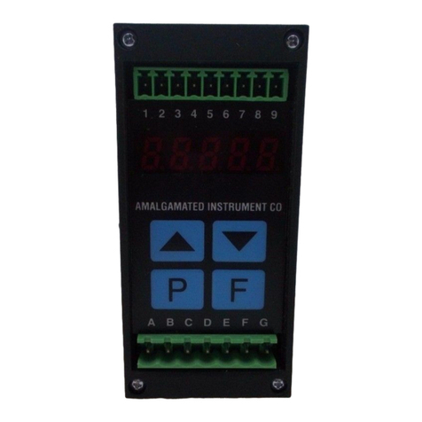
Inputs & outputs
Page 3 of 42 RM4LNMAN-1.3-0
I 2 3 4
Input:
0-20mA,
4-20mA,
±100mVDC,
±1VDC,
±10VDC,
±100VDC,
or slidewire,
link selectable.
Power supply
Two relays configurable as
alarm (on/off) or PI control.
24V transmitter
supply (AC models only).
Optional outputs:
Extra relay.
Two extraalarm relays.
12 or 24V isolated
transmitter supply.
Switched 24Voutput.
Analog retransmission
(single or dual)
Serial communications.
5 digit LED display
Alarm relay annunciator LED's
Pushbutton keypad
2 Mechanical installation
The RM4 is designed for DIN rail, horizontal mounting. The instrument snaps on 35mm DIN
standard rails (EN50022).Cut the DINrailto lengthandinstallwhererequired. To install the RM4, simply
clip onto the rail as shown below. To remove the RM4 lever the lower arm downwards using a broad
bladed screwdriver to pull the clip away from the DIN rail.
Page 4 of 42 RM4LNMAN-1.3-0
44mm
91mm
141mm
4
32I
Rail

3 Electrical installation
The RM4Meter isdesignedfor continuousoperationand nopowerswitchisfittedto theunit.Itis
recommendedthatanexternalswitchandfusebeprovidedtoallowtheunittoberemovedforservicing.
The terminalblocks allowfor wires of upto 2.5mm
2
to be fitted for powersupplyandrelays1 and
2 or 1.5mm
2
for input signal connections and optional outputs. Connect the wires to the appropriate
terminals as indicated below. Refer to other details provided in thismanualtoconfirm proper selectionof
voltage, polarity and input type before applying power to the instrument. When power is applied the
instrument will cycle through a display sequence, indicating the software version and other status
information, this indicatesthat the instrument is functioning. Acknowledgement of correct operation may
be obtained by applying an appropriate input to theinstrument and observing the resultant reading.
3 .1 Signal input connections
Examples continued overleaf.
Page 5 of 42 RM4LNMAN-1.3-0
4
3
2I
Optional outputs GND
12 or 24V transmitter
supply
Input +
Remote input
Not used
Earth
Neutral (DC+)
Active (DC-)
Relay 1
Relay 2
A
C
B
D
E
F
G
5
1
6
2
7
3
8
4
9
RELAY 1
RELAY 2
RELAY 1
RELAY 2
MAINS EARTH
240VAC NEUTRAL
240VAC ACTIVE
REMOTE INPUT
SUPPLY +24VDC
INPUT +VE
GND
RM4-IV-240-5E SERIALNo.
COM
COM
N/O
N/O
Instrument data label (example
)
A
C
B
D
E
F
G
5
1
6
2
7
3
8
4
9
RELAY 1
RELAY 2
RELAY 1
RELAY 2
MAINS EARTH
240VAC NEUTRAL
240VAC ACTIVE
REMOTE INPUT
TRANSMITTER SUPPLY +24VDC
INPUT +
GND
RM4-IV-240-5E SERIAL No.
COM
COM
N/O
N/O
Instrument data label (example)

Page 6 of 42 RM4LNMAN-1.3-0
44
44
33
33
2 2
22
I I
II
4 wire 4-20mA.
Externally powered. 4 wire 4-20mA.
Powered via standard
24V unregulated.
3 wire 4-20mA.
Powered via standard
24V unregulated.
2 wire 4-20mA.
Powered via standard
24V unregulated.
Transmitter Transmitter
Shield Shield
Shield
Shield
External power
supply Supply
Supply
Signal
Signal
+
+
+
+
+
+
+
-
-
-
-
-
-
Ensure that link
settings correspond
to input type
Ensure that link
settings correspond
to input type
Ensure that link
settings correspond
to input type
Ensure that link
settings correspond
to input type

Page 7 of 42 RM4LNMAN-1.3-0
44
44
33
33
22
22
II
II
Ensure that link
settings correspond
to input type
Ensure that link
settings correspond
to input type
Ensure that link
settings correspond
to input type
Ensure that link
settings correspond
to input type
2 wire 4-20mA.
Externally powered.
2 wire 4-20mA.
Powered via optional
12 or 24V regulated.
DC voltage input Slidewire input
Transmitter Transmitter
Sensor
Shield Shield
ShieldShield
External power
supply
++
+
-
+
--
-

3 .2 Remote input connections
Theselected remote input functioncanbeoperated via an external contactclosure via a switch,
relay or open collector transistor switch.
A momentary action is required for functions such as tARE and ZERO, a latching switch or
normally closed momentary switch may be required for functions such as peak hold.
3 .3 Configuring the input board
Remove the circuit board from the case following the instructions below.
Page 8 of 42 RM4LNMAN-1.3-0
Remove the connectors,
the four front bezel screws
and the earth screw
at the side of the case.
Hold the front bezel and
slide out the circuit boards.
43
2
I
Remote
input
Choose momentary or
latching switch to
suit function selected.

Link settings for the main input board are as shown below. For optional output link settings
consult the appropriate appendix in this manual.
Page 9 of 42 RM4LNMAN-1.3-0
Main circuit board
±100mV
links
±100V
links
Both links
in for 24V
transmitter
supply
Both links
must be out
for slidewire
operation
±1V
links
0-20mA or
4-20mA links ±2mA
links
±10V
links
Slidewire
links
TX SUPPLY

4 Explanation of functions
The RM4 setup and calibration functions are configured through a push button sequence. Two
levels of access are provided for setting up and calibrating:-
FUNC mode(simple pushbuttonsequence)allowsaccesstoalarmrelay,presetvalue& display
brightness functions.
CAL mode (power up sequence plus push button sequence) allows access to all functions
including calibration parameters.
Pushbuttonslocatedatthefrontoftheinstrumentareusedtoaltersettings.Once CAL orFUNC
modehasbeenenteredyoucanstepthroughthefunctions,bypressingandreleasingtheFpushbutton,
until therequiredfunctionisreached.Changestofunctionsaremadebypressingthe ^or vpushbutton
(in some cases both simultaneously) when the required function is reached.
Page 10 of 42 RM4LNMAN-1.3-0
Entering Mode
CAL Entering ModeFUNC
1. Remove power from
the instrument. Hold in the
button and reapply power.
The display will indicate
as part of the
"wake up messages" when
the message is seen
you can release the
button.
2.When the "wake up"
messages have finished
and the display has settled
down to its normal reading
press, then release the
button.
1.When the "wake up"
messages have finished
and the display has settled
down to its normal reading
press, then release the
button.
3.Within 2 seconds of
releasing the button
press, then release
the and buttons
together.The display will
now indicate followed
by the first function.
2.Within 2 seconds of
releasing the button
press, then release
the and buttons
together.The display will
now indicate followed
by the first function.
^
^
^^
FUNC
FUNC
F
F
F
FF
CAL
CAL
Note: If step1 above has beencompleted then the
instrument will remain in this mode state until
power is removed. i.e. there is no need to repeat step 1
when accessingfunction unless power hasbeen removed.
CAL
No special power up procedure
is required toenter mode.FUNC

Function Range Description
C.SEt -19999
to 99999 Analog controlsetpoint - seen onlywhentheanalog retransmissionoption
is fitted and REC ctrI is set to on. Refer to theseparate “RM4 DINRail
Meter Optional Output Addendum” booklet supplied when this option is
fitted.
A1.SP -19999
to 99999 Alarmrelay1controlsetpoint.SeenonlywhenA1 OPER issetto A1.tP or
A1.Fr. See “Setting up the relay PI controller” appendix.
AxLo -19999
to 99999
or OFF
Alarm relay low setpoint - see “Alarm relays” chapter.
Displays and sets each alarm low setpoint value. Note "x" will show up as
the relay number e.g. A1Lo etc.
AxHi -19999
to 99999
or OFF
Alarm relay high setpoint - see “Alarm relays” chapter.
Displays and sets eachalarm high setpoint value.Note "x" will show up as
the relay number e.g. A1Hi etc.
AxHy 0 to 9999 Alarm relay hysteresis [deadband]) - see “Alarm relays” chapter.
Displays andsetsthe alarmhysteresis limit.Thisvalue iscommon forboth
high and low setpoint values. Note "x" will show up as the relay number
e.g. A1HY etc.
Axtt 0to 9999 Alarm relay trip time - see “Alarm relays” chapter.
Displays and sets the alarm trip time in seconds/tenths of seconds. This
value is common for both alarm high and low setpoint values. Note "x" will
show up as the relay number e.g. A1tt etc.
Axrt 0to 9999 Alarm relay reset time - see “Alarm relays” chapter.
Displays and sets thealarmreset time in seconds/tenthsof seconds. This
value is common for both alarm high and low setpoint values. Note "x" will
show up as the relay number e.g. A1rt etc.
Axn.o
or
Axn.c
Axn.o or
Axn.c Alarmrelaynormallyopenornormallyclosed-see“Alarmrelays”chapter.
Displays and sets the alarm relay action to normallyopen (de-energised)
ornormally closed (energised) when no alarm condition is present. Note
"x" will show up as the relay number e.g. A1n.o etc.
A2.SP,
A2.t1,
A3.t2
etc.
A2.SP,
A2.t1,
A3.t2 etc.
Alarm relay operation independent setpoint or trailing - see “Alarm relays”
chapter.
brgt 1 to 15 Display brightness - displays and sets the digital display brightness. The
display brightness is selectable from 1to 15 where 1= lowest intensity
and 15 = highest intensity. This function is useful for reducing glare in
darkened areas.
duLL 0 to 15 Remote display brightness - displays and sets the level for remote input
brightness switching, see "Remote input functions" chapter. See also
d.OFF SECS function below.
d.oFF
SECS
0to 9999
seconds Autodisplaydimmingtimer-thisfunctionallowsatimetobesetafterwhich
thedisplay brightness (set by the brGt function) will automatically be set
to the level set at the duLL function. The auto dimming feature can be
used to reduce power consumption. The function can be set to any value
between 0and 9999 seconds. A setting of 0disables the auto dimming.
Thedisplay brightness canbe restored by pressinganyofthe instruments
front push buttons. The display brightness will also be restored whilst one
or more alarm relays is activated.
CAL mode functions
Entry via CAL mode must be made in order to view and adjust the functions which follow.
Alternativeley setting ACCS function to all will allow access to these funcitons.
A1
OPER
A1AL,
A1.tP or
A1.Fr
Alarm relay 1 operation mode - sets the mode of operation for relay 1.
Choices are A1.AL (setpoint relay operation), A1.tP (time period PI
control operation) or A1.Fr (frequency PI control operation).
Page 11 of 42 RM4LNMAN-1.3-0

ctrI
SPAN
1to
99999 PI relay control span - seen only when the A1 OPER is set to A1.tP or
A1.Fr. See “Setting up the relay PI controller” appendix.
A1. PG -19.999
to 32.767 PIrelayproportional gain- seenonlywhenthe AxOPER issetto Ax.tPor
Ax.Fr. See “Setting up the relay PI controller” appendix.
A1.IG -19.999
to 32.767 PI relay integral gain - seen only when the A1 OPER is set to A1.tP or
A1.Fr. See “Setting up the relay PI controller” appendix.
A1.IL 0.0 to
100.0 PIrelayintegrallowlimit-seenonlywhenthe A1 OPER issettoA1.tPor
A1.Fr. See “Setting up the relay PI controller” appendix.
A1.IH 0.0 to
100.0 PIrelay integral high limit - seen only when the A1 OPER isset to A1.tP
or A1.Fr. See “Setting up the relay PI controller” appendix.
A1.bS 0.0 to
100.0 PI relay bias - seen only when the A1 OPER is set to A1.tP or A1.Fr.
See “Setting up the relay PI controller” appendix.
A1.dc 0 to 250 PI relay duty cycle - seen only when the A1 OPER is set to A1.tP or
A1.Fr. See “Setting up the relay PI controller” appendix.
A1.dr 0.0 to
25.0 PI relay duration - seen only when the A1 OPER is set to A1.Fr. See
“Setting up the relay PI controller” appendix.
rEC_ -19999
to 99999 Analog recorder/retransmission output low value - seen only when the
analogretransmission option isfitted.Refer to theseparate“RM4DIN Rail
Meter Optional Output Addendum” booklet supplied when this option is
fitted.
Displays and sets the analog retransmission output low value (4mA or 0V)
in displayed engineering units. e.g. for a 4-20mA retransmission if it is
required to retransmit 4mAwhen the display indicates 0then select 0at
this function via the ^or vbutton.
rEC~ -19999
to 99999 Analog recorder/retransmission output high value - seen only when the
analogretransmission option isfitted.Refer to theseparate“RM4DIN Rail
Meter Optional Output Addendum” booklet supplied when this option is
fitted.
Displays and sets the analog retransmission output high value (20mA, 1V
or 10V) in displayed engineering units. e.g. if it is required to retransmit
20mAwhen the display indicates 500 then select 500 at this function via
the ^or vbutton.
rEC_
Ch 2
-19999
to 99999 Second analogrecorder/retransmissionoutputlowvalue-seenonlywhen
the dual analog retransmission option is fitted. See REC_ function for
descriptionofoperation.Seealso REC2 function(analogoutput2mode).
rEC~
Ch 2
-19999
to 99999 Second analog recorder/retransmission output high value - seen only
when the dual analog retransmission option is fitted. See REC~ function
for description of operation. See also REC2 function (analog output 2
mode).
drnd 0 to 5000 Displayrounding -displaysandsetsthedisplayroundingvalue.Thisvalue
may be set to 0 - 5000 displayed units. Display rounding is useful for
reducing the instrument resolution without loss of accuracy in applications
where itis undesirable to display to a fine tolerance. (example: if set to 10
the instrument will display in multiples of 10).
dCPt 0 to
0.0004 Decimal point selection - displays and sets the decimal point. By pressing
the^or vkeypadsthe decimal pointpositionmaybe set.Thedisplaywill
indicateasfollows:0(nodecimalpoint),0.1 (1 decimal pointplace),0.02
(2 decimal point places), 0.003 (3 decimal point places) or )0004 (4
decimal point places).
FLtr 0 to 8Digitalfilter -displays andsetsthe digitalfilter value.Digital filtering is used
forreducingsusceptibilitytoshortterminterference.The digitalfilter range
is selectable from 0to 8, where 0= none and 8= most filtering. A typical
value for the digital filter would be 3. The digital filter uses a weighted
averaging method offilteringwhichwillincrease the displayupdate time at
higher settings.
REC
ctrI
on or OFF Analog control on or off - seen onlywhentheanalog retransmissionoption
is fitted. Refer to the separate “RM4 DIN Rail Meter Optional Output
Addendum” booklet supplied when this option is fitted.
Page 12 of 42 RM4LNMAN-1.3-0

C.SPN 0 to
99999 Control span - seen only when the analog retransmission option is fitted
and REC ctrI is set to on. Refer to the separate “RM4 DIN Rail Meter
Optional Output Addendum” booklet supplied when this option is fitted.
C. PG -19.999
to 32.767 Control proportional gain - seen only when the analog retransmission
optionisfittedandRECctrI issettoon.Refertotheseparate“RM4DIN
Rail Meter Optional OutputAddendum” booklet supplied when this option
is fitted.
C. PO 0.0 to
100.0 Control proportional offset - seen only when the analog retransmission
optionisfittedandRECctrI issettoon.Refertotheseparate“RM4DIN
Rail Meter Optional OutputAddendum” booklet supplied when this option
is fitted.
C. IG -19.999
to 32.767 Control integral gain - seen only when the analog retransmission option is
fitted and REC ctrI is set to on. Refer to the separate “RM4 DIN Rail
Meter Optional Output Addendum” booklet supplied when this option is
fitted.
CIL.H 0.0 to
100.0 Control integral limit high - seen only when the analog retransmission
optionisfittedandRECctrI issettoon.Refertotheseparate“RM4DIN
Rail Meter Optional OutputAddendum” booklet supplied when this option
is fitted.
CIL.L 0.0 to
100.0 Controlintegrallimitlow-seenonlywhentheanalogretransmissionoption
is fitted and REC ctrI is set to on. Refer to the separate “RM4 DIN Rail
Meter Optional Output Addendum” booklet supplied when this option is
fitted.
REC
SPAC
on or OFF Control setpoint access on or off - seen only when the analog
retransmission option is fitted and REC ctrI is set to on. Refer to the
separate “RM4 DIN Rail Meter Optional Output Addendum” booklet
supplied when this option is fitted.
CAL1 &
CAL2 n/a Calibration scaling points - see “Calibration” chapter.
Displays andsetsthe independentcalibration/scalingpointsofthe input to
the display. See “Calibration” chapter for full details of setting up.
CAL
OFSt
-19999
to 99999 Calibration offset - the calibration
offset is a single point adjustment
which can be used to alter the
calibration scaling values across
the entire measuring range without
affecting the calibration slope.
This method can be used instead of
performing a two point calibration
when a constant measurement
error is found to exist across the
entire range. To perform a calibration
offset press the ^and vbuttons
simultaneously at the CAL OFSt
function. A "live" reading from the
input will be seen, make a note of
this reading. Press the Fbutton, the message SCLE will now
beseenfollowedbythe lastscalevalue in memory.Usethe^orvbutton
to adjust the scale value to the required display value for that input.
For example if the "live" input reading was 50 and the required display
value for this input was 70 then adjust the SCLE value to 70.
Page 13 of 42 RM4LNMAN-1.3-0
Input
offset
offset

ZERO
RNGE
-19999
to 99999
or OFF
Zero range - the zero range function allows a limit value to be set (in
engineering units) above which the display will not zero i.e. if a zero
operation is attempted via the Pbutton, remote input or setzero function
when the display value is greater than the zero range setting the display
will refuse to zero and give a ZERO RNGE Err message (note that the
CAL OFSt function is also affected by the ZERO RNGE setting). For
exampleif the zero rangesettingis10theinstrumentwill only respondto a
zero operation if the display reading at the time is between -10 and 10. If
thezerorange function isnotrequiredit can be set toOFF bypressingthe
^and vbuttons simultaneously at this function. When switched off the
instrument can be zeroed no matter what the display value.
Note that the instrument keeps track of the value being zeroed at each
operation, when the total amount zeroed from repeated operations
becomes greater than the zero range value the instrument will reject the
zerooperationand aZERO RNGE Err messagewillbe seen.To allowa
zerooperationbeyond thispointeithertheZERO RNGE functionvaluewill
need to be raised or a new zero reference point introduced via the CAL
ZERO function.
If repeated zero operationsare required the ZERO RNGE function should
be set to OFF or alternatively the tARE operation could be considered.
CAL
ZERO n/a Calibration zero - the calibration zero function is used following a
calibration via CAL1 and CAL2. A calibration zero operation at this time
ensures that the display zero and the ZERO RNGE reference zero are at
the same point after a calibration. After a calibration the calibration zero
can also be used to select a zero point other than the display zero as the
reference for the ZERO RNGE function. For example if the CAL ZERO
operation is carried out witha display reading of 500 and a ZERO RNGE
readingof10thezerorangefunctionwillallowthedisplaytozeroonlyifthe
current display reading is between 490 and 510. Toperform a calibration
zero press the ^and vbuttons simultaneously at the CAL ZERO
function,alivereading willbe seen,presstheFbutton,themessageCAL
ZERO End should now be seen indicating that the instrument has
accepted the zero point. Although the display readingwillnot change as a
resultof thecalibration zerothe input value onthedisplayatthetimeof the
operation will be the new zero reference point for the ZERO RNGE
function.
USER
En 4
-19999
to 99999 4mA input scaling without a live input - see “Calibration” chapter. This
calibration method can be used with 4-20mA inputs only. The instrument
can be scaled for a 4-20mA input without a live input i.e. this is an
alternative method to the CAL1 and CAL2 method of scaling.
USER
EN20
-19999
to 99999 20mA input scaling without a live input - see “Calibration” chapter. This
calibration method can be used with 4-20mA inputs only. The instrument
can be scaled for a 4-20mA input without a live input i.e. this is an
alternative method to the CAL1 and CAL2 method of scaling.
UCAL n/a Uncalibration- see “Calibration” chapter. Used to set the instrument back
to the factory calibration values.
P.but NONE,
Hi,
Lo, HiLo,
tARE or
ZERO
Pbutton function - the function of the Pbutton is programmable in the
same manner as the remote input (see R.INP below). The Pbutton
selectionwill override theselectionmade under theR.INP function ifboth
have the same functions selected. Uponreaching the P.but function the
choices shown below are available, see "Remote input functions" chapter
fora fulldescription of eachchoice. Note: To preventaccidental operation
ofthe Pbutton in the tArE or ZERO functions it is necessary to hold the
button in for approx. 2seconds to perform the selected operation.When in
Lo, Hi orHiLo thehigh/low values held in memory can be reset (i.e. the
memory is cleared) by holding the Pbutton pressed for 2 seconds.
Choices available for the Pbutton function are:
NONE No function, Hi Peak memory, Lo Valley memory, HiLo Toggles
between peak and valley memory, tARE Push button tareor nettor gross
display function (toggles), ZERO Pushbutton zero, dISP Allows toggling
via the Pbutton between the live input value (preceded by the message
INPt)andthelinearisertablevalue(precededbythemessageLinr).
Page 14 of 42 RM4LNMAN-1.3-0

R.INP NONE,
P.HLd,
d.HLd,
Hi, Lo,
Hi Lo,
tARE,
ZERO,
SP.Ac,
No.Ac,
CAL.s,
dISP or
duLL
Remote input - displays and sets the special function input selection, see
“Remote input functions” chapter.
Nett
FLSH
on or OFF Nett value display mode - The nett value is only seen when the remote
input or Pbuttonis usedto toggle betweenthe nettandgrossvalues. The
NEtt FLSH function can be set to on or OFF. If set to on then the
message NEtt willflash briefly approximately every 6 secondswhenthe
operatortoggles to anettdisplayto remind the operator thata nettvalueis
being viewed. If set toOFF then themessageNEtt will flash brieflyonce
only when the operator toggles to the nett value.
ACCS OFF,
EASY,
NONE or
ALL
Alarm relay access mode - see “Alarm relays” chapter.
SPAC A1, A1-2
etc. Setpoint access - sets the FUNC mode access to the alarm relays set
points.Thefollowing choices are available;A1 - Allows setpoint accessto
alarm1only.A1-2 -Allows accessto alarms1and 2only.A1-3 -Allows
access to alarms 1, 2 and 3only etc. up to the maximum number of relays
fitted. To allow this function to operate the remote input R.INP function
must be set to SPAC.
SQrt on or OFF Square root- selects thesquarerootscalingtoon orOFF.Whensettoon
a square root function is applied to the input. When set to OFF the
calibration is a linear function. Note: It is essential that the display is
rescaled, using CAL1 and CAL2 or USER En 4 and USER EN20,
whenever the square root function is turned on or off.
Whenthesquarerootfacilityisused thescaleddisplayedvaluefollowsthe
square root of the percentage of the full scale input value. The upper and
lower input limits are set as normal as are the values to be displayed at
these limits. For example if, for a 4 - 20mA input, you wish to display 0at
4mAand1000 at20mAthesquarerootfunctionwillcalculateasfollows:
At 20mA (100%) the display will be 1000 i.e. 1 1000x.
At 16mA (75%) the display will be 866 i.e. 075 1000. x.
At 12mA (50%) the display will be 707 i.e. 050 1000. xetc.
tAbL
tabL
StOP
SCLE
tbIE
tAbL
PntS
SEt
tAbL
Lineariser funcitons. See “Lineariser operation” chapter
AI to
A4
LiuE,
tARE,
P.HLd,
d.HLd, Hi,
Lo or
dISP
Alarm mode - The alarms can be set to operate from the live input value
(LiuE), the tare value (tARE), the peak hold value (P.HLd), the display
hold (dHLd), the peak memory (Hi) or the valley memory (Lo). Ensure
that the R.INP orP.but function is also set to the desired operation. See
“Alarm relays” chapter for further information.
If the linearising table is
turned on then the Liue value will be the
linearised value.
Page 15 of 42 RM4LNMAN-1.3-0

REC LiuE,
tARE,
P.HLd,
d.HLd,
Hi, Lo or
dISP
Analog retransmission mode - The description below applies to both the
analog retransmission mode (4-20mA or DC Volts) and the serial (RS232
or RS485) communications. The serial communications mode is set via
the SERL function. Refer to the separate “RM4 DIN Rail Meter Optional
Output Addendum” booklet supplied when this option is fitted. The
following choices are available for analog or serial retransmission
operation mode:
LiuE - live input mode.
If the linearising table is turned on then the
Liue value will be the linearised value.
The retransmission will follow
the electrical input and will not necessarily follow the 7 segment display.
Forexampleiftheremoteinputissetforpeakholdoperationthenwhenthe
remote input is closed the7segmentdisplaywillonlyshowthe peak value
buttheretransmissionwillbefreetochangetofollowtheelectricalinput.
tARE - tare mode. The retransmission value will tare (fall to zero) along
with 7 segment display when the remote input tare function is operated. If
theremoteinput togglesthe7segmentdisplaytoshowgross(GROS)then
the 7 segment display will change to show the gross value but the
retransmission will not respond (see LiuE for alternative operation).
P.HLd -peakholdmode.The7segmentdisplayandretransmissionvalue
will indicate the peak valueonly whilst the peak valuefunction is operated
via a contact closure on the remote input i.e. the 7 segment display and
retransmissioncanrise butnot fallwhilsttheremote input switchis closed.
When the remote input switch is opened the retransmission value will
remain fixed i.e. it willnot rise or fall, although the7 segmentdisplay value
will be free to alter. This peak retransmission output can be cleared by
closingtheremoteinputswitchforanotheroperationorbyremovingpower
fromthe instrument. Note:Inthismodetheretransmissionwillshowazero
readinguntiltheremoteinputisoperatedforthefirsttimeafterswitchon.
d.HLd - display hold mode. The 7 segment display and retransmission
value will be held whilst the remote input display hold switch is closed.
Whentheswitchisopenedtheretransmissionvaluewillremainfixedatthe
held value although the 7 segment display value will be free to alter. The
held retransmission output can be cleared by closing the remote input
switch for another operation or by removing power from the instrument.
Hi - peak (max.) memory mode. With the peak remote input switch open
the retransmission will indicate the peak value in memory i.e. the
retransmission output can rise but not fall. The retransmission output can
be reset by clearing the memory. The memory may be cleared either by
closing the remote input switch for approximately 2 seconds or by
removing power to the instrument.
Lo -valley(min.) memorymode. Withthe valleyremoteinput switchopen
the retransmission will indicate the valley (min.) value in memory i.e. the
retransmission output can fall but not rise. The retransmission output can
be reset by clearing the memory. The memory may be cleared either by
closing the remote input switch for approximately 2 seconds or by
removing power to the instrument.
dISP - display mode. The retransmission output will follow whatever
value is on the 7 segment display. For example if theremote input is set to
tARE thenthe7segmentandretransmissionoutputwill indicate thetared
value andbothwill alsobe changediftheremoteinputtogglesthe displays
between nEtt and GROS. If the REC function had been set to tARE
rather than dISP thentheretransmission outputwould not respondtothe
GROS toggle.
REC2 See above Analog retransmission mode for optional second analog output - see REC
function for description. Refer to the separate “RM4 DIN Rail Meter
Optional Output Addendum” booklet supplied when this option is fitted.
Lo
dISP Value or
OFF Low overrange limit value - the display can be set to show an overrange
messageifthedisplayvaluefallsbelowtheLo dISP setting.For example
if Lo dISP is set to 50 then once the display reading falls below 50 the
message-or- or thedisplayvalue(seedISP function)will flash instead
ofthenormaldisplay units.Thismessage canbeusedto alert operatorsto
thepresence of an input which is below the low limit. If this function is not
required it should be set to OFF by pressing the ^and vbuttons
simultaneously at this function.
Page 16 of 42 RM4LNMAN-1.3-0

HIGH
dISP Value or
OFF High overrange limit value - the display can be set to show an overrange
message if the display value rises above the HIGH dISP setting. For
exampleifHIGH dISP issetto1000 thenoncethedisplayreading rises
above 1000 the message -or- or the display value (see dISP
function) will flash instead of the normal display units. This message can
beused to alert operators to the presence of an input which is above the
high limit. If this function is not required it should be set to OFF.
dISP FLSH or
-or- Display overrange warning flashing mode - this function is used in
conjunction with the Lo and HIGH dISP functions. The dISP function
can be set to FLSH or -or-. If the value set at the Lo or HIGH dISP
function is exceeded and the dISP function is set to FLSH then the
display value will flash on for approximately one second and off for
approximately one second as a warning. If the value set at the Lo or
HIGH dISP function is exceeded and the dISP functionis set to -or-
then the -or- message will flash on for approximately one second and
off for approximately one second as a warning. The warning flashes will
cease andthenormaldisplay value will be seen whenthevaluedisplayed
is higher than the low limit and lower than the high limit.
bAud 300, 600,
1200,
2400,
4800,
9600,
19.2 or
38.4.
Set baud rate - seen only with serial output option - Refer to the separate
“RM4 DIN Rail Meter Optional Output Addendum” booklet supplied when
this option is fitted.
Select from 300, 600, 1200, 2400, 4800, 9600, 19.2 or 38.4.
Prty NONE,
EUEN or
odd.
Setparity- seen onlywith serialoutput option -Referto the separate“RM4
DIN Rail Meter Optional Output Addendum” booklet supplied when this
option is fitted.
Select parity check to either NONE, EUEN or odd.
O.Put diSP,
Cont,
POLL,
A.buS or
M.buS
Set RS232/485 interface mode - Refer to the separate “RM4 DIN Rail
Meter Optional Output Addendum” booklet supplied when this option is
fitted.
Select diSP,Cont, POLL, A.buS or M.buS
Allows user to select the RS232/485 interface operation as follows:-
disP Sends imagedata from the display
without conversion to ASCII.
Cont Sends ASCII form of display data
every time display is updated.
POLL Controlled by computer or PLC as host.
Host sends command via RS232/485 and
instrument responds as required.
A.buS A special communications mode used with Windows
compatible optional PC download software.
Refertotheusermanualsuppliedwiththisoptionalsoftware.
M.bus Modbus RTU protocol.
Addr 0to 31 Set unit address for polled (POLL, A.buS or M.buS) mode (0 to 31)) -
Refer to the separate “RM4 DIN Rail Meter Optional Output Addendum”
booklet supplied when this option is fitted. Note: address 0 should not be
used in modbus mode.
Allows several units tooperate on the same RS485 interface reporting on
different areas etc. The host computer or PLC may poll each unit in turn
supplying the appropriate address.
The unit address ranges from 0 to 31 (DEC) but is offset by 32 (DEC) to
avoid clashing withASCIIspecialfunctioncharacters(suchas <STX>and
<CR>). Therefore 32 (DEC) or 20 (HEX) is address 0, 42 (DEC) or 2A
(HEX) addresses unit 10.
Page 17 of 42 RM4LNMAN-1.3-0

SERL LiuE,
tARE,
P.HLd,
d.HLd,
Hi, Lo,
dISP or
HiLo
Serial communications output mode - see REC function for description.
Refer to the separate “RM4 DIN Rail Meter Optional Output Addendum”
booklet supplied when this option is fitted.
Returning to the normal measure mode
Whenthecalibrationprocedurehasbeencompleteditisadvisabletoreturntheinstrumenttothe
normal mode (where calibration functions cannot be tampered with). To return to the normal mode, turn
off power to the instrument, wait a few seconds and then restore power.
4 .1 Error Messages
Linr tbIE Err -lineariser table entryerror. Thismessage indicates thatthere isanerror inthe
figuresinthetablee.g.allPand Yvaluesareidentical. Return totheSEttAbL functionandcheck
the entries.
SPAN Err - scaling span error. This message indicates that the live inputs used in CAL1 and
CAL2 were either identical or too close together. Recalibrate ensuring that the live input used at
CAL1 is significantly different to that used at CAL2.
CAL FAIL -scaling failure. This message indicates that theinstrument has not accepted the live
inputs used during a CAL1 and CAL2 scaling operation. Try recalibrating again ensuring that the
inputsusedarecorrectforthe inputrange andinputlinksettingschosen,youmayfindthattheinput
linkshavebeensetto adifferentrange. Ifyou have checkedthe inputsand find that theCAL FAIL
messageisstill appearingthenperforma UCAL operationpriortotheCAL1 andCAL2 operation.
COP FAIL - this message indicatesthatthe instrumentpowerhas beeninterrupted, usuallyduea
spike on the power supply or signal input lines. The instrument will show this error message and
then reset itself i.e. the “wake up” display messages will be seen after the COP FAIL message.
Check the power supply and input lines for spikes, usually caused by something with a large
inductance (e.g. solenoid, motor etc.) on the same supply circuit switching on or off. It may be
necessary to suppress the interference at the source and/or place the RM4 on a different supply
line. Screened cables are recommended for the signal inputlines, the screen shouldbe grounded
at the RM4 end only.
----— the bars across the screen indicate that the instrument is seeing an input which is out of its
range. e.g. if the input links are set to 0-1V and the signal input is much greater than 1V then this
error message will be seen. Check the input signal and input links.
-or- this message indicates that the display is “overrange” i.e. it is being asked to display a
number larger than its display range. e.g. larger than 9999 for a 4digit instrument. Check that the
input signal is within the inputrangechosen bythe link settings. Check also that the scaling values
given arecorrect e.g.if, for a0-1Vinputona 4 digit instrument, the instrument was scaled using 0V
= 0and 0.4V = 8000, then an input of 0.5V or above will cause the error message to be seen.
Page 18 of 42 RM4LNMAN-1.3-0

5 Function table
Initial display Meaning of
display Next display Default
Setting Record Your
Settings
C.Set
Analog PI control
setpoint Value in memory 0
A1.SP
Relay 1 control setpoint Value in memory OFF See following table
A
x
Lo
Alarm x Low
Setpoint Value Setpoint value or OFF OFF See following table
A
x
Hi
Alarm x High
Setpoint Value Setpoint value or OFF 1000 See following table
A
x
Hy
Alarm x hysteresis Hysteresis value
in measured units 10 See following table
A
x
tt
Alarm x trip time No of seconds
before relay x trips 0See following table
A
x
rt
Alarm x reset time No of seconds
before relay x resets 0See following table
A
x
n.o
or
A
x
n.c
Alarm x
action N/O or N/C Axn.o or Axn.c Axn.o See following table
A
x
.SP
or
A
x
.t1
Alarm x independent or
trailing setpoint 1,2 etc. Ax.SP or Ax.t1 Ax.SP See following table
brgt
Digital display
brightness 1to 15 (15 = highest
brightness) 15
dULL
Remote brightness
control 0to 15 (15 = highest
brightness) 1
d.oFF SECS
Display auto dimming
timer (seconds) 0to 9999 0
Functions below are accessible via CAL mode only or if ACCS function is set to ALL
A1 OPER
Alarm relay operation
mode A1.AL, A1.tP or A1.Fr A1.AL
ctrI SPAN
Relay control span Value in memory 100
A1.PG
Relay control
proportional gain -19.999to32.767 0.010
A1.IG
Relay control integral
gain -19.999 to32.767 0.000
A1.IL
Relay control integral
limit low 0.0 to100.0 100.0
A1.IH
Relay control integral
limit high 0.0 to100.0 100.0
A1.bS
Relay control bias 0.0 to100.0 50.0
A1.dc
Relay control cycle
period (duty cycle) 0to250 10
A1.dr
Relay control minimum
on time 0.0 to 25.0 1.0
rEC_
Analog output
low limit Value in memory 0
rEC~
Analog output
high limit Value in memory 100
rEC_ ch2
Second analog output
low limit Value in memory 0
rEC~ ch2
Second analog output
high limit Value in memory 100
drnd
Display Rounding
Selects Resolution Value in memory 1
dCPt
Display Decimal Point Decimal Pt position
(e.g. 0.1 or 0.02 )0
FLtr
Digital Filter
Range 0 to 8 0to 8(8 = most filtering) 2
REC ctrI
Analog PI control
on or off. on or OFF OFF
C.SPN
Analog PI control Span Value in memory 0
C. PG
Analog PI control
proportional gain -19.999to32.767 1.000
Page 19 of 42 RM4LNMAN-1.3-0

C. PO
Analog PI control
proportional offset 0to100 0
C. IG
Analog PI control
integral gain -19.999to32.767 0
CIL.H
Analog PI control
integral limit high 0to100 100
CIL.L
Analog PI control
integral limit low 0to100 100
REC SPAC
Analog PI control
setpoint access on on or OFF on
CAL1
Calibration - first point See calibration chapter n/a
CAL2
Calibration - second
point See calibration chapter n/a
CAL OFSt
Offset to calibration Live reading n/a
ZERO RNGE
Zero range limit Value in memory
CAL ZERO
Zero point calibration Value in memory
USER En4
4mA input scale Value in memory n/a
USER En20
20mA input scale Value in memory n/a
UCAL
Uncalibrate CAL CLr n/a
P.but
PButton function NONE, Hi, Lo, Hi Lo, tARE or
ZERO NONE
R.INP
Remote Input 1 NONE, P.HLd, d.HLd, Hi, Lo,
Hi Lo, tARE, ZERO, SP.Ac,
No.Ac, CAL.s, dISP or dULL
NONE
nEtt FLSH
Nett warning on or off on or OFF OFF
ACCS
Setpoint access mode OFF, EASY or NONE OFF
SPAC
Setpoint access
(only seen if 2 or
more relays fitted) A1, A1-2, A1-3 etc. A1
SQrt
Square root OFF or on OFF
tAbL
Lineariser table on or off OFF or on OFF
tAbL StOP
Table limits stop OFF or on OFF
SCLE tbIE
Scale table 1, 2, 5,10, 20,25, 50, 100,
200, 250, 500 or 1000 1
tAbL Pnts
Number of lineariser
points 2to 50 2
SEt tAbL
Set table A& Ypoints n/a
a
x
Alarm mode for
relays LiuE,tARE, P.HLd, d.HLd,
Hi, Lo ordiSP LiuE
REC
Retransmission mode
for first analog output LiuE,tARE, P.HLd, d.HLd,
Hi, Lo ordISP LiuE
REC2
Retransmission mode
for second analog output LiuE,tARE, P.HLd, d.HLd,
Hi, Lo ordISP LiuE
Lo dISP
Display low overrange Limit value or OFF
HIGH dISP
Display high overrange Limit value or OFF
dISP
Overrange display
warning flashing mode FLSH or -or-
bAUd RAtE
Baud rate 300,600,1200,
2400,4800,9600, 19.2 or
38.4
9600
Prty
Parity select NONE, EUEN orODD NONE
O.Put
Output
continuous or controlled NONE, dISP, Cont, POLL,
A.buS or M.buS Cont
Addr
Set unit address
for poll mode 0 to 31 0
SERL
Serial communications
mode LiuE,tARE, P.HLd, d.HLd,
Hi, Lo, dISP or HiLo LiuE
Page 20 of 42 RM4LNMAN-1.3-0
Note: Functions in the shaded areas on this table will be displayed only when those particular optionsare
fitted. Refer to the separate “RM4 DIN Rail Meter Optional Output Addendum” booklet supplied when
these options are fitted.
Table of contents
Other AMALGAMATED INSTRUMENT Controllers manuals

AMALGAMATED INSTRUMENT
AMALGAMATED INSTRUMENT RM4-AV Guide

AMALGAMATED INSTRUMENT
AMALGAMATED INSTRUMENT PM4-RT8 Guide

AMALGAMATED INSTRUMENT
AMALGAMATED INSTRUMENT RM4-AI Guide

AMALGAMATED INSTRUMENT
AMALGAMATED INSTRUMENT PM5-TR Guide

AMALGAMATED INSTRUMENT
AMALGAMATED INSTRUMENT PM4-CO User manual

AMALGAMATED INSTRUMENT
AMALGAMATED INSTRUMENT LD4-LN Guide

AMALGAMATED INSTRUMENT
AMALGAMATED INSTRUMENT PM5-TMR Guide

AMALGAMATED INSTRUMENT
AMALGAMATED INSTRUMENT PM4-IVT Guide

AMALGAMATED INSTRUMENT
AMALGAMATED INSTRUMENT RM4-IV Guide

AMALGAMATED INSTRUMENT
AMALGAMATED INSTRUMENT PM4-IV User manual