Jamesway Hatchery Disinfectant System User manual

Jamesway Incubation Systems
MANHDS
Revision B
Hatchery Disinfectant Manual
Installation, Operation, Maintenance
and Disinfectant Usage
TM

Jamesway Incubator Company Inc.
30 High Ridge Court
Cambridge, Ont., Canada
N1R 7L3
tel: (519) 624-4646
fax: (519) 624-5803
email for customer service:
service@jamesway.com
This book and its contents are the property of the Jamesway Incubator Company Inc.
Reproduction in whole or in part, by any means, without permission of Jamesway Incubator Company Inc. is prohibited.
© 2002 Jamesway Incubator Company Inc.

Hatchery Disinfectant Manual
3
Contents
Introduction .........................................................................................................................................5
General .............................................................................................................................................5
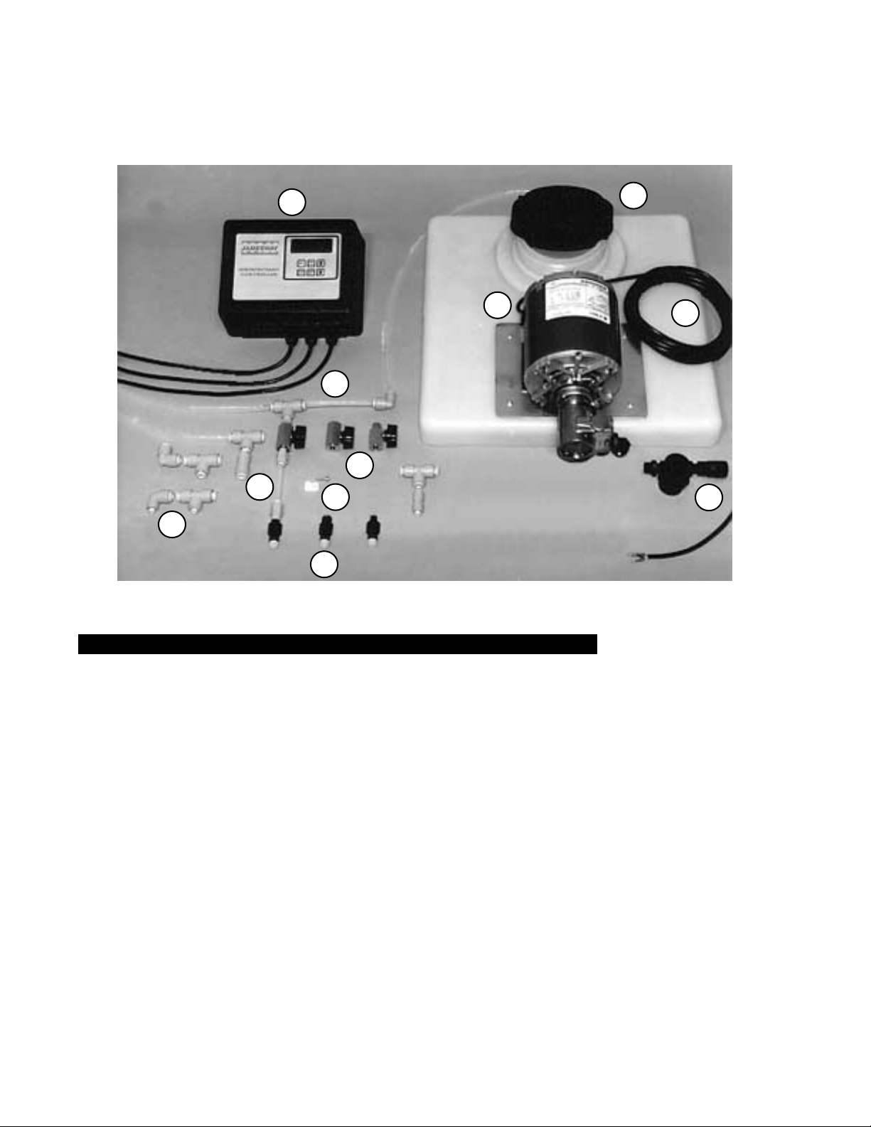
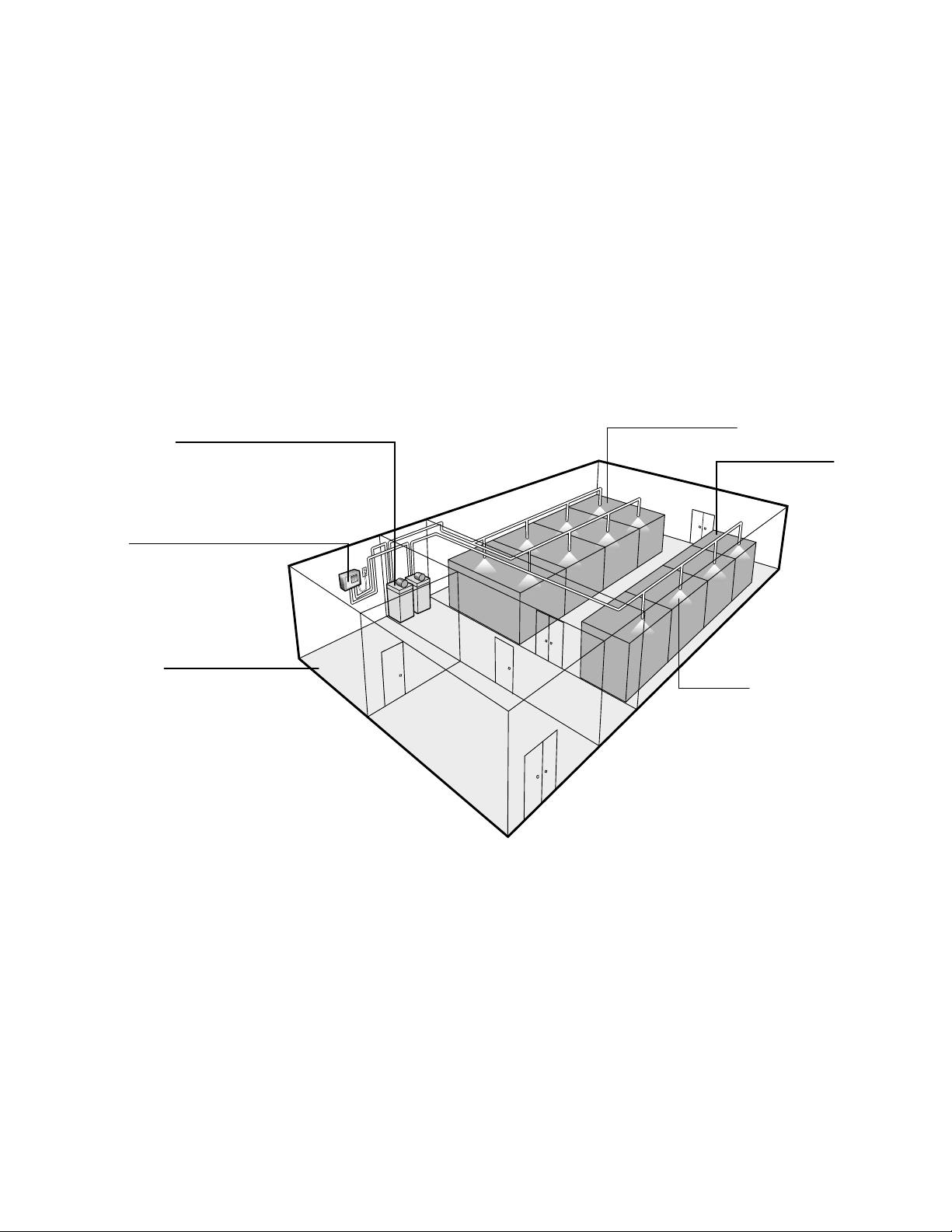
Component Layout............................................................................................................................6
Hatchery Disinfectant System ........................................................................................................6
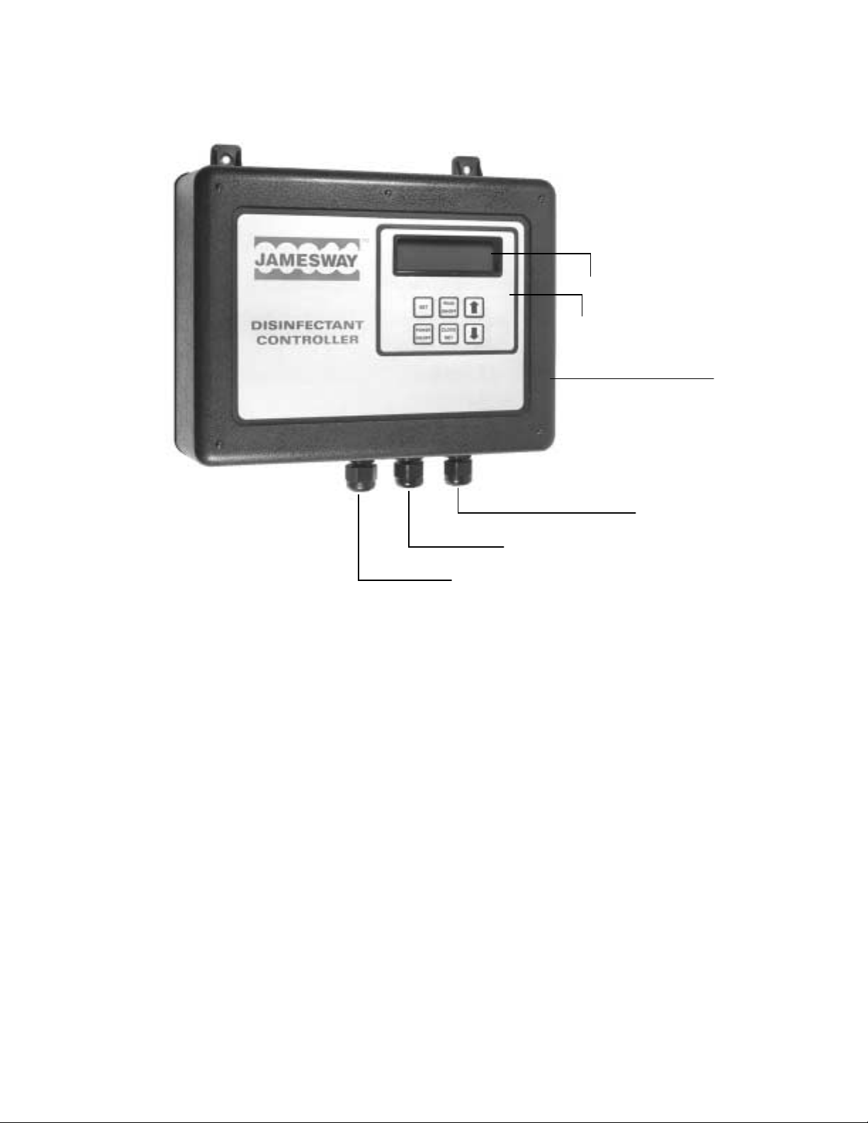
Electronic Controller Features ..........................................................................................................7
Hatchery Sanitation.............................................................................................................................8
General .............................................................................................................................................8
Disinfectants .....................................................................................................................................8
Installation ...........................................................................................................................................9
General .............................................................................................................................................9
Location ..........................................................................................................................................10
Atomizer Units ..............................................................................................................................10
Test Point Locations .....................................................................................................................10
The Electronic Controller and Dilution Tanks................................................................................10
The Voltage Select Switch ..............................................................................................................11
Mounting the Electronic Controller..................................................................................................11
Atomizer Positioning .......................................................................................................................12
Recommendations for Installation ................................................................................................12
Quick Connections .......................................................................................................................12
Installation in Jamesway Incubators and Hatchers.........................................................................13
The Multi-Stage Incubator ............................................................................................................13
The Common Wall Hatcher ..........................................................................................................13
The PX Hatcher............................................................................................................................14
The Single Stage ACI Incubator or Hatcher .................................................................................15
Operation ..........................................................................................................................................16
General ...........................................................................................................................................16
The Electronic Controller ................................................................................................................16
Programming the Electronic Controller...........................................................................................17
Automated Operation ...................................................................................................................17
Programming Functions ...............................................................................................................18
Reviewing the Program ................................................................................................................20
Preventative and Corrective Maintenance ........................................................................................21
General ...........................................................................................................................................21
Filter Inspection and Cleaning ........................................................................................................21
Atomizer (Nozzle) Inspection..........................................................................................................22
Main Feed Line Test........................................................................................................................22
Disinfectant Usage ............................................................................................................................23
General ...........................................................................................................................................23
Properties of Disinfectants..............................................................................................................23
Recommended Spray Intervals ......................................................................................................24
Guidelines.......................................................................................................................................24

4
Hatchery Disinfectant Manual
Appendix A:Troubleshooting.............................................................................................................25
Electronic Controller .......................................................................................................................25
Appendix B: Parts List.......................................................................................................................26
Hatchery Disinfectant System – Atomizer Unit Installation Kit .......................................................28
Appendix C: Organisms and Surface Disinfectants ..........................................................................30
General ...........................................................................................................................................30
Bacterial Organisms .....................................................................................................................30
Viral Organisms............................................................................................................................30
Fungal Organisms ........................................................................................................................30
Protozoal Organisms....................................................................................................................30
Chemicals Used for Disinfecting .....................................................................................................30
General.........................................................................................................................................30
Cresols and Cresylic Acid ............................................................................................................30
Phenols ........................................................................................................................................30
Phenol Coefficient......................................................................................................................31
Iodine............................................................................................................................................31
Chlorine ........................................................................................................................................31
Quaternary Ammonium................................................................................................................31
Glossary............................................................................................................................................32
Abbreviations.....................................................................................................................................32

Hatchery Disinfectant Manual
5
INTRODUCTION
GENERAL
Jamesway's Hatchery DisinfectantSystem incorporates
a programmable controller that regulates the disper-
sion of liquid chemical disinfectants used in hatcheries.
The Electronic Disinfectant Controller has the capac-
ity to program two independent zones for up to 30 days
with automatic repeat cycling of a 2 to 30 day cycle for
each zone. The following specifications highlight the
operations of the controller and the features of the
Hatchery Disinfectant System:
• The Electronic Controller is housed in a fire-re-
tardant and splash-proofABS plastic housing that
has been designed for a wall mount installation.
• Liquid-tightconnectors are usedfor external power
and zone cable connections.
• A high intensity 16 x 2 digit LED display panel
indicates time of day, day of zone cycle, and zone
ON/OFF cycle setting.
• The design of the Electronic Controller’s internal
circuitry protectsthe unitfrom powersurges, brown
outs and power line noise.An internal systems di-
agnostics test is performed each time the unit is
turned on. In the event of a power outage, power
interruption, or when the controller is switched off,
the internal long life lithium battery will retain the
programmed settings.
• For extended periods of operation, a 60 US gallon
(227 L) polyethylene dilution holding tank is used
for each independently functioning zone.
• A non-corrosive diaphragm pump delivering 120
US g/h (2.0/min) at 125 psi (454 L/h (7.6/min) at
8.6 bars) is located on top of the dilution tank, op-
erating only when a programmed signal is received
from the Electronic Controller.
• Each zone can manage up to 50 atomizer units at
1.20 US g/h (4.54 L/h) per atomizer, and dispers-
ing disinfectant throughout the system at 125 psi
(8.6 bars).
• The Hatchery Disinfectant System can be installed
and operated with any brand of incubator or
hatcher.

6
Hatchery Disinfectant Manual
COMPONENT LAYOUT
HATCHERY DISINFECTANT SYSTEM
Item Part No. Part Identification
1....... EC130..............Electronic Programmable Controller (115 V)
......... EC230..............Electronic Programmable Controller (220 V)
2....... PMH100 ...........Dilution Tank, 60 US gal., only tank lid shown
3....... BP710-115.......Non-corrosive Pump (115 V) 120 g/h @ 125 psi
(454 L/h @ 8.6 bars)
......... BP710-220.......Non-corrosive Pump (220 V) 120 g/h @ 125 psi
....................................(454 L/h @ 8.6 bars)
4..................................Zone Control Cable (from pump)
5....... T111.................In-line Filter
6....... HP205-95C ......Atomizers, Anti-Drip Misters
7....... PMH106...........Shut-off Valves
8....... PMH143...........Quick-disconnect Fitting, Tee
......... PMH144 ...........Quick-disconnect Fitting, Elbow
9....... PMH108...........Wall Fasteners, 1/4" (6.4 mm)
......... PMH138 ...........Wall Fasteners, 3/8" (9.5 mm)
10..... T113.................Flexible Tubing, shut-off valve to atomizer, 1/4" (6.4 mm)
11..... PMH200...........Flexible Tubing, main feed line, 3/8" (9.5 mm)
Figure 1: Component Layout – Hatchery Disinfectant System
12
34
5
6
7
8
9
10
11

Hatchery Disinfectant Manual
7
ELECTRONIC CONTROLLER FEATURES
Figure 2: Electronic Controller Features
Protective Housing
(Fire Retardant ABS)
High Intensity LED Panel
Splash Proof Key Pad
Power input Cable
115/220 VAC, 50/60 Hz
Zone 2 Cable
Zone 1 Cable

8
Hatchery Disinfectant Manual
HATCHERY SANITATION
GENERAL
A thorough sanitation program is critical to the main-
tenance of high hatchability and the production of
healthy chicks. The use of disinfectants, as part of a
routine sanitation program, will eliminate many of the
disease producing microorganisms that negatively ef-
fect the chicks through the incubation and hatching
cycles.
The hatchery should be clean. Organic material should
be kept to a minimum to ensure the surface disinfect-
ants will effectively attack and destroy the
microorganisms.
DISINFECTANTS
Asa standard,all disinfectantsused ina hatcheryshould
possess the following characteristics:
•A proven effective germ killing agent.
•Safe and non-toxic to humans and animals.
•Able to penetrate small amounts of organic mate-
rial and crevices.
•Non-corroding and non-staining to hatchery ma-
chines.
•Water soluble.
•Odour free.
•Readily available.
Surface disinfectants exhibit different levels of effec-
tiveness based on the type of microorganism present.
The most common of these organisms can be grouped
into four main categories: bacterial organisms, viral
organisms, fungal organisms and protozoal organisms.
Disinfectants should be acquired based on the applica-
tion and intended use in specific areas of the hatchery,
seeTable 5 (page 24) for a list of disinfectants and their
recommended usage.
Note: Jamesway Incubator Company does not
recommend the use of any particular chemical.
Using this handbook as a guide, ask the manu-
facturers of the disinfectant solutions for recom-
mendations on chemical usage for specific
individual requirements.
Note: For complete descriptions on disinfectants
and types of organisms present in a hatchery, re-
fer to
Appendix C
of this manual.
Caution: If fumigation is used to control bac-
terial contamination in a hatchery,strict guide-
lines (e.g., those set by the United States
Occupational Safety and Health Administra-
tion) are to be observed. The
Commercial
Chicken Production Manual
– 4th Edition, by
Mack O. North and Donald D. Bell (published
by Van Nostrand Reinhold, New York 1990),
details the use of Formalin. It outlines precau-
tions that should be followed by hatchery man-
agers and personnel.

Hatchery Disinfectant Manual
9
INSTALLATION
GENERAL
The Hatchery Disinfectant System has been designed
to adapt to various hatchery layouts, from small speci-
ality hatcheries to large scale poultry producers. The
Electronic Controller can be placed almost anywhere
in the hatchery (e.g. the hatchery manager’s office),
and the dilution tanks can be isolated in a storage and/
or mechanical/electrical room. The atomizer units are
located inside the incubator and hatcher machines, but
Figure 3: Typical Hatchery Layout with Dual Zone Coverage (not to scale)
canalso besituated inanysection ofthe hatchery where
bacterial contamination is considered a problem. Fig-
ure 3 (below) illustrates a typical hatchery layout with
DualZone coverage totheincubator andhatcher rooms.
Additional controllers can be installed to operate more
than two zones (see Figure 4 on page 10 for an exam-
ple of a multiple zone layout).
Dilution tanks set for dual Zone
coverage (storage room location).
Electronic Disinfectant Controller
(convenient access location)
Atomizer
Zone 1 (Incubators)
Zone 2 (Hatchers)
Manager's Office

10
Hatchery Disinfectant Manual
LOCATION
ATOMIZER UNITS
Plan the installation of the Hatchery Disinfectant Sys-
tem by first determining the number of rooms/areas
within the hatchery that will require atomizer units.
Plan to which zone each of the atomizers will be allo-
cated.
Calculate the number of atomizer units per incubator/
hatcher machine and the exact location of the atomiz-
er’s positioning inside the cabinets. Refer to Figures 7
to 10 on pages 13, 14 and 15 for recommendations re-
garding the placement of the atomizer units in
Jamesway machines.
TEST POINT LOCATIONS
Plan for Pressure Test Point locations within the sys-
tem layout (See Figure 4 below and also Figure 15 on
page 22). They should be located at the end of every
main line. Note: If the pump is located some distance away
from the controller, e.g., in another room, you may
consider enclosing the electrical cable in conduit.
THE ELECTRONIC CONTROLLER AND
DILUTION TANKS
Establish the location of the electronic controller and
the dilution tanks. There should be an electrical outlet
in vicinity of the controller.
Ideally, both tanks and controller should be located
close to each other so that the controller plugs directly
into the pump socket without the use of an extension
cord.
If it is necessary to locate the tank several feet away
from the controller, extension cord (USC118) is avail-
able (25 feet/8 metres). See page 26.
Also, wherever possible, dilution tanks should be lo-
cated no more that 100 feet (30.5 metres) from the
atomizer zones.
Zone 1
layout
Zone 2
layout
Zone 3
layout
Receiving
Egg Work Room
Office
Employee
Wash
Mech.
Room
Incubator Room
Hatcher
Room
Poult Room
Transfer
Room
Egg
Storage
Atomizer Units
Test Point
(typical locations)
Dilution Tanks
Electronic Controller
Figure 4: Component Locations using a Multiple Zone Layout (sample, not to scale)

Hatchery Disinfectant Manual
11
Caution: Ensure the unit is unplugged before at-
tempting the Voltage Select procedure outlined
below.
THEVOLTAGE SELECT SWITCH
Check for 115 or 220 volt operation by accessing the
voltage select switch inside the controller housing.
Separate the back cover of the controller housing by
removing the five self-tapping screws.
Set the slide voltage select switch to the required 115
or 220 volt position and replace the back cover.
Figure 5:Voltage Select Switch and Battery Replacement in the Electronic Controller
Electronic Controller Housing
Back Cover
Electronic Time of Day
Board (EC098)
Mounting Tabs
Self-Tapping Screws (quantity 5)
Lithium Battery
Battery Receptacle
Voltage Select Switch (115/220V)
MOUNTING
THE ELECTRONIC CONTROLLER
Mount the unit to a wall using two screws threaded
through the mounting tabs on the top surface of elec-
tronic controller housing and into the wall. If mounting
to a partition wall, locate wall braces and tap into them.
When the controller is mounted, connect the pump
molded cord (male) to the controller molded cord (fe-
male). Plug the controller into the electrical outlet.

12
Hatchery Disinfectant Manual
ATOMIZER POSITIONING
One Electronic Controller can manage up to 50 atom-
izerunits perzone(twozonesper controller).Thepump
on each dilution tank can distribute disinfectant solu-
tion through the system at 125 psi (8.6 bars) per zone.
RECOMMENDATIONS FOR INSTALLATION
The following recommendations should be observed:
•At Test Point locations, install a tee fitting with
one end capped using a test plug fitting. See Fig-
ure 15 on page 22.
•Use the 3/8" (9.5 mm) tubing from the pump to all
main feed tee fittings.
•If possible, avoid placing the atomizers units more
than 10' (3 metres) apart from each other.
•For a 50 unit zone, observe a maximum 500' (150
metres) of 3/8" (9.5 mm) tubing.
•Use the 1/4" (6.4 mm) tubing from the shut-off
valve (off the tee fitting) to the atomizer (misters)
inside the machines (see Figure 7 on page 13).
•All shut-off valves should be positioned outside
of the machines. This allows uninterrupted ma-
chine operation should the disinfectant system
require shut-off of individual atomizer units (see
Figure 7 on page 13).
•Avoid sharp bends in the routing of the 3/8" (9.5
mm) tubing. Minimal use of 90°elbow fittings is
recommended. With the addition of each elbow,
there is a corresponding drop in line pressure.
•Cut the tubing to the required lengths using a util-
ity knife.
•Use the supplied wall fasteners and attach the tub-
ing to safe and secure wall mounting locations. It
is recommended that two fasteners be used at each
shut-off valve location (i.e. on both shut-off valve
connectors to avoid a twisting motion when oper-
ating the shut-off valve).
Figure 6: Quick Connections
QUICK CONNECTIONS
Most of the tee fittings and couplers supplied are of
the quick disconnect variety. Simply insert the tubing
fully into the coupler end and a leak proof seal is cre-
ated. See Figure 6 .
To insert tubing into fitting: Grasp the fitting and push
the tubing fully into the coupler end (white ring).
To remove the tubing from the fitting: Grasp the fitting
and hold the white ring in.Then pull the tubing straight
out.

Hatchery Disinfectant Manual
13
To Dilution Tank
Air Flow
Multi-Stage Incubator
Wall Fasteners
Tee Fitting
3/8" (9.5 mm) Tubing
1/4" (6.4 mm) Tubing
Shut-off Valve - located
outside of the machine
8" (200 mm)
Atomizer Unit
Drilled ceiling panel hole - 5/16"
(8 mm) maximum diameter.
(magnified for clarity)
INSTALLATION IN JAMESWAY
INCUBATORS AND HATCHERS
THE MULTI-STAGE INCUBATOR
The Multi-Stage incubator requires only one (1) at-
omizer.
Locatethe disinfectantatomizer betweenthe two sets
of humidity spray nozzles, offset to the right of the
damper rod. Place it approximately 8" (200 mm)
down from the ceiling line (measuring from the cen-
tre of the atomizer. It should point in the same
direction as the humidity spray nozzles.
Figure 7:Atomizer Placement in the Multi-Stage Incubator
THE COMMON WALL HATCHER
The Common Wall Hatcher requires only one (1) at-
omizer.
Place the atomizer as close to the top humidity nozzle
as possible. It should point directly at the centre of the
fan. The shut off valve should be placed on the roof,
towards the back wall.
Figure 8:Atomizer Placement in the Common Wall Hatcher
Note: Humidity spray nozzles are generally lo-
cated in the air stream.Therefore, placing the at-
omizers in the same vicinity will optimize their
position and evenly disperse the disinfectants.
Rear Wall
Disinfectant
Atomizer
Top Humidity
Spray Nozzle

14
Hatchery Disinfectant Manual
33-1/4'' (845 mm)
Duct
Spray nozzle
Left
Right
38-1/4'' (972 mm)
Front edge
of duct
Rear wall
Spray nozzle
5/8'' (16 mm)
Lateral view
1/2'' (13 mm)
Centre of
spray nozzle
Duct
Front view
THE PX HATCHER
The PX Hatcher requires two (2) nozzles, one on ei-
ther side of the intake duct.
The nozzle on the right of the duct must be located
33.25" (845 mm) down from the roof. The centre of
the nozzle must be 0.50" (13 mm) away from the duct
and 0.625" (16 mm) back (towards the rear of the cabi-
net) from the corner of the duct.
Figure 9: Atomizer Placement in the PX Hatcher
Thenozzle onthe leftof theduct mustbelocated 38.25"
(972 mm) down from the roof. The centre of the noz-
zle must be 0.50" (13 mm) away from the duct and
0.625" (16 mm) back (towards the rear of the cabinet)
from the corner of the duct).

Hatchery Disinfectant Manual
15
To Dilution Tank
Atomizer Unit
Wall Fasteners
Tee Fitting
3/8" (9.5 mm) Tubing
1/4" (6.4 mm) Tubing
Shut-off Valve - located
outside of the machine
2" (50 mm)
Atomizer (mister)
Drilled ceiling panel hole - 5/16"
(8 mm) maximum diameter.
(magnified for clarity)
Single Stage Incubator or Hatcher
Air Flow
THE SINGLE STAGE ACI INCUBATOR OR HATCHER
The Single Stage machine requires only one (1) noz-
zle.
It should be centred above the ECU and directed to-
wards the centre of the fans. The distance from ceiling
line should be approximately 2" (50 mm).
Figure 10: Atomizer Placement in the Single Stage Incubator or Hatcher
Note: Humidity spray nozzles are generally lo-
cated in the air stream.Therefore, placing the at-
omizers in the same vicinity will optimize their
position and evenly disperse the disinfectants.

16
Hatchery Disinfectant Manual
OPERATION
GENERAL
Oncethe atomizers havebeen installed, thecablerout-
ing completed and the dilution tanks filled with
disinfectant solution, the system can be programmed
for automatic operation.
THE ELECTRONIC CONTROLLER
The Controller can be programmed to operate and
control two independent zones. Programming is en-
tered using the keypad on the front panel of the
controller,whichin turn activatesthe menu-baseddis-
play. Refer to Figure 2 on page 7.
The controller has the capacity to program each of
the two zones for up to 30 days, with automatic re-
peat cycling of a 2 to 30 day cycle.
Plug the unit’s electrical cord into a wall outlet (two
or three prong receptacle, as available). Press the
POWER ON/OFF switch on the keypad.
On initial power up, the LED panel will display the
following information:
JAMESWAY
next message: VERSION 1.09
next: DISINFECTANT
CONTROLLER
The controller will then go into operation
if
there is a
program already in memory. The unit will then dis-
play the following:
3:30:15 PM
1 OFF 4 ON
Note: In the event of power failure, outages, in-
terruptionsorwhen switchedoff,the internal clock
and program are retained by the long life lithium
battery cell.This cell is located inside the control-
ler(refertopage 11 forreplacementinstructions).
Note: If an error message appears at start up,
refer to Appendix A for troubleshooting.
Zone 1 is on the
first day of its
program and the
output is OFF
Zone 2 is on the
fourth day of its
program and the
output is ON.

Hatchery Disinfectant Manual
17
PROGRAMMING
THE ELECTRONIC CONTROLLER
AUTOMATED OPERATION
Use the following step-by-step keypad instructions to
program the controller for automated operation.
Press Key
Power on/off
Power on/off
Clock Set
Clock Set
Clock Set
Display
XX:XX:XX AM
Cont ol Off
XX:XX:XX AM
1 OFF 2 OFF
o (1 ON 2 ON)
SET Hou s
XX:XX:00 AM
Set Minutes
XX:XX:00 AM
Function
Controller will turn off output
relays
Controller enters the operation
mode. (If the unit has a stored
program, see Table 2 for pro-
gramming.)
Press the up or down arrow key
to change the hour reading.
Press the up or down arrow key
to change the minute reading.
Notes
Turning the controller ON will
also activate the ON cycle for
both zones.
If the CLOCK SET key is not
pressed at this time, the con-
trollerwillenter operationmode
after a 20 second delay.
Power ON/OFF Functions
Clock Set Functions
Table 1: Programming Power On/Off and Clock Set Functions

18
Hatchery Disinfectant Manual
PROGRAMMING FUNCTIONS
When programming the controller, keep the following
in mind:
•A pause of more than 20 seconds in the program-
ming procedure will automatically initiate the
operation mode of the controller.
Press Key
SET
SET
SET
SET
SET
SET
Display
ENTER PROGRAM?
PRESS YES F NO A
ENTER ZONE
ZONE 1
ENTER START TIME
XX:XX:00 AM
ENTER START TIME
11:XX:00 AM
ENTER STOP TIME
XX:XX:00 AM
ENTER STOP TIME
Function
If the up (YES) arrow is pressed
and the controller enters PRO-
GRAMMING mode. If the down
(NO) arrow is pressed and no
actionistakenwithin10 seconds,
the controller returns to normal
operation.
Presstheup arrowtoreverttothe
other zone (as required).
TheHOUR digitswillflash initially.
Pressthe uparrowtoadvancethe
HOURreadingfrom 1:00to 12:00
a.m. or p.m.
The MINUTES digits will flash ini-
tially.Press the up or down arrow
to advance the MINUTES read-
ing from 00 to 59.
TheHOUR digitswillflash initially.
Pressthe uparrowtoadvancethe
HOURreadingfrom 1:00to 12:00
a.m. or p.m.
The MINUTES digits will flash ini-
tially.Press the up or down arrow
to advance the MINUTES read-
ing from 00 to 59 minutes.
Notes
Use this step to avoid acciden-
tal program changes.
Press SET to lock in Zone.
Thedigits canbe advancedone
at a time by briefly pressing on
the up or down arrow keys.
The SECONDS are not pro-
grammable for the START/
STOP times.
If the STOP time is earlier than
the START time, the program
will START on a given day and
STOP on the following day.The
day shown on the display will
remain as it is past midnight,
and will switch to the next day
after the programmed STOP
time.
Programming Functions
Zone Programming
Start/StopTimes
(continued on the following page)
•If all days are the same, program
one day only
. If
only one zone is to be used, install a simulated pro-
gram in the second zone –this will ensure proper
functioning of the controller.
Table 2: Programming Functions

Hatchery Disinfectant Manual
19
Press Key
SET
SET
SET
SET
YES F
NO A
YES F
NO A
Display
ENTER TIME ON
ON: 0 SECONDS
ENTER TIME OFF
OFF:XXHRXX MIN
ENTER TIME OFF
OFF:XXHRXX MIN
DAY 2 SAME AS DAY 1?
YES F NO A
DAY 3 SAME AS DAY 2?
YES F NO A
END OF PROGRAM?
PRESS YES F NO A
Function
Press the up or down arrow key
to change the SECONDS read-
ing from 000 to 999.
TheHOUR digitswillflash initially.
Press the up or down arrow key
to change the setting.
The MINUTES digits will flash ini-
tially.Press the up or down arrow
to advance the MINUTES read-
ing from 00 to 59.
See next step
As the program steps are re-
peated for subsequent days, the
unit continues to advance to the
next day until the down arrow
(NO) is pressed. See next step.
See next step.
The programming will continue
withthenextdayinthesequence.
e.g. step 4 in this sequence.
Notes
Asthe arrowkeyis pressedand
held, the SECONDS digits will
advance (or back up) slowly at
first and then move at a higher
rate.
To eliminate or skip a day, set
the TIME ON to 0.
Thedigits canbe advancedone
at a time by briefly pressing on
the up or down arrow keys.The
reading can also be advanced
rapidly by pressing and holding
one of the arrow keys (applies
to all settings).
The controller enters into nor-
maloperationandanyprevious
programforthis zoneis erased.
The other zone may be pro-
grammed at this time by
repeating the first PROGRAM-
MING step (above).
Programming can continue for
amaximumof30daysentered.
Programming Functions (continued)
Time ON/Time OFF

20
Hatchery Disinfectant Manual
Press Key
READ ON/OFF
READ ON/OFF
Notes
Pressthe uparrowkeytoac-
celeratethe programreview,
and the down key to move
backward.
The controller will automati-
cally enter the operation
modewhenthe entirereview
program process is com-
plete.
Display
PROGRAM REVIEW
ZONE 1 DAY 01
READ START TIME
8:15:00 AM
READ STOP TIME
3:20:00 PM
READ TIME ON
ON:999 SECONDS
READ TIME OFF
OFF:XXHRXX MIN
PROGRAM REVIEW
ZONE 1 DAY 02
READ START TIME
9:30:00 AM
READ STOP TIME
4:15:00 PM
READ TIME ON
ON:910 SECONDS
READ TIME OFF
OFF:XXHRXX MIN
and so on through
the entire program...
Function
Thisdisplaysteps throughthe
program currently in memory
until the READ ON/OFF key
is pressed again.
Stopsthe reviewprocess.The
controllerenters theoperation
mode once again.
Review Program
REVIEWING THE PROGRAM
Table 3: Review Program
Table of contents
Popular Farm Equipment manuals by other brands

Molon
Molon MINI 120 Use and maintenance manual

Fransgard
Fransgard TI-5000 manual

Cub Cadet
Cub Cadet FastAttach XTREME 19A30039100 installation manual

Krone
Krone Comprima F 125 Original operating instructions

IMV
IMV AlphaVision instruction manual

Redexim
Redexim Verti-Drain 7120 User Manual and Parts Manual

Goldacres
Goldacres MY17-19 Operator's manual

LEMKEN
LEMKEN SIRIUS 12 operating instructions

SILLA
SILLA DUMPER 800 NT SN Operating, maintenance, spare parts manual

Scheppach
Scheppach rs 350 Original instructions

Omlet
Omlet Eglu Cube Wheels instruction manual

Yetter
Yetter SHORT U.N.T. 2967-029B owner's manual