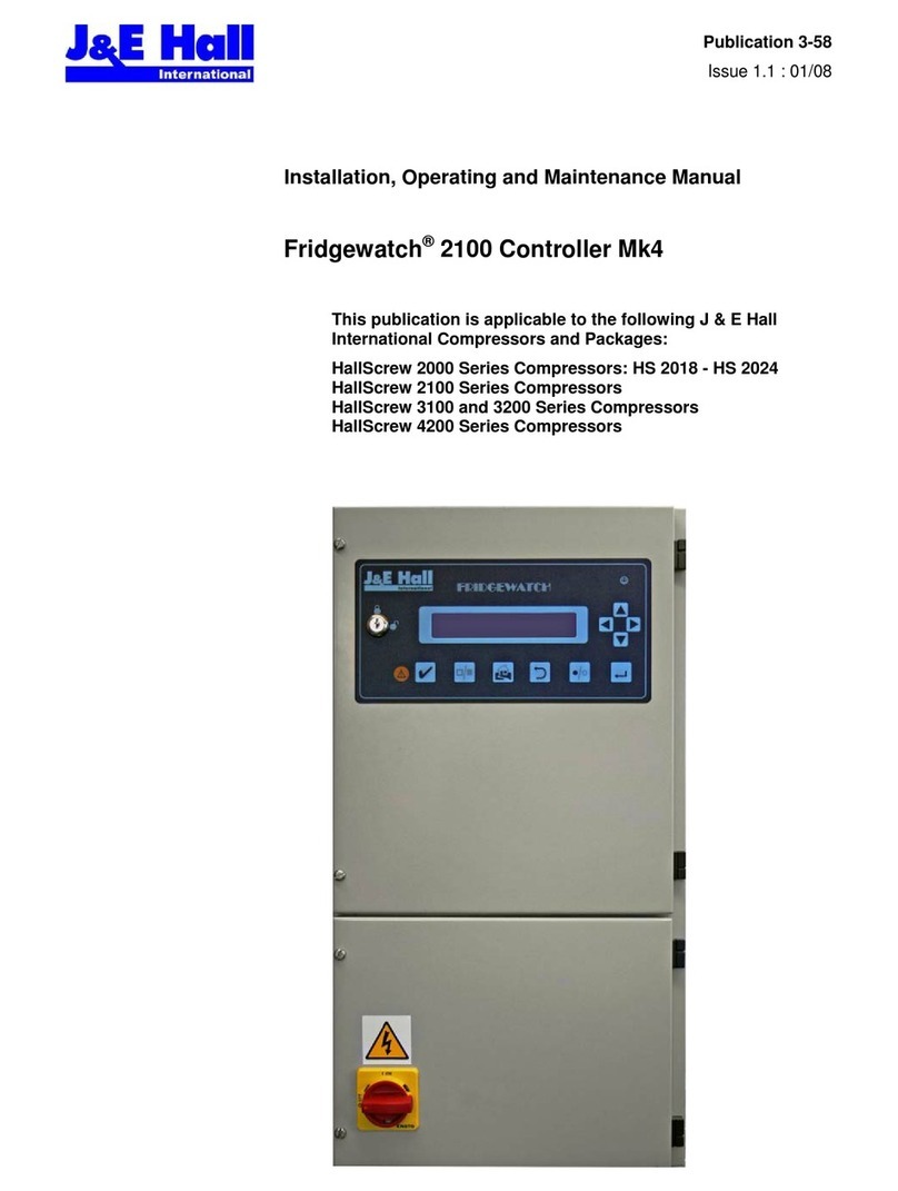
J&E Hall Fridgewatch 4000 Installation guide

Publication 3-71
Issue 3.3 : 01/23
Installation, Operating and Maintenance Manual
Fridgewatch®4000 Controller Mk2
Software Version FW40Mk2P3.105 Onwards
This publication is applicable to the following
J & E Hall International Compressors:
HallScrew HSO 2000, HS 3100, HS 3200,
HS 4200, HS 5200 and HS 6200
Series Compressors

Fridgewatch 4000 Controller Mk2
Publication 3-71 Section 3
Page 2 of 270 Issue 3.3 : 01/23
J & E Hall International©2023
All rights reserved. No part of this publication may be reproduced or transmitted in any form or by
any means, electronic or mechanical, including photocopying, recording or by any information
storage or retrieval system, without permission in writing from the copyright holder.
The copyright in this publication shall be and remain the sole property of J & E Hall International.
FRIDGEWATCHis a registered trade name of J & E Hall International.

Fridgewatch 4000 Controller Mk2
Section 3 Publication 3-71
Issue 3.3 : 01/23 Page 3 of 270
Safety
In common with most other forms of mechanical and electrical
equipment, there are a number of potential hazards associated with
operating and servicing refrigeration plant.
In writing this instruction manual, every emphasis has been given to safe
methods of working. These safety instructions are intended to draw
attention to the potential hazards that could be encountered during
installing, operating and maintaining the plant.
At the same time, it should be emphasised that these notes are not
exhaustive, and are principally intended to draw attention to the most
important points; where necessary, reference is made to other parts of
the manual.
NOTE: The installer is responsible for the correct
installation of equipment, and on completion, the owner
and/or user are responsible for safe operation and
maintenance.
Personnel Permitted to Install, Commission and Maintain the Plant
It is essential that only authorised and competent personnel are allowed
to install, commission and maintain the Fridgewatch Controller. A permit
to work system should be introduced before commissioning begins, and
should be rigorously enforced thereafter.
Any person rendering assistance or under training must be supervised by
the authorised competent person who has responsibility for safety.
Personnel must be familiar with the plant’s
construction, operation and the hazards involved. All
personnel should make a thorough study of these
instructions before undertaking installation,
commissioning, maintenance or repair procedures.

Fridgewatch 4000 Controller Mk2
Publication 3-71 Section 3
Page 4 of 270 Issue 3.3 : 01/23
Electrical
Electrical wiring must be sized and installed to such a standard as to
meet the requirements of the national or local codes pertaining to the
area in which the installation is taking place.
Electrical Isolation
The electrical power used in this equipment is at a voltage high enough to
endanger life.
WARNING
Disconnect the power source before servicing or
repairing electrical equipment.
The only way to be sure
Where there is no local means of isolation or where there is a risk of
reinstatement of the supply, the circuit or equipment to be worked on
must be securely isolated by one of the following methods:
•Isolation using a main switch;
•Distribution board switch (MCB);
•Removal of Cartridge fuses.
Isolation of equipment or circuits using the main switch or distribution
board switch is the preferred method. The point of isolation must be
locked off using a unique key or combination retained by the person
carrying out the work or the appointed person, and a caution notice
attached to the point of isolation.
Where more than one operative is working on circuits supplied from an
isolated distribution board, a multi-lock hasp can be used to prevent
operation of the main isolator until such time that all persons working on
the installation have completed their work and removed their padlocks
from the hasp. If locking-off facilities are not provided on the relevant
switch, then a locked distribution board, which prevents access to the
switch is acceptable provided the key or combination is unique and is
retained by the person doing the work or the appointed person
inadvertent reinstatement of the supply.
Functional Testing
If the supply must remain connected to permit functional testing, fault
diagnosis and repair must only be undertaken by persons who are aware
of the hazard and who have taken adequate precautions to avoid direct
contact with dangerous voltages.
Electrical Hazard in the Event of Fire
If electrical equipment overheats or a fault occurs, it must be
disconnected from the supply and allowed to cool. Overheating may
damage the insulation system, cables, mouldings, gaskets and seals.
The materials used in these components may contain complex organic
compounds, which, when degraded by heat or electrical action, produce
chemical compounds in gaseous, liquid or solid forms. Many of these
gaseous and liquid product compounds are highly flammable and toxic.
If it is necessary to extinguish a fire in electrical equipment, follow the
advice given in the Fire Precautions Act 1971, ‘Guide to Fire Precautions
in Existing Places of Work that require a Fire Certificate’ available from
HMSO. Do not approach the equipment until the fire has been
extinguished and the equipment is cool.
Safe Disposal, End-of-life (EOL)
The controller contains electrical components.At the end of the
controller’s working life, it should not be classed as domestic waste but
be disposed of separately by a registered electrical/electronic waste
recycling company according to local and currently valid legislation.

Fridgewatch 4000 Controller Mk2
Section 3 Publication 3-71
Issue 3.3 : 01/23 Page 5 of 270
Contents
1. About this Publication ................................................................................................. 14
1.1. Safety Warnings and Symbols ...............................................................................................14
1.2. Units of Measurement............................................................................................................14
1.3. Terminology ...........................................................................................................................14
1.4. Additional Copies ...................................................................................................................14
2. Care and Protection of Fridgewatch ........................................................................... 15
2.1. Anti-Static Precautions...........................................................................................................15
2.2. Electrical Interference ............................................................................................................15
2.3. Prolonged Storage .................................................................................................................15
3. Abbreviations .............................................................................................................. 16
4. General Description .................................................................................................... 17
4.1. Standalone Versions..............................................................................................................17
4.1.1. Human-machine Interfaces (HMI) Displays.....................................................................18
4.1.2. Fridgewatch 4000 Controller (Standalone Arrangement) - Mounting ..............................22
4.1.3. Fridgewatch 4000 Controller (Standalone Arrangement) - HMI Interface .......................23
4.2. Integrated Version..................................................................................................................23
5. Application................................................................................................................... 23
5.1. Plant Control and Monitoring .................................................................................................23
5.1.1. Safety Monitoring ............................................................................................................24
5.1.2. Options For Set Point Control .........................................................................................24
5.1.3. Set Point, Start and Stop Values, Second Set Point and Set Point Override ..................24
5.1.4. Operating Modes.............................................................................................................24
5.1.5. Limiting............................................................................................................................25
5.1.6. Oil Management Systems ...............................................................................................25
5.1.7. Auxiliary Control ..............................................................................................................25
6. Principles of Control.................................................................................................... 26
6.1. Compressor Capacity Control ................................................................................................26
6.1.1. HallScrew HSO 2000 Series Capacity Modulation by Slide Valves ................................26
6.1.2. HallScrew HS 3100 to HSO 6200 Series Capacity Modulation by Slide Valves..............26
6.1.3. Slide Valve Position Signal .............................................................................................27
6.2. Intermediate Load Outputs ....................................................................................................27
6.3. Proportional and Integral (P + I) Control ................................................................................29
6.3.1. Proportional Band ...........................................................................................................29
6.3.2. Integral Action Time ........................................................................................................30
6.3.3. Set Point Temperature/Pressure.....................................................................................31
6.3.4. Evaporator Superheat Set Point/Liquid Level Set Point Value ........................................31
6.3.5. Economiser Superheat Set Point ....................................................................................32
6.4. Starting and Stopping the Compressor ..................................................................................32
6.5. Control Philosophy for Compressor Operation After a Transmitter Failure ............................34
6.6. Capacity Control by Fridgewatch 4000 ..................................................................................34
6.6.1. Auto Capacity Control .....................................................................................................34
6.6.2. Remote Capacity Control ................................................................................................34
6.6.3. Manual Capacity Control.................................................................................................35
6.7. Limiting Inputs........................................................................................................................35
6.7.1. Current Limiting...............................................................................................................35
6.7.2. Suction Pressure Limiting ...............................................................................................35
6.7.3. Discharge Pressure Limiting ...........................................................................................35
6.7.4. Evaporator Cooled Medium Outlet Temperature Limiting ...............................................35
6.7.5. Other Limiting Conditions ................................................................................................36
6.7.6. Levels of Limiting ............................................................................................................36
6.8. Discharge High Pressure Trip Switch Function......................................................................36
6.9. Oil Management Systems ......................................................................................................37
6.9.1. Summary of Differential Pressure Sensing .....................................................................38
6.9.2. Demand Oil Pump...........................................................................................................40
6.9.3. Oil Filling Pump ...............................................................................................................41

Fridgewatch 4000 Controller Mk2
Publication 3-71 Section 3
Page 6 of 270 Issue 3.3 : 01/23
7. Fridgewatch System Controller and SCADA .............................................................. 42
7.1. Fridgewatch System Controller ..............................................................................................42
7.2. SCADA System......................................................................................................................42
8. Installation ................................................................................................................... 45
8.1. Digital Inputs and Outputs......................................................................................................45
8.2. Analogue Inputs - Installing Transmitters...............................................................................45
8.2.1. Transmitter Wiring...........................................................................................................46
8.2.2. Transmitter Enabling and Calibration ..............................................................................46
8.3. Using Fridgewatch 4000 to Drive Relays ...............................................................................46
9. Status Indicators ......................................................................................................... 48
10. User Interface.............................................................................................................. 48
10.1. ‘Hard’ and ‘Soft’ Display Function Buttons .............................................................................48
10.2. Interface Common to Every Page ..........................................................................................48
10.2.1. Time and Date.................................................................................................................48
10.2.2. Access Level ...................................................................................................................48
10.2.3. Reset Required Indicator, Acknowledge and Reset Buttons ...........................................49
10.2.4. Current Alarms and Alarm History...................................................................................49
10.2.5. Menu Page......................................................................................................................49
10.2.6. Home Page and DIGINs .................................................................................................50
10.2.7. Back/Next, Analogue Inputs and P + I Diagnostics .........................................................50
11. Home Page ................................................................................................................. 51
11.1. Start (Manual Start/Stop Only) ...............................................................................................53
11.2. Load and Unload (Manual Capacity Control Only).................................................................53
11.3. Controlled Stop/Stop Button RESET......................................................................................53
11.4. System Diagnostics ...............................................................................................................54
12. Menu Page.................................................................................................................. 55
12.1. Read-only Pages ...................................................................................................................56
12.1.1. Digital Inputs ...................................................................................................................56
12.1.2. Digital Outputs.................................................................................................................58
12.1.3. Analogue Inputs ..............................................................................................................60
12.1.4. Analogue Outputs ...........................................................................................................62
12.1.5. P + I Diagnostics .............................................................................................................63
12.1.6. Primary/Secondary..........................................................................................................64
12.1.7. Trending and Logging Data.............................................................................................65
12.1.8. Clean Screen ..................................................................................................................76
12.2. Operator Settings Pages........................................................................................................77
12.2.1. System Control Settings..................................................................................................77
12.2.2. Economiser Control Settings...........................................................................................79
12.2.3. Liquid Injection Control Settings......................................................................................80
12.2.4. Evaporator and Oil Cooler Control Settings ....................................................................81
12.2.5. Condenser Control Settings ............................................................................................82
12.2.6. Hot Gas Valve Control Settings.......................................................................................83
12.2.7. Suction Pressure Limiting Control Settings .....................................................................84
12.2.8. Primary/Secondary Control Settings ...............................................................................85
12.2.9. Alarm, Limiting and Trip Settings, Delay Times...............................................................86
12.2.10. Operating Mode ..............................................................................................................92
12.2.11. Set Time and Date ..........................................................................................................93
12.3. Configuration Settings Pages ................................................................................................94
12.3.1. ANIN Configuration .........................................................................................................94
12.3.2. System Configuration Settings ........................................................................................97
12.3.3. Hours Run and Number of Starts ..................................................................................101
12.3.4. Simulate Outputs...........................................................................................................101
13. Passwords................................................................................................................. 102
13.1. Password Security ...............................................................................................................102
13.2. Entering a Password............................................................................................................103

Fridgewatch 4000 Controller Mk2
Section 3 Publication 3-71
Issue 3.3 : 01/23 Page 7 of 270
14. Commissioning.......................................................................................................... 104
14.1. Supplying Power for the First Time ......................................................................................104
14.2. Commissioning – Sequence of Operations ..........................................................................104
14.2.1. Authority to Use Passwords ..........................................................................................105
14.3. Inputting System Configuration Settings ..............................................................................105
14.3.1. Changing System Configuration Settings after Commissioning ....................................106
14.4. Inputting Operator Settings ..................................................................................................106
14.4.1. Changing Operator Settings after Commissioning ........................................................106
14.5. Operating Mode for the First Start........................................................................................106
15. Display Messages..................................................................................................... 111
15.1. Information Only Messages .................................................................................................111
15.2. Alarm Messages ..................................................................................................................111
15.3. Trip Messages .....................................................................................................................111
15.4. Alarm, Trip and Information Only Messages........................................................................112
15.4.1. Suction Pressure: Alarm, Limiting and Trip ...................................................................112
15.4.2. Suction Temperature High: Trip ....................................................................................112
15.4.3. Suction Superheat: Alarm .............................................................................................112
15.4.4. Discharge Pressure High: Alarm, Limiting and Trip.......................................................113
15.4.5. Discharge Temperature High: Alarm and Trip...............................................................113
15.4.6. Discharge Superheat: Alarm .........................................................................................113
15.4.7. Oil Differential Pressure at Start-up (ODP2) Low: Trip..................................................114
15.4.8. Oil Differential Pressure During Running (ODP1) Low: Alarm and Trip ........................114
15.4.9. Oil Filter Differential Pressure High: Alarm and Trip......................................................115
15.4.10. Oil Injection Temperature High: Alarm and Trip ............................................................115
15.4.11. Lube Oil Temperature High: Alarm and Trip .................................................................115
15.4.12. Oil Separator/Reservoir Level Low: Trip .......................................................................116
15.4.13. Oil Drain Not Clear: Information and Trip ......................................................................116
15.4.14. Compressor Slide Valve Position (Motor Speed) Error: Alarm ......................................116
15.4.15. Compressor Failed to Unload: Trip ...............................................................................116
15.4.16. Condenser Cooling Medium Inlet Temperature: Alarm .................................................117
15.4.17. Condenser Cooling Medium Outlet Temperature: Alarm ..............................................117
15.4.18. Condenser Cooling Medium Differential Pressure Low: Alarm and Trip .......................117
15.4.19. Evaporator Cooled Medium Inlet Temperature: Alarm ..................................................117
15.4.20. Evaporator Cooled Medium Outlet Temperature: Alarm, Limiting and Trip ...................118
15.4.21. Evaporator Cooled Medium Differential Pressure: Alarm and Trip................................118
15.4.22. Evaporator Liquid Level: Alarm and Trip .......................................................................119
15.4.23. Compressor Motor Current: Limiting .............................................................................119
15.4.24. Compressor Motor Temperature High: Trip...................................................................119
15.4.25. Compressor Motor or Starter Failure.............................................................................120
15.4.26. Oil Pump Motor or Starter Failure .................................................................................121
15.4.27. Condenser Pump/Fan Motor or Starter Failure .............................................................122
15.4.28. Evaporator Cooled Medium Pump Motor or Starter Failure ..........................................123
15.4.29. User Trip .......................................................................................................................123
15.4.30. Emergency Stop Pressed .............................................................................................123
15.4.31. Starting or Loading Inhibited .........................................................................................124
15.4.32. Force Unload.................................................................................................................124
15.4.33. External Controller Fault: Evaporator, Economiser, Oil Rectifier or Liquid Injection......125
15.4.1. User Input Faults 1 and 2 (DIGINs I301.4 and I301.5) ..................................................125
15.4.1. Refrigerant Leak Detector .............................................................................................126
15.4.2. Transmitter Out of Range..............................................................................................126
16. External Reset and Alarms, Clearing Alarms and Trips ........................................... 127
16.1. External Alarm/Trip Acknowledge/Reset..............................................................................127
16.2. External Audible and Visual Alarms .....................................................................................127
16.3. Compressor Healthy Signal .................................................................................................127
16.4. Identifying and Clearing Alarms and Trips ...........................................................................127
16.4.1. Normal Healthy Condition .............................................................................................127
16.4.2. Alarm Condition.............................................................................................................128
16.4.3. Acknowledge Alarm ......................................................................................................128
16.4.4. Trip Event......................................................................................................................128

Fridgewatch 4000 Controller Mk2
Publication 3-71 Section 3
Page 8 of 270 Issue 3.3 : 01/23
17. Operator Settings...................................................................................................... 132
17.1. System Control Settings ......................................................................................................132
17.1.1. Set Point, Start and Stop Values...................................................................................133
17.1.2. Stop-to-Start Time Differential.......................................................................................133
17.1.3. Proportional and Integral (P + I) Control........................................................................133
17.1.4. Compressor Unload Limit..............................................................................................134
17.1.5. Load and Unload Pulse Duration ..................................................................................134
17.1.6. Intermediate Load Outputs............................................................................................135
17.1.1. Variable Volume Ratio (VVR) Configuration
For HallScrew 5200 and 6200 Series Compressors .....................................................137
17.2. Economiser Control Settings ...............................................................................................138
17.2.1. Economiser Control Enable and Disable.......................................................................140
17.3. Liquid Injection Control Settings...........................................................................................141
17.4. Evaporator and Oil Cooler Control Settings .........................................................................143
17.4.1. Evaporator Control Settings ..........................................................................................143
17.4.2. Oil Cooler Control Settings............................................................................................145
17.5. Condenser Control Settings .................................................................................................146
17.6. Hot Gas Bypass Valve Control Settings...............................................................................148
17.7. Primary/Secondary Control Settings ....................................................................................150
17.8. Suction Pressure Limiting Control Valve Settings ................................................................151
17.9. Alarm, Limiting and Trip Settings, Delay Times ...................................................................153
17.9.1. Motor Current High........................................................................................................153
17.9.2. Discharge Pressure High ..............................................................................................153
17.9.3. Suction Pressure Low ...................................................................................................154
17.9.4. Suction Pressure High ..................................................................................................155
17.9.5. Oil Differential Pressure Low at Start-up .......................................................................155
17.9.6. Oil Differential Pressure Low During Running ...............................................................156
17.9.7. Oil Filter Differential Pressure High ...............................................................................157
17.9.8. Oil Injection Temperature High......................................................................................157
17.9.9. Lube Oil Temperature High ...........................................................................................158
17.9.10. Discharge Temperature High ........................................................................................158
17.9.11. Suction Temperature High ............................................................................................158
17.9.12. Condenser Cooling Medium Inlet Temperature High or Low.........................................158
17.9.13. Condenser Cooling Medium Outlet Temperature High or Low......................................158
17.9.14. Condenser Cooling Medium Differential Pressure Low.................................................159
17.9.1. Evaporator Cooled Medium Inlet Temperature High or Low .........................................159
17.9.2. Evaporator Liquid Level ................................................................................................160
17.9.3. Evaporator Cooled Medium Outlet Temperature Low ...................................................161
17.9.4. Evaporator Cooled Medium Outlet Temperature High ..................................................162
17.9.5. Evaporator Cooled Medium Differential Pressure High.................................................162
17.9.6. Evaporator Cooled Medium Differential Pressure Low..................................................163
17.9.7. Suction Superheat High ................................................................................................163
17.9.8. Suction Superheat Low .................................................................................................164
17.9.9. Discharge Superheat High ............................................................................................164
17.9.10. Discharge Superheat Low .............................................................................................165
17.9.11. Unload Pulses Per Sample Time ..................................................................................165
17.9.12. Oil Drain Delay Time .....................................................................................................165
17.9.13. User Trip Nuisance Trip Delay Time .............................................................................165
17.9.14. Oil Separator/Reservoir Nuisance Trip Delay Time.......................................................165
18. Configuration Settings............................................................................................... 166
18.1. ANIN Configuration, Calibration and Scaling .......................................................................166
18.1.1. Transmitter Calibration Overview ..................................................................................166
18.1.2. Pressure Transmitter Calibration...................................................................................167
18.1.3. Temperature Transmitter Calibration ............................................................................168
18.1.4. Motor Current Transmitter Calibration ...........................................................................169
18.1.5. Compressor Slide Valve Position LVDT Calibration ......................................................169

Fridgewatch 4000 Controller Mk2
Section 3 Publication 3-71
Issue 3.3 : 01/23 Page 9 of 270
18.2. System Configuration...........................................................................................................170
18.2.1. Compressor Number.....................................................................................................170
18.2.2. System Refrigerant .......................................................................................................170
18.2.3. Compressor Drive .........................................................................................................171
18.2.4. Compressor Number of Starts.......................................................................................171
18.2.5. Oil Management System ...............................................................................................171
18.2.6. Oil Differential Pressure at Start-up...............................................................................171
18.2.7. Oil Differential Pressure During Running ......................................................................172
18.2.8. Oil Filter Differential Pressure .......................................................................................173
18.2.9. Compressor Capacity Control Valve Type ....................................................................174
18.2.10. Compressor Slide Valve Position/Motor Speed Correction ...........................................175
18.2.11. Slide Valve Position/Motor Speed Value For Minimum Load ........................................177
18.2.12. Compressor Fails to Unload at Start .............................................................................177
18.2.13. Control, Start and Stop Variables, Second Set Point ....................................................177
18.2.14. Run Enable Signal ........................................................................................................178
18.2.15. Compressor Start Time .................................................................................................179
18.2.16. Oil Pump Start Time and Minimum Run Time ...............................................................179
18.2.17. Demand Oil Pump Start and Stop .................................................................................179
18.2.18. Evaporator Pump Selection, Start and Run Times........................................................180
18.2.19. Condenser Start Time and Run-on Time ......................................................................180
18.2.20. Pump-down ...................................................................................................................180
18.2.21. Oil Rectifier Enable .......................................................................................................181
18.2.22. Economiser Superheat Control Enable .........................................................................181
18.2.23. Evaporator Superheat or Liquid Level Control Enable ..................................................182
18.2.24. Liquid Injection Control Enable......................................................................................182
18.2.25. Condensing Pressure Control Enable ...........................................................................182
18.2.26. Compressor Slide Valve Position/Motor Speed Definition.............................................183
18.2.27. Operating Mode Indication ............................................................................................183
18.2.28. Communications ...........................................................................................................183
18.2.29. Hot Gas Bypass Valve or Suction Pressure Limiting Control Enable ............................184
18.2.30. HallScrew Compressor Variable Volume Ration (VVR) Enable and Slide Valve Option184
18.2.31. Primary/Secondary........................................................................................................185
18.2.32. Variable Speed Drive ....................................................................................................185
18.2.33. Measurement Units .......................................................................................................185
19. Maintenance.............................................................................................................. 187
19.1. Maintenance Check List.......................................................................................................187
20. Spares....................................................................................................................... 187

Fridgewatch 4000 Controller Mk2
Publication 3-71 Section 3
Page 10 of 270 Issue 3.3 : 01/23
List of Figures
Fig 1 Fridgewatch 4000 Controller (Standalone Versions) – Front Panel and HMI Displays ................18
Fig 2 Fridgewatch 4000 Controller (Standalone Standard Version) – Panel Internal Layout................19
Fig 3 Fridgewatch 4000 Controller (Standalone Standard and Harsh Environment Versions) -
Enclosure .................................................................................................................................21
Fig 4 Fridgewatch 4000 Controller (Standalone Arrangement) - Mounting...........................................22
Fig 5 Proportional and Integral (P + I) Control ......................................................................................28
Fig 6 Integral Control Action .................................................................................................................30
Fig 7 Possible Compressor Start/Stop and Capacity Control Modes....................................................33
Fig 8 Fridgewatch 4000 Controller Interface With Fridgewatch System Controller...............................43
Fig 9 Fridgewatch 4000 Controller Interface With SCADA ...................................................................44
Fig 10 Digital Inputs With Inputs Connected (Page 1 Illustrated)..........................................................45
Fig 11 Connecting Diodes ....................................................................................................................46
Fig 12 Transmitter Installation ..............................................................................................................47
Fig 13 Home Page Example: Compressor in ‘Off’ Mode and SC1 and SC2 Not Configured ...............51
Fig 14 Home Page Example: Compressor ‘Available’ ..........................................................................52
Fig 15 Home Page Example: Compressor ‘Tripped’.............................................................................52
Fig 16 System Diagnostics Page..........................................................................................................54
Fig 17 Menu Page ................................................................................................................................55
Fig 18 Digital Inputs Pages 1 to 3.........................................................................................................56
Fig 19 Digital Outputs Pages 1 to 3 ......................................................................................................58
Fig 20 Analogue Inputs Pages 1 to 4....................................................................................................60
Fig 21 Analogue Outputs Pages 1 and 2..............................................................................................62
Fig 22 P + I Diagnostics Page ..............................................................................................................63
Fig 23 Primary Compressor Page ........................................................................................................64
Fig 24 Secondary Compressor Page....................................................................................................64
Fig 25 Trending and Logging Data Page..............................................................................................65
Fig 26 Trending Data – Evaporator Inlet and Outlet Temperature........................................................65
Fig 27 Trending Data – Condenser Inlet and Outlet Temperature........................................................66
Fig 28 Trending Data – Compressor Discharge, Suction and Oil Temperature....................................66
Fig 29 Trending Data – Compressor Discharge, Suction and Oil Injection Pressure............................67
Fig 30 Trending Data – Compressor Capacity......................................................................................67
Fig 31 Trending Data – Compressor Motor Current .............................................................................68
Fig 32 Trending Data – Compressor Lub Oil and Net Oil Pressure, Oil Filter Differential Pressure .....68
Fig 33 Trending Data – Compressor Discharge and Suction Superheat ..............................................69
Fig 34 Trending Example 1 ..................................................................................................................70
Fig 35 Trending Example 1 ..................................................................................................................70
Fig 36 Connecting to the CPU via Ethernet Cable................................................................................72
Fig 37 Trending and Logging Data – Data Logging ..............................................................................73
Fig 38 Uploading Data Log Files ..........................................................................................................74
Fig 39 Clean Screen.............................................................................................................................76
Fig 40 System Control Settings Pages 1 to 3 .......................................................................................77
Fig 41 Economiser Control Settings Pages 1 and 2 .............................................................................79
Fig 42 Liquid Injection Control Settings Page .......................................................................................80
Fig 43 Evaporator and Oil Cooler Control Settings Pages 1 and 2.......................................................81
Fig 44 Condenser Control Settings Page .............................................................................................82
Fig 45 Hot Gas Valve Control Settings Page........................................................................................83
Fig 46 Suction Pressure Limiting Control Settings Page ......................................................................84
Fig 47 Primary/Secondary Control Settings Page ................................................................................85
Fig 48 Alarm, Limit & Trip Settings Pages 1 to 11 ................................................................................86
Fig 49 Operating Mode Page................................................................................................................92
Fig 50 Set Time and Date Page ...........................................................................................................93

Fridgewatch 4000 Controller Mk2
Section 3 Publication 3-71
Issue 3.3 : 01/23 Page 11 of 270
Fig 51 ANIN Configuration Pages 1 to 4...............................................................................................94
Fig 52 System Configuration Pages 1 to 6 ...........................................................................................97
Fig 53 Hours Run and Number of Starts Page ...................................................................................101
Fig 54 Screen Page Categories and Colour Coding...........................................................................102
Fig 55 Password Logon......................................................................................................................103
Fig 56 Viewing or Changing System Configuration Settings ..............................................................107
Fig 57 Viewing or Changing Control Settings .....................................................................................108
Fig 58 Viewing or Changing Operator Settings...................................................................................109
Fig 59 Identifying and Clearing Alarms and Trips ...............................................................................129
Fig 60 Limiting, Alarm and Alarm History Screens .............................................................................131
Fig 61 Example of Using Intermediate Load Output 1 ........................................................................136
Fig 62 Cycle Time...............................................................................................................................139
Fig 63 Discharge Pressure High: Settings ALT9, ALT10, ALT11, ALT12 and ALTT3 ........................154
Fig 64 Suction Pressure Low: Settings ALT2, ALT3, ALT7, ALT8 and ALTT2 ...................................155
Fig 65 Oil Differential Pressure Low During Running: Settings
ALT14, ALT15, ALTT5, ALTT6 and ALTT27 ..........................................................................157
Fig 66 Condenser Cooling Medium Differential Pressure Low: Settings
ALT43, ALT44, ALTT23, ALTT31 and ALTT33 ......................................................................160
Fig 67 Evaporator Liquid Level: Settings ALT51, ALT52, ALT53, ALTT34 and ALTT35 ....................161
Fig 68 Evaporator Cooled Medium Outlet Temperature Low: Settings
ALT24, ALT25, ALT26, ALT27 and ALTT11 ..........................................................................162
Fig 69 Evaporator Cooled Medium Differential Pressure Low: Settings
ALT33, ALT34, ALTT14, ALTT16 and ALTT32 ......................................................................164
Fig 70 Transmitter Calibration ............................................................................................................166
Fig 71 Transmitter Calibration - Examples .........................................................................................167
Fig 72 Slide Valve Position (SVP)/Motor Speed: Error Tolerance - Values For SC11........................176
Fig 73 Example of FW4000 Display Page in Metric and Imperial Units..............................................186
Fig 74 FW4000 Stand-alone Version Internal Equipment Layout and Terminal Arrangement ...........188
Fig 75 Panel Isolator IQ1 for Incoming 24 V dc 10 Amp Supply .........................................................191
Fig 76 Terminal Nomenclature and Identification ...............................................................................191
Fig 77 Slot 1 CPU on Board DIGINS, Addresses I100.0 to I101.5, ANIN 24 and ANOUT 6 ..............192
Fig 78 Slot 2 CPU on Board DIGINS, Addresses I200.0 to I201.7 .....................................................194
Fig 79 Slot 3 CPU on Board DIGINS, Addresses I300.0 to I301.7 .....................................................196
Fig 80 Slot 1 CPU on Board DIGOUTS, Addresses Q100.0 to Q101.1..............................................198
Fig 81 Slot 2 CPU on Board DIGOUTS, Addresses Q200.0 to Q201.7..............................................200
Fig 82 Slot 3 CPU on Board DIGOUTS, Addresses Q300.0 to Q301.7..............................................202
Fig 83 Slot 4 ANINS 0 to 3, ANOUTS 0 and 1....................................................................................204
Fig 84 Slot 5 ANINS 4 to 7, ANOUTS 2 and 3....................................................................................205
Fig 85 Slot 6 ANINS 8 to 11, ANOUTS 4 and 5..................................................................................206
Fig 86 Slot 7 ANINS 12 to 15..............................................................................................................207
Fig 87 Slot 8 ANINS 16 to 19..............................................................................................................208
Fig 88 Slot 9 ANINS 20 to 23..............................................................................................................209
Fig 89 RS 485 Communication Board ................................................................................................210

Fridgewatch 4000 Controller Mk2
Publication 3-71 Section 3
Page 12 of 270 Issue 3.3 : 01/23
List of Tables
Table 1 Abbreviations...........................................................................................................................16
Table 2 Fridgewatch 4000 Controller (Standalone Versions) – Technical Data ...................................17
Table 3 Analogues, Settings and Delay Times.....................................................................................23
Table 4 Options For Set Point Control..................................................................................................24
Table 5 Set Point, Start and Stop Values, Second Set Point Value and Set Point Override ................25
Table 6 Summary of Limiting Inputs and Associated Settings..............................................................35
Table 7 Summary of Differential Pressure Sensing ..............................................................................37
Table 8 All HallScrew Compressors – Oil Pressure Trips by Differential Pressure Switches ...............38
Table 9 HSO 2000 Series Compressors - Oil Pressure Trips by Transmitters .....................................39
Table 10 HS 3100, HS 3200, HS 4200, HS 5200 and HS 6200 Series Compressors -
Oil Pressure Trips by Transmitters...........................................................................................40
Table 11 ‘Hard’ and ‘Soft’ Display Function Buttons.............................................................................48
Table 12 Suction Pressure: Alarm, Limiting and Trip..........................................................................112
Table 13 Suction Temperature High: Trip...........................................................................................112
Table 14 Suction Superheat: Alarm....................................................................................................112
Table 15 Discharge Pressure High: Alarm, Limiting and Trip .............................................................113
Table 16 Discharge Temperature High: Alarm and Trip .....................................................................113
Table 17 Discharge Superheat: Alarm................................................................................................113
Table 18 Oil Differential Pressure at Start-up (ODP2) Low: Trip ........................................................114
Table 19 Oil Differential Pressure During Running (ODP1) Low: Alarm and Trip ...............................114
Table 20 Oil Filter Differential Pressure High: Alarm and Trip ............................................................115
Table 21 Oil Injection Temperature High: Alarm and Trip...................................................................115
Table 22 Lube Oil Temperature High: Alarm and Trip ........................................................................115
Table 23 Oil Separator/Reservoir Level Low: Trip ..............................................................................116
Table 24 Oil Drain Not Clear: Information and Trip.............................................................................116
Table 25 Compressor Slide Valve Position (Motor Speed) Error: Alarm ............................................116
Table 26 Compressor Failed to Unload: Trip ......................................................................................116
Table 27 Condenser Cooling Medium Inlet Temperature: Alarm........................................................117
Table 28 Condenser Cooling Medium Outlet Temperature: Alarm .....................................................117
Table 29 Condenser Cooling Medium Differential Pressure Low: Alarm and Trip ..............................117
Table 30 Evaporator Cooled Medium Inlet Temperature: Alarm.........................................................117
Table 31 Evaporator Cooled Medium Outlet Temperature: Alarm, Limiting and Trip .........................118
Table 32 Evaporator Cooled Medium Differential Pressure: Alarm and Trip ......................................118
Table 33 Evaporator Liquid Level: Alarm and Trip..............................................................................119
Table 34 Compressor Motor Current: Limiting....................................................................................119
Table 35 Compressor Motor Temperature High: Trip .........................................................................119
Table 36 Compressor Motor or Starter Failure ...................................................................................120
Table 37 Oil Pump Motor or Starter Failure ........................................................................................121
Table 38 Condenser Pump/Fan Motor or Starter Failure....................................................................122
Table 39 Evaporator Cooled Medium Pump Motor or Starter Failure.................................................123
Table 40 User Trip..............................................................................................................................123
Table 41 Emergency Stop Pressed ....................................................................................................123
Table 42 Starting or Loading Inhibited................................................................................................124
Table 43 Force Unload .......................................................................................................................124
Table 44 External Controller Fault: Evaporator, Economiser, Oil Rectifier or Liquid Injection ............125
Table 45 User Input Faults 1 and 2 ....................................................................................................125
Table 46 Refrigerant Leak Detector....................................................................................................126
Table 47 External Alarms DIGOUTs Q201.5 and Q201.6 Behaviour .................................................127
Table 48 Variable Volume Ratio (VVR) Applications, Values For S20 and SC48 ...............................137
Table 49 System Refrigerant Type - Values For SC2.........................................................................170
Table 50 Oil Differential Pressure (ODP2) Sensing Defined - Values For SC7 ..................................172
Table 51 Oil Differential Pressure (Running) ODP1 Sensing Defined - Values For SC8....................172
Table 52 Oil Filter Differential Sensing Defined - Values For SC9......................................................173
Table 53 Capacity Control Valve Application and Operation - Values For SC10................................174
Table 54 Run Enable Required in Different Operating Modes - Values for SC18...............................178

Fridgewatch 4000 Controller Mk2
Section 3 Publication 3-71
Issue 3.3 : 01/23 Page 13 of 270
Table 55 Operating Mode Indication - Values For SC42 ....................................................................183
Table 56 Metric Pressure Transmitter and Temperature Sensor Ranges Used With FW4000 ..........186
Table 57 Maintenance Check List ......................................................................................................187
Table 58 Fuses and Relays, Electronic Modules and HMI .................................................................189
Table 59 Residual Risk Register ........................................................................................................190
Table 60 RS 485 Termination and Bias..............................................................................................210
Table 61 Analogue Input ANIN 00/ANIN 25 Quick-Reference and Calculated Values .......................212
Table 62 Analogue Inputs ANIN 00/ANIN 25 Transmitters .................................................................213
Table 63 Analogue Outputs ANOUT 00/ANOUT 07 ...........................................................................213
Table 64 Digital Inputs I100.0/I301.7 ..................................................................................................214
Table 65 Digital Outputs Q100.0/Q301.7............................................................................................216
Table 66 HMI Trip Display Messages.................................................................................................217
Table 67 HMI Alarm Display Messages..............................................................................................218
Table 68 HMI Limiting Display Messages...........................................................................................219
Table 69 HMI Out of Range Display Messages..................................................................................219
Table 70 HMI Out of Range Display Messages..................................................................................220
Table 71 SCADA Information: ANINS, Calculated Values, ANOUTS Etc...........................................221
Table 72 SCADA Information: ANIN Out of Range Flags...................................................................223
Table 73 SCADA Information: ALT Trip Flags ....................................................................................225
Table 74 SCADA Information: ALT Alarm Flags.................................................................................226
Table 75 SCADA Information: Limiting Flags .....................................................................................227
Table 76 SCADA Information: Alarm Inhibit Flags..............................................................................228
Table 77 SCADA Information: DIGINS ...............................................................................................229
Table 78 SCADA Information: DIGOUTS ...........................................................................................230
Table 79 SCADA Information: Communications.................................................................................231
Table 80 SCADA Information: Data Received....................................................................................231
Table 81 SCADA Information: Data Block 33 @ 4 mA and Data Block 34 @ 20 mA .........................232
Table 82 SCADA Information: Array ‘Elapsed Time Array For HMI Data Block 53’............................233
Table 83 SCADA Information: Array ‘Control Diagnostic Data’...........................................................234
Table 84 System Control Setting Addresses S1/S23 .........................................................................235
Table 85 Economiser Control Setting Addresses EC1/EC14 .............................................................236
Table 86 Evaporator Control Setting Addresses E1/E12 ....................................................................236
Table 87 Condenser Control Setting Addresses C1/C10 ...................................................................237
Table 88 Liquid Injection Control Setting Addresses LI1/LI9 ..............................................................237
Table 89 Hot Gas Bypass Valve Control Setting Addresses HG1/HG8..............................................237
Table 90 Primary/Secondary Control Setting Addresses PS1/PS5 ....................................................238
Table 91 Oil Cooler Control Setting Addresses OC1/OC2 .................................................................238
Table 92 Suction Pressure Limiting Control Valve Setting Addresses SPL1/SPL8 ............................238
Table 93 Alarm, Limiting and Trip Setting Addresses ALT0/ALT53....................................................239
Table 94 Alarm, Limiting and Trip Delay Time Setting Addresses ALTT0/ALTT35 ............................241
Table 95 Analogue Input Configuration Setting Addresses ANIN 00/ANIN 25 ...................................242
Table 96 System Configuration Setting Addresses SC1/SC53 ..........................................................244
Table 97 Compressor Number/Compressor Serial Number Record...................................................246
Appendices
Appendix 1 Residual Risk Register ....................................................................................................190
Appendix 2 Wiring Connections..........................................................................................................191
Appendix 3 Analogue Inputs and Outputs ..........................................................................................212
Appendix 4 Digital Inputs and Outputs ...............................................................................................214
Appendix 5 HMI Display Messages ....................................................................................................217
Appendix 6 SCADA Information .........................................................................................................221
Appendix 7 Control Setting Addresses ...............................................................................................235
Appendix 8 Settings Record ...............................................................................................................246

Fridgewatch 4000 Controller Mk2
Publication 3-71 Section 3
Page 14 of 270 Issue 3.3 : 01/23
1. About this Publication
These instructions have been prepared according to the following
standards:
•BS EN ISO 11442: Technical product documentation.
Document management;
•BS EN ISO 12100: Safety of machinery - General principles
for design - Risk assessment and risk reduction;
•BS EN 62023: Structuring of technical information and
documentation;
•BS EN 82079-1: Preparation of instructions for use.
Structuring, content and presentation. General principles
and detailed requirements.
1.1. Safety Warnings and Symbols
The system of safety warnings and symbols is based on:
•BS EN ISO 7010: Graphical symbols. Safety colours and
safety signs. Registered safety signs;
•BS EN 82079-1: Preparation of instructions for use.
Structuring, content and presentation. General principles
and detailed requirements.
DANGER
This indicates a hazard with a high level of risk, which if
not avoided, will result in death or serious injury if
instructions, including recommended precautions, are
not followed.
WARNING
This indicates a hazard with a medium level of risk,
which if not avoided, will result in death or serious
injury if instructions, including recommended
precautions, are not followed. In addition, there is a
high risk of damage to the component, product or
process.
CAUTION
This indicates a hazard with a low level of risk, which if
not avoided, will result in minor or moderate injury if
instructions, including recommended precautions, are
not followed. In addition, there is a potential risk of
damage to the component, product or process.
NOTE: Draws attention to important additional
information.
1.2. Units of Measurement
Quantities are expressed in SI units or SI derived units; refer to J & E Hall
International Standard JEH-ES-02 Guide to the International System of
Units (SI).
1.3. Terminology
Terminology, abbreviations and acronyms are those currently in use
throughout the refrigeration and air conditioning industry; refer to J & E
Hall International Standard JEH-ES-01 Definition of Terms and Acronyms
Used in the Refrigeration Industry.
1.4. Additional Copies
Obtain additional copies of these instructions from J & E Hall
International; go to www.jehall.com.

Fridgewatch 4000 Controller Mk2
Section 3 Publication 3-71
Issue 3.3 : 01/23 Page 15 of 270
2. Care and Protection of Fridgewatch
CAUTION
If welding is to be carried out in the vicinity of the
Fridgewatch or any other items of plant containing
semi-conductor devices, for example, transistors and
microprocessors, the welding equipment must be
adequately earthed adjacent to the point of weld.
The Fridgewatch or other electronic devices must not be
positioned between the site where the welding is taking
place and the point of earth, or irrevocable damage may
be caused to the electronics, with possible
consequential damage to the plant.
2.1. Anti-Static Precautions
Electrostatic discharge can damage the memory card or the receptacle
on the CPU fitted to Fridgewatch.
Damage to the card or its components can occur as the result of
electrostatic discharge from or through personnel.
To protect the modules and components, precautions against
electrostatic hazards must be taken according to BS EN 61340-5-1.
Note the following:
•Persons handling electronic cards must be earthed, in
accordance with BS EN 61340-5-1, to the earth terminal on
the Fridgewatch or other suitable earthing point;
CAUTION
The earth bonding device, for example, wrist strap and
its application, must conform to BS EN 61340-5-1.
•Never remove or replace a component with the Fridgewatch
power supply turned on.
2.2. Electrical Interference
To avoid problems of electrical interference, all low voltage wiring
(transmitters, data communications and 24 V dc) must be adequately
separated from higher voltage ac wiring (110 V, 230 V, 400 V or higher).
A separation of 150 mm is desirable but not always achievable within
control panels.
Low voltage and higher voltage cables should cross at right-angles.
2.3. Prolonged Storage
If the Fridgewatch, or the plant of which it forms a part, is not to be
installed immediately but held in store, observe the following points:
•The Fridgewatch should preferably be stored indoors, in a
well ventilated, clean, warm and dry environment. If
equipment is stored outside, protection from the elements
must be provided; coverings should be selected and
arranged to reduce the risk of condensation;
•Fridgewatch should not be exposed to ambient temperatures
below -15.0 °C.

Fridgewatch 4000 Controller Mk2
Publication 3-71 Section 3
Page 16 of 270 Issue 3.3 : 01/23
3. Abbreviations
The following abbreviations are used in this manual:
Abbreviation Description Abbreviation Description
∆P Delta P (Differential Pressure) LVDT Linear Variable Displacement Transducer
> Greater Than MOP Maximum Operating Pressure
< Less Than MV Measured Variable
≥Greater Than or Equal to NEMA National Electrical Manufacturers Association (USA)
≤Less Than or Equal to OC Oil Cooler
ALT Alarm, Limiting and Trip ODP Oil Differential Pressure
ALTT Alarm, Limiting and Trip delay Times P + I Proportional + Integral
ANIN ANalogue INput PA Proportional Action
ANOUT ANalogue OUTput PB Proportional Band
COP Coefficient Of Performance PLC Programmable Logic Controller
CPU Central Processing Unit PS Primary/Secondary
DCS Distributed Control System PT Pressure Transmitter, signal in millamps (mA) e.g. 4 to 20 mA
DIGIN DIGital INput RS Recommended Standard serial coms protocol (e.g. RS485)
DIGOUT DIGital OUTput RTU Remote Terminal Unit (e.g. Modbus RTU)
EC Economiser Control SCADA Supervisory Control and Data Acquisition
FW4000 FridgeWatch 4000 Controller SH SuperHeat
FW4100 FridgeWatch 4100 Controller SI International System of Units (SI)
FWDC FridgeWatch Duplex Controller SIS Safety Instrumentation System
FWSC FridgeWatch System Controller SP Set Point
FWSHC FridgeWatch SuperHeat Controller SPL Suction Pressure Limiting
GUI Graphical User Interface ST Sample Time
HG Hot Gas SVP Slide Valve Position
HMI Human-Machine Interface TR Trip
HP High Pressure TT Temperature Transmitter, signal in millamps (mA) e.g. 4 to 20 mA
Int Integer (number which is not a fraction; a whole number) VMS Vibration Monitoring System
IA Integral Action
IAT Integral Action Time
IP Ingress Protection
LI Liquid Injection
LP Low Pressure
Table 1 Abbreviations

Fridgewatch 4000 Controller Mk2
Section 3 Publication 3-71
Issue 3.3 : 01/23 Page 17 of 270
4. General Description
The Fridgewatch 4000 Controller (FW4000) is a compact, Siemens S7
series PLC based, integrated solution for the control and management of
compressor packages and chillers fitted with a screw compressor, fixed
or variable speed drive. Fridgewatch replaces the collection of pressure,
temperature and motor current controllers, timers and relays that might
otherwise be used. In addition to the basic functions of compressor
starting and stopping, safety monitoring and capacity control, FW4000
adds a number of enhancements that permit compressor operation to be
optimised to suit the running conditions. Auxiliary control of compressor
liquid injection cooling or oil cooling, economiser and evaporator
expansion valves and condenser fans (fixed or variable speed drive)
means that separate controllers for these devices can be dispensed with,
resulting in a significant cost saving.
FW4000 electronics can be arranged in two ways. In each case the
functionality, number of analogue and digital inputs and outputs etc.
remains the same:
•Standalone versions: refer to 4.1;
•Integrated version: refer to 4.2.
4.1. Standalone Versions
There are two standalone versions: standard and for harsh environments
(for example, outdoors or marine).
The FW4000 standalone arrangement is illustrated in Figs 1 to 4; refer to
Table 2 for technical data.
Standard and
Harsh
Environments
Versions
Enlosure
Internal layout Refer to Fig 2
Specification, dimensions and cable entry Refer to Fig 3
Mounting Refer to Fig 4
Incoming wiring Use 0.5 mm2cable. Bottom entry only to enclosure.
Relays for
digital outputs
Number off Solid-state: 5 off, mechanical: 14 off single pole
Output 24 V dc
Contact rating 8 A continuous at 250 V ac, 3 A inductive at 250 V ac
Human-machine Interface (HMI) display Refer to Fig 1
Communications interface RS 485 – Modbus RTU or Profinet
DIGIN running signals for compressor, oil pump (if fitted) and auxiliaries 4 mA, 30 V dc maximum
Power supply 24 V dc ±10 % 10 Amp
Real-time clock Super capacitor, maintenance-free
Settings back-up Non-volatile memory
Status indicators On front panel for ‘Control On’ and ‘PLC Healthy’
Temperature
limits
Standard
version
Operating ambient temperature range 0.0 to 40.0 °C
Maximum temperature inside panel 50.0 °C
Harsh
environments
version
Operating ambient temperature range -15.0 to +40.0 °C
Maximum temperature inside panel 50.0 °C
Storage (all versions) -15.0 to +60.0 °C
Harsh
Environments
Version Only
Anti-condensation heater 20 W
Heater thermostat Range 0.0 to 60.0 °C. Set to energises heater if <5.0 °C.
Rain canopy (if required) Refer to Fig 3
Table 2 Fridgewatch 4000 Controller (Standalone Versions) – Technical Data

Fridgewatch 4000 Controller Mk2
Publication 3-71 Section 3
Page 18 of 270 Issue 3.3 : 01/23
4.1.1. Human-machine Interfaces (HMI) Displays
The FW4000 controller incorporates one of two different HMI displays,
usage depends on the environment in which the panel is located: indoors
or in a harsh environment; refer to Fig 1.
The KTP900 HMI display is featured in this manual.
KTP900 HMI Basic PN 2nd Generation TP700 HMI Comfort Outdoor
Standalone version usage Standard Harsh environments
Screen size (diagonal) 228.6 mm (9 in) 177.8 mm (7 in)
Display size Width 198 mm x height 111.7 mm Width 152.4 mm x height 91.4 mm
Touch-screen Yes Yes
IP rating IP65 (NEMA type 4 at the front) IP66 (NEMA type 4 at the front)
Fig 1 Fridgewatch 4000 Controller (Standalone Versions) – Front Panel and HMI Displays
HMI Display (KTP900 Illustrated)
‘PLC HEALTHY’
‘CONTROL ON’

Fridgewatch 4000 Controller Mk2
Section 3 Publication 3-71
Issue 3.3 : 01/23 Page 19 of 270
Fig 2 Fridgewatch 4000 Controller (Standalone Standard Version) – Panel Internal Layout
CPU
Earth Connecting Block
MCB
Trunking For Incoming Cables
Gland Plate For 24 V dc Cable Entry
Digital I/O Modules
Analogue I/O Modules
Analogue Input Modules
Ethernet
Module
Fuses
F1 to F5
Incoming
Isolator IQ1
SSR
Relays
Solid State
Relays
Terminals
SLOT 1 SLOT 2 SLOT 3 SLOT 4 SLOT 5 SLOT 6 SLOT 7 SLOT 8 SLOT 9
Table of contents
Other J&E Hall Controllers manuals


