Eltako Support
2023-08-11 2/7
supports encryption, the security teach-in telegram is usually transmitted together with the data
teach-in, in both steps 3 and 5 this button is used.
1.1.1.3 Factory settings:
1. Set A-CLR (red LED goes blinking)
2. Turn Bto B-max and back three times (LED goes off)
1.1.1.4 Manually enable/disable status feedback messages:
1. Set A-CLR (red LED goes blinking)
2. Turn Bto B-min and back three times (LED goes off)
The status message is also automatically enabled by adding a gateway (EEP A5-38-08).
1.1.2 Communication with the gateway
The switch is controlled via a telegram similar to A5-38-08, command 1:Switching. The switch returns
the state as F6 0x70/0x50 (ON/OFF) if enabled. This communication description also applies to other
switch types (see [1] > CONTENTS OF ELTAKO WIRELESS TELEGRAMS)
It is compatible with A5-38-08, does not support some parameters.
1.1.2.1 Recommended pairing procedure –EO-BAC-IP
There are more ways to setup the connection:
1. Using a channel A5-38-08 for control + receive to another channel as F6-3F-7F
2. Defining a virtual device for control (e.g. D5-00-01, F6-10-00) + receiving to another channel
as F6-3F-7F
3. Using a special interface that is tailored to Eltako switch actuators (A5-3F-00-00D =
combination of A5-38-08 transmitting and F6 receiving on one channel) –see below
Summary of the procedure:
A. Defining a virtual device channel A5-38-08
B. Adding the virtual device to the switch (see 1.1.1.1)
C. Adjusting the channel settings to receive the current status of the switch
Point A:
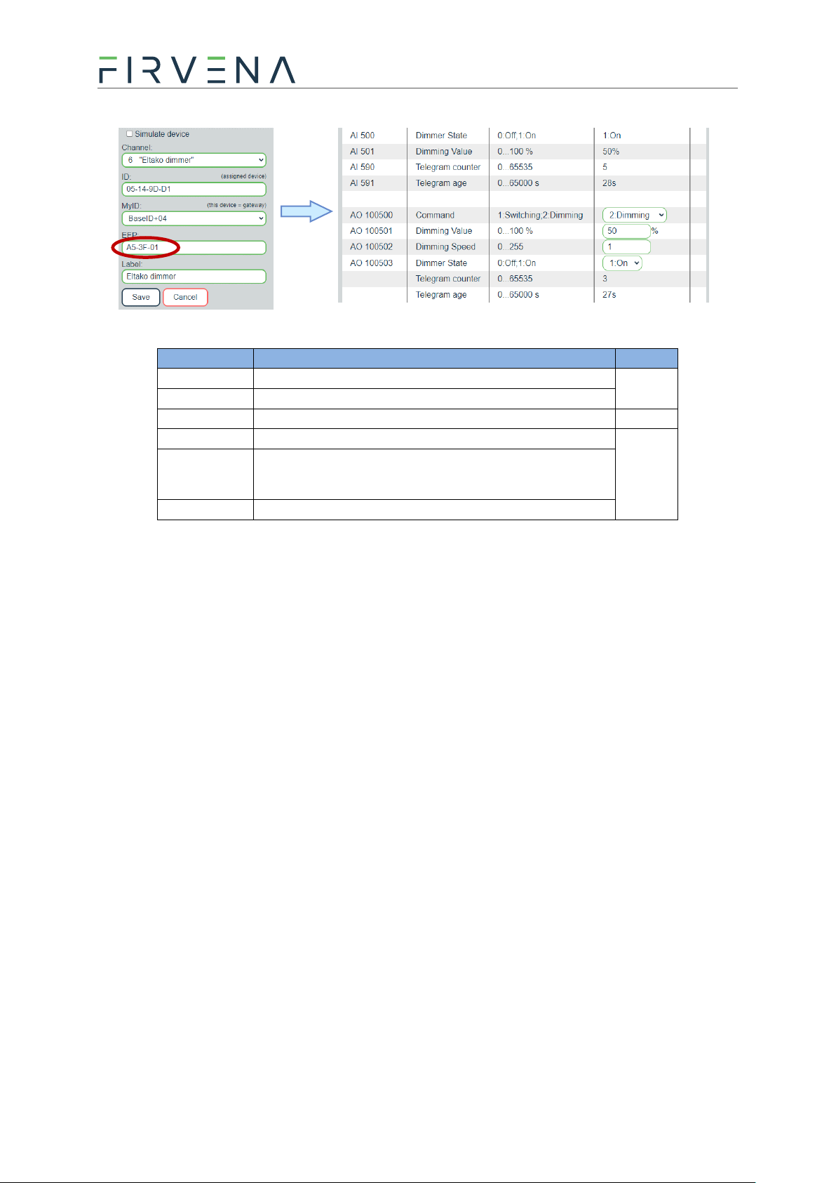
1. Open the Add New > Simulate device box
2. Select a channel
3. Set EEP A5-38-08-00D (0x00D is Manufacturer ID of Eltako)
4. Save