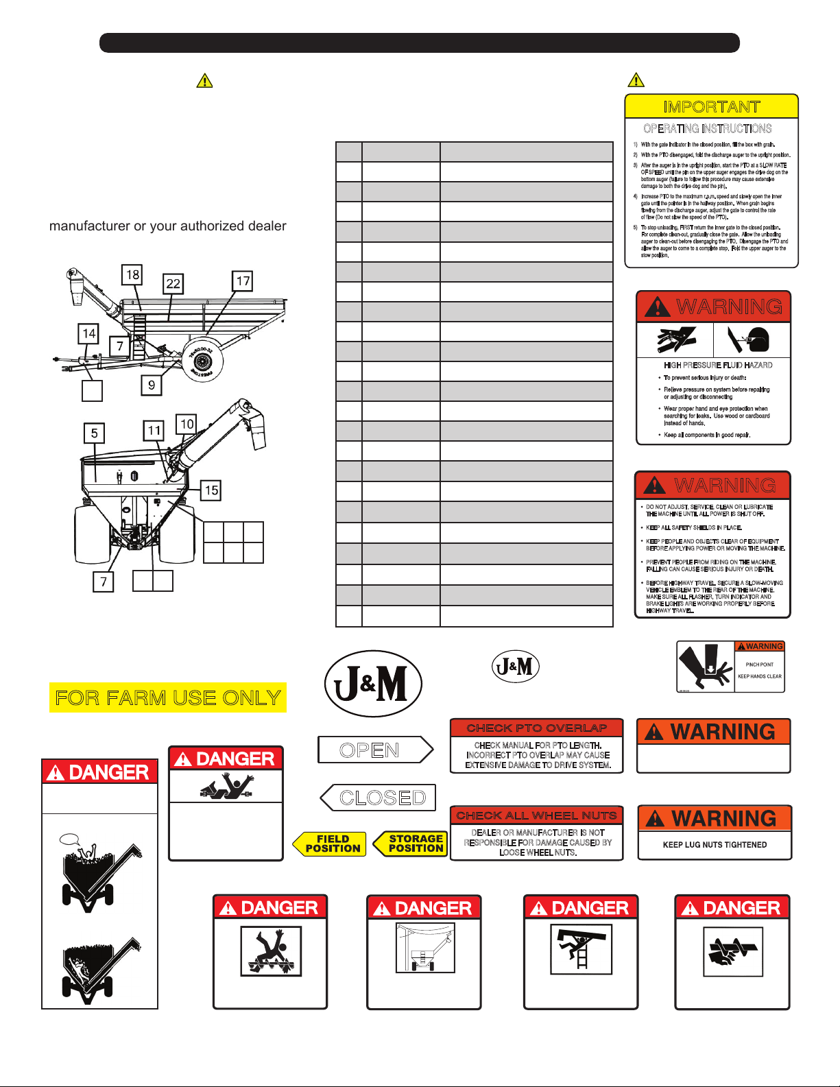
10
Safety Rules
ATTENTION! BECOME ALERT! YOUR SAFETY IS INVOLVED!
Replace Immediately If Damaged or Missing
IMPORTANT: Install new safety signs if
the old signs are destroyed, lost, painted
over or cannot be read. When parts are
replaced that have safety signs, make
sure you install a new sign with each new
part. New signs are available from the
manufacturer or your authorized dealer.
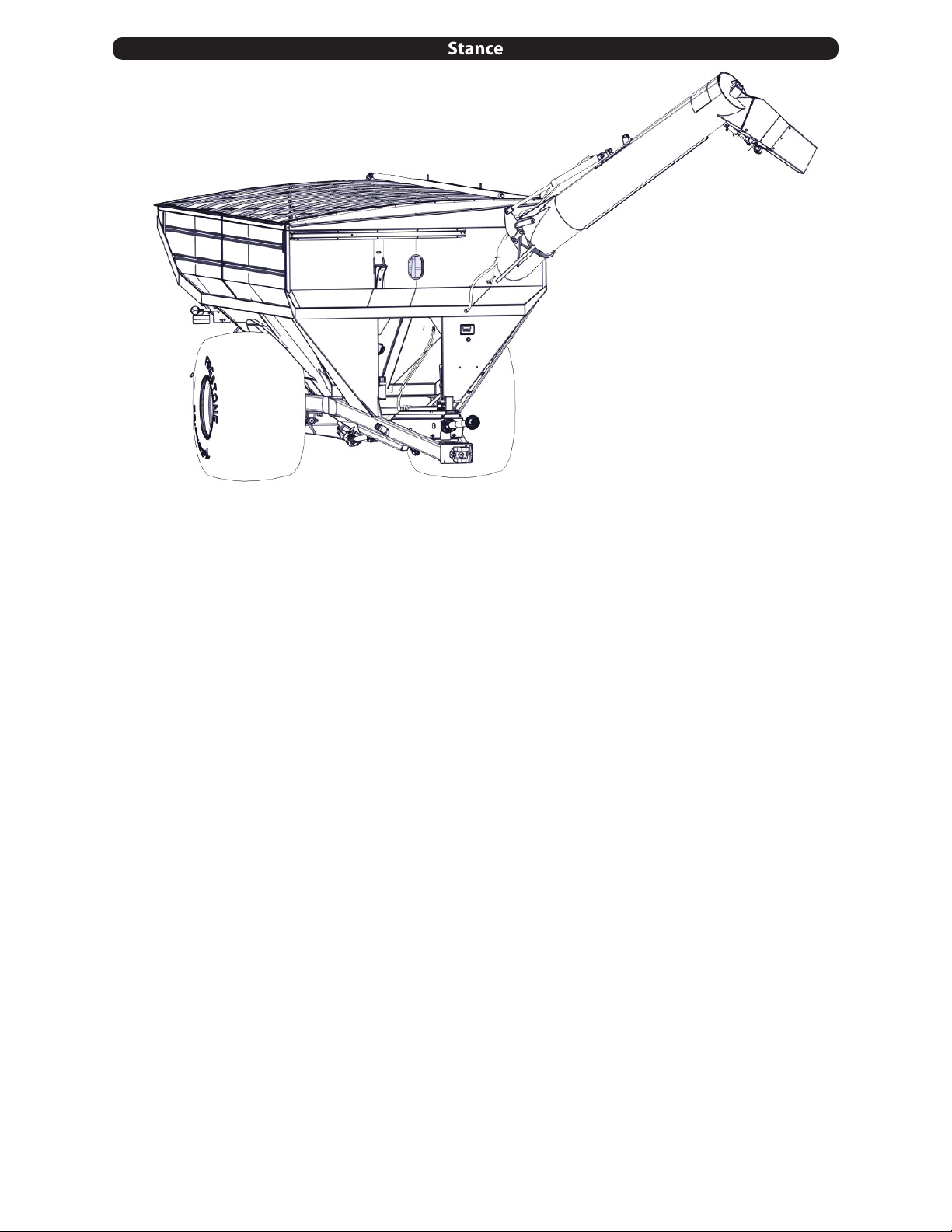
SAFETY DECALS
#1
#2
#3
#16
#17
#4
#8
#9
#21#20#19#18
DO NOT ENTER GRAIN TANK WHEN
AUGER IS RUNNING.
#14
#15
#11
#10
#5
#6
SERIOUS INJURY OR DEATH CAN RESULT
FROM CONTACT WITH ELECTRIC LINES.
USE CARE WHEN MOVING OR OPERATING
THIS MACHINE NEAR ELECTRIC LINES
TO AVOID CONTACT.
KEEP HANDS, FEET, HAIR AND
CLOTHING AWAY FROM MOVING PARTS
ROTATING DRIVELINE
CONTACT CAN CAUSE DEATH.
KEEP AWAY!
• Keep all guards in place when operating.
• Do NOT stand on steps or climb ladder until
all power is shut off.
• Keep hands, feet, hair and clothing away
from moving parts.
#Part # Description
1 JM0018044 Operating Instructions
2 JM0010163 Warning, High Pressure
3 JM0014979 Warning, General
4 JM0018038 Farm Use Only
5 JM0015151 J&M Oval Decal, Large
6 JM0010179 J&M Oval Decal, Medium
7 JM0014994 Warning, Pinch Point
8 JM0018037 Danger, Suocation
9 JM0018036 Danger, Rotating Driveline
10 JM0025433 Open
11 JM0025434 Closed
12 JM0027472 Field Position
13 JM0027473 Storage Position
14 JM0025435 Check PTO Overlap
15 JM0018043 Warning, Check Lug Nuts
16 JM0018039 Warning, Keep Hands Away
17 JM0010150 Warning, Lug Nuts
18 JM0018033 Danger, Do Not Enter Tank
19 JM0015099 Danger, Electric Lines
20 JM0018034 Danger, Keep O Ladder
21 JM0018035 Danger, Keep Hands Away
22 Specify AS Stripe Kit
23 Specify OAS Stripe Kit
#7
#12 #13
19
8 4 2
1 3
12 13
9