manuals.online logo
Brands
  1. Home
  2. •
  3. Brands
  4. •
  5. janitza
  6. •
  7. Measuring Instrument
  8. •
  9. janitza UMG 605US User manual

janitza UMG 605US User manual

Other janitza Measuring Instrument manuals
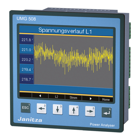
janitza UMG 96 RM-PN User manual

janitza

janitza UMG 96 RM-PN User manual

janitza 800-CT8-LP User manual

janitza

janitza 800-CT8-LP User manual

janitza UMG 96S User manual

janitza

janitza UMG 96S User manual

janitza UMG507 Operating and installation instructions

janitza

janitza UMG507 Operating and installation instructions

janitza UMG 103-CBM Instruction manual

janitza

janitza UMG 103-CBM Instruction manual

janitza UMG 511 User manual

janitza

janitza UMG 511 User manual

janitza UMG 508 User manual

janitza

janitza UMG 508 User manual

janitza UMG 96 RM-EL Instruction manual

janitza

janitza UMG 96 RM-EL Instruction manual

janitza UMG 511 Guide

janitza

janitza UMG 511 Guide

janitza UMG 804 Instruction manual

janitza

janitza UMG 804 Instruction manual

janitza UMG 604-PRO User manual

janitza

janitza UMG 604-PRO User manual
janitza UMG 96-PA Instruction manual

janitza

janitza UMG 96-PA Instruction manual
janitza UMG 804 User manual

janitza

janitza UMG 804 User manual

janitza MRG 512-PRO PQ Flex User manual

janitza

janitza MRG 512-PRO PQ Flex User manual

janitza UMG 500 A User manual

janitza

janitza UMG 500 A User manual

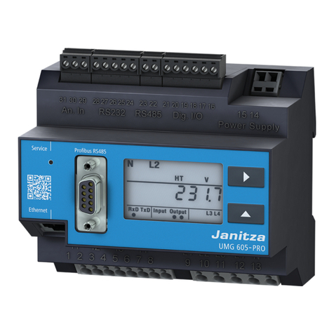
janitza UMG 605-PRO User manual

janitza

janitza UMG 605-PRO User manual

janitza UMG 96-PQ-L-LP User manual

janitza

janitza UMG 96-PQ-L-LP User manual

janitza UMG 103-CBM User manual

janitza

janitza UMG 103-CBM User manual

janitza UMG 96-PQ-L Instruction manual

janitza

janitza UMG 96-PQ-L Instruction manual

janitza UMG 104 Instruction manual

janitza

janitza UMG 104 Instruction manual

janitza UMG 96-PQ-L Instruction manual

janitza

janitza UMG 96-PQ-L Instruction manual

janitza UMG 96RM-P Instruction manual

janitza

janitza UMG 96RM-P Instruction manual

janitza UMG 96S User manual

janitza

janitza UMG 96S User manual

janitza 800-CT8-A User manual

janitza

janitza 800-CT8-A User manual

Popular Measuring Instrument manuals by other brands

Powerfix Profi 278296 Operation and safety notes

Powerfix Profi

Powerfix Profi 278296 Operation and safety notes

Test Equipment Depot GVT-427B user manual

Test Equipment Depot

Test Equipment Depot GVT-427B user manual

Fieldpiece ACH Operator's manual

Fieldpiece

Fieldpiece ACH Operator's manual

FLYSURFER VIRON3 user manual

FLYSURFER

FLYSURFER VIRON3 user manual

GMW TG uni 1 operating manual

GMW

GMW TG uni 1 operating manual

Downeaster Wind & Weather Medallion Series instruction manual

Downeaster

Downeaster Wind & Weather Medallion Series instruction manual

Hanna Instruments HI96725C instruction manual

Hanna Instruments

Hanna Instruments HI96725C instruction manual

Nokeval KMR260 quick guide

Nokeval

Nokeval KMR260 quick guide

HOKUYO AUTOMATIC UBG-05LN instruction manual

HOKUYO AUTOMATIC

HOKUYO AUTOMATIC UBG-05LN instruction manual

Fluke 96000 Series Operator's manual

Fluke

Fluke 96000 Series Operator's manual

Test Products International SP565 user manual

Test Products International

Test Products International SP565 user manual

General Sleep Zmachine Insight+ DT-200 Service manual

General Sleep

General Sleep Zmachine Insight+ DT-200 Service manual

Sensa Core Lacto Spark user manual

Sensa Core

Sensa Core Lacto Spark user manual

VOLTCRAFT UTS-1980 operating instructions

VOLTCRAFT

VOLTCRAFT UTS-1980 operating instructions

EBCHQ 94915 Operation manual

EBCHQ

EBCHQ 94915 Operation manual

Balluff BIP LD2-T017-01-EP-S4 Series user guide

Balluff

Balluff BIP LD2-T017-01-EP-S4 Series user guide

Pulsar IMP Lite Series instruction manual

Pulsar

Pulsar IMP Lite Series instruction manual

ETCR 6800 user manual

ETCR

ETCR 6800 user manual

manuals.online logo
manuals.online logoBrands
  • About & Mission
  • Contact us
  • Privacy Policy
  • Terms and Conditions

Copyright 2025 Manuals.Online. All Rights Reserved.

Doc No. 1.043.002.1.b
Power Quality Analyser
UMG 605US
Operating manual and
technical data
Product No. 33.03.129
Janitza electronics GmbH
Vor dem Polstück 1
D-35633 Lahnau
Support Tel. 0049 6441 9642-22
Fax 0049 6441 9642-30
e-mail: [email protected]
Internet: http://www.janitza.com
www.janitza.com
Profibus
Ethernet
Power supply voltage
Temperature
measurement
input
4 x current
measurement
4 x voltage
measurement
RS232 RS485 2 digital inputs
2 digital outputs
A B
2
UMG 605US
General Information 4
Copyright 4
Protected trademarks 4
Liability disclaimer 4
Comments on the manual 4
Meaning of the symbols used 5
Inspection on receipt 6
Scope of supply 7
Available accessories 7
Notes on Use 8
Product Description 10
Intended use 10
UMG605US features 11
Methods of measurement 12
Operating concept 12
GridVis programming software 13
Three-phase 4-wire systems 14
Three-phase 3-wire systems 16
Use 18
Key functions 18
Concealed key (service) 18
Display mode 19
Programming mode 20
Display password 21
Homepage password 21
Installation 22
Installed position 22
Power supply voltage 23
Current measurement 24
Ammeter 26
Direct measurement 28
Voltage measurement 29
Interfaces 31
RS485 33
RS485 profibus DP V0 slave 35
Digital inputs and outputs 37
Temperature measurement input 41
Putting into Service 42
Applying the power supply voltage 42
Frequency measurement 42
Applying the measuring-circuit voltage 43
Phase sequence 44
Applying the measuring-circuit current 44
Checking the energy measurement 45
Configuration 46
Current transformer ratio 46
Current measurement connection options47
Voltage transformer ratio 48
Voltage measurement connection options49
Interfaces 50
RS232 50
RS485 50
Ethernet 51
Profibus 52
Recordings 55
3
UMG 605US
System information 56
Overrange 56
Serial number 57
Date 57
Firmware release 57
Time 57
Service and maintenance 58
Repair and calibration 58
Front film 58
Battery 58
Firmware update 58
Service 58
Trouble shooting 59
Technical specifications 62
General information 62
Ambient conditions during operation 62
Transport and storage 62
Power supply voltage 63
Protection class 64
Inputs and outputs 65
Temperature measurement input 66
Interfaces 67
Function parameters 68
Specifications for
IEC 61000-4-30 Class S 71
Measuring inputs 72
Parameter list 74
Measured value displays 80
Declaration of conformity 81
Dimensioned drawings 82
UMG605US connection example 83
Quick Reference Instructions 84
4
UMG 605US
General Information
Copyright
This manual is subject to the statutory copy-
right protection provisions and may not be
photocopied, reprinted, reproduced as a
whole or in parts, by mechanical or electronic
means, nor copied or further published in any
other way whatsoever without the legally bind-
ing, written consent of
Janitza electronics GmbH,
Vor dem Polstück 1,
D 35633 Lahnau,
Germany.
Protected trademarks
All trademarks and their resulting rights belong
to the respective holders of these rights.
Liability disclaimer
Janitza electronics GmbH does not accept
any responsibility whatsoever for errors or
deficiencies within this manual and does not
undertake any obligation to keep the content
of this manual up to date.
Comments on the manual
We welcome your comments. If anything in
this manual seems unclear to you, please let
us know by sending an eMail to:
[email protected]
5
UMG 605US
m
c
Meaning of the symbols used
The following pictograms are used in this
manual:
Dangerous voltage!
Danger or risk of severe injury.
Disconnect the system and device
from the power supply before starting
the work.
PE (protective earth) terminal.
Important!
Please note and follow the
documentation. This symbol is
intended to warn you of possi-
ble hazards that can occur during
installation, starting up and use.
6
UMG 605US
m
m
m
Inspection on receipt
Fault free and safe use of this device requires
appropriate transport, proper storage, erection
and assembly as well as careful operation and
maintenance. If it can be assumed that safe
operation is no longer possible, the device
must be immediately taken out of service and
secured against being accidentally started
up.
The device must be unpacked and packed
with the usual care, without the use of force
and only using suitable tools. The devices
must be visually inspected for perfect
mechanical condition. Please also note and
follow the installation instructions enclosed
with the device.
It can be assumed that safe operation is no
longer possible if the device, e.g.
• has visible damage,
• no longer works, despite intact mains power
supply,
• has been exposed to unfavourable conditions
(e.g. storage outside the permissible climatic
limits without adjustment to the ambient
climate, condensation, or similar) for a lengthy
period or was exposed to unfavourable effects
or loads during transport (e.g. fall from a large
height even if there is no visible external
damage, or similar).
Please check the scope of supply for
completeness before you start installing the
device.
All supplied options and design
versions are described on the delivery
note.
The installation and start-up instruc-
tions also describe options which do
not belong to the scope of supply.
All screw-type terminals belonging to
the scope of supply are plugged into
the device.
7
UMG 605US
Product No. Name
21 01 102 Battery, lithium CR2450N, 3 V/540 mAh
08 02 427 RS232, Connection cable (UMG 605US – PC), 2m, 5 poles
1) Refer to delivery note for product number.
2) Design version.
Scope of supply
Number Product No. Name
1 52 16 xxx1) UMG605US XX2)
1 33 03 0xx Installation and start-up instructions
1 33 03 084 Quick guide (supplement to the operating instructions)
1 51 00 116 CD with the following content:
- “GridVis” programming software
- Functional descriptions, GridVis, UMG605US
- GSD file “u605US0c2d.GSD” for profibus DP V0
1 10 01 807 Screw-type terminal, plug-in, 2 pin
1 10 01 808 Screw-type terminal, plug-in, 3 pin
1 10 01 809 Screw-type terminal, plug-in, 5 pin
1 10 01 810 Screw-type terminal, plug-in, 6 pin
1 89 10 051 Slot-head screwdriver (0.40x2 mm), ESD
1 08 01 505 Patch cable, 2m, twisted, grey (UMG605US - PC/switch connection)
1 52 00 008 RS485, external terminating resistor, 120 ohm
Available accessories
8
UMG 605US
Notes on Use
Please read these operating instructions and
all other publications which have to be used
to work with this product (in particular for
installation, operation or maintenance).
Note and follow all safety instructions as well
as any warnings. If you do not follow the
instructions, personal injuries and/or damage
to the product could be the result.
Any unauthorised change or use of this device
which extends beyond the given mechanical,
electrical or other operating limits can cause
personal injuries and/or damage to the
product.
Any such unauthorised change is “misuse”
and/or “negligence” under the product's
warranty and therefore excludes the warranty
for cover of possible resulting injuries or
damage.
This device may be solely operated and
maintained by skilled persons.
Skilled persons are people who, on the basis
of their relevant training and experience, are
capable of identifying risks and avoiding
possible hazards which operation or
maintenance of the device can cause.
When using the device, any additional legal and
safety regulations required for the respective
use must be observed.
9
UMG 605US
m
c
m
Important!
If the device is not operated according
to the instruction manual, protection
is no longer ensured and the device
can cause hazards.
Conductors made of individual wires
must be fitted with wire end ferrules.
Only pluggable screw terminals with
the same number of poles (pins) and
of the same type may be plugged
together.
10
UMG 605US
Product Description
Intended use
The UMG605US is intended to be used for
the measurement and calculation of electrical
variables such as voltage, current, energy,
work, harmonic components, etc. in building
installations, at distribution boards, circuit-
breakers and busbar trunking systems.
Measuring-circuit voltages and currents must
originate from the same system.
The UMG605US is permanently installed in
control cabinets or small distribution boards.
It can be installed in any position.
The measurement results can be displayed,
stored and read out via serial interfaces and
further processed.
The voltage measurement inputs are designed
for measurements in low-voltage systems in
which rated voltages up to 300 V conductor
to earth and surge voltages of overvoltage
category III can occur.
The current measurement inputs of the
UMG605US are connected via external ../1A
or ../5A current transformers.
Mains failure detection
The mains failure detection takes place via the
voltage measurement inputs. The selection of
voltage measurement inputs can be configured
using the GridVis software.
Mains failure stored energy time
The UMG605US bridges the following mains
failures at the auxiliary voltage input:
Mains voltage Stored energy time
230V AC max 80ms
Measurement in medium and high-voltage
systems takes place with current and voltage
transformers. Special safety requirements
must be complied, which are not dealt with in
any greater detail here.
The UMG605US fulfils the test requirements
for use in industrial areas.