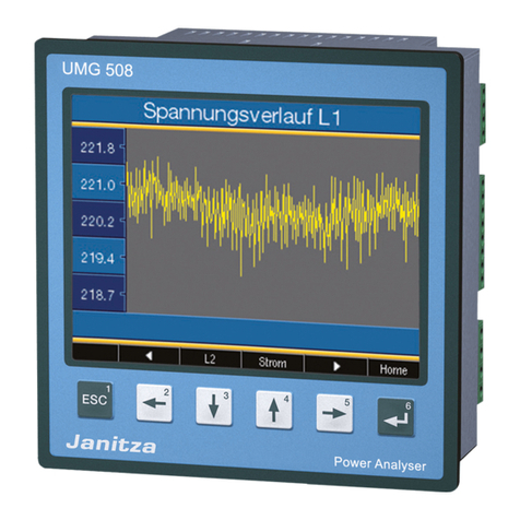
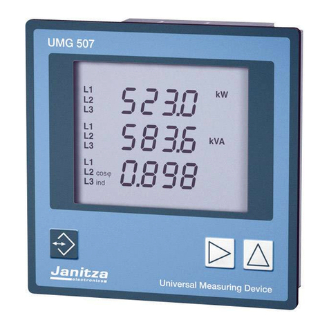
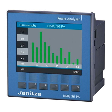
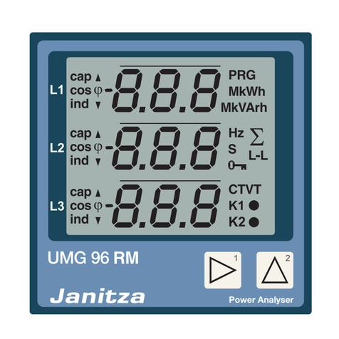
12
4. Product Description
The device is intended for:
• the measurement and calculation of elec-
trical quantities such as voltage, current,
power, energy, harmonics in the building
installation, on distributors, circuit breakers
and busbar distributors.
• the measurement of measuring voltag-
es and currents originating in the same
network.
• measurements in low-voltage networks
in which rating voltages of up to 600 V
conductor to ground and surges of over-
voltage category III may occur.
• Measurement in medium and high-voltage
networks usually does not occur through
current or voltage transformers.
• being built into non-mobile control cab-
inets or small distribution boards. The
position at which it is built in is arbitrary.
• measurement in medium- and high-voltage
networks with current and voltage trans-
formers.
• use in domestic and industrial settings.
• the measurement of current via external
../1 A or ../5 A current transformers.
The measurement results can be displayed
and read out via the device interface for fur-
ther processing.
4. 1 Measurement Procedure
The device:
• continuously measures and calculates all
effective values over a 200 ms interval.
• measures the real effective value (TRMS)
of the voltages and currents connected to
the measurement inputs.
4. 2 Operating Design
You can program the device in many ways
and/or recall measurement values.
• Directly on the device using the 6 keys
and the display.
• Via the programming software GridVis®.
• You can change and open data with the
help of the Modbus address list via the
Modbus protocol. You can find this list at
www.janitza.de.
This user manual only describes the 6-key
operation of the device. The network analysis
software GridVis® has its own "Online Help
Guide."
4. 3 Network Analysis Software
GridVis®
You can program the device and read out the
data with the network analysis software Grid-
Vis® available at www.janitza.de. To do this,
a PC must be connected to the device e.g.
via a serial interface (RS485) or via a gateway
connection.
With the network analysis software GridVis®,
you can:
• program the device.
• configure and read out recordings.
• analyze the data you read out.
• save data in the database.
• display measurement values graphically.
• program client-specific applications.
c
CAUTION!
Malfunction can result
from an improper
connection
If the device is connected improperly, it may
deliver measurement values with errors.
For this reason, please note the follow-
ing:
• Measurement voltages and measure-
ment currents must come from the
same network.
• Do not use the device to measure
direct current.
• Earth the conducting patch boards.