Janome Skyline S5 User manual

SERVICE MANUAL
SKYLINE S5

INDEX
Changing external parts
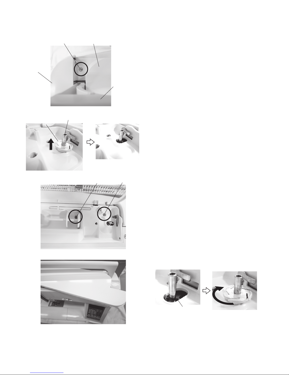
Face cover...........................................................................................................................................1
Belt cover ............................................................................................................................................1
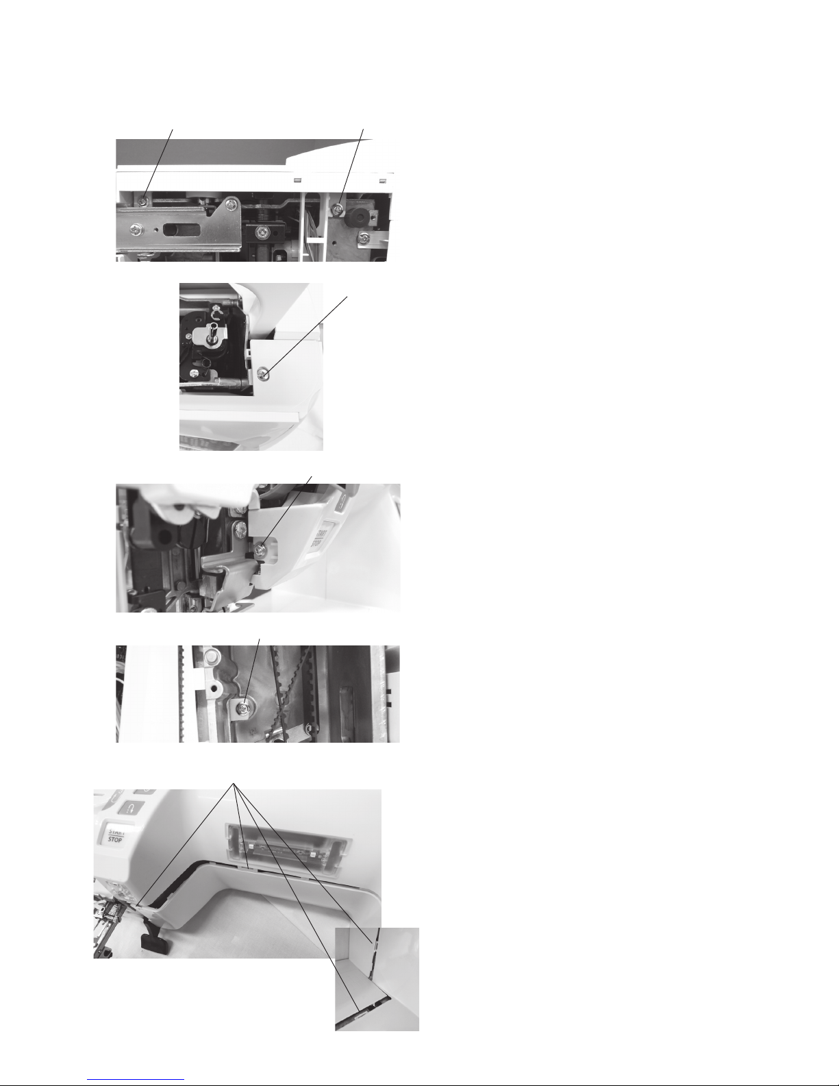
Top cover ............................................................................................................................................2
Machine base......................................................................................................................................3
Base cover ..........................................................................................................................................3
Bed cover ............................................................................................................................................3
Free arm cover....................................................................................................................................4
Front cover ..........................................................................................................................................5
Rear cover...........................................................................................................................................6
Replacing electronic components
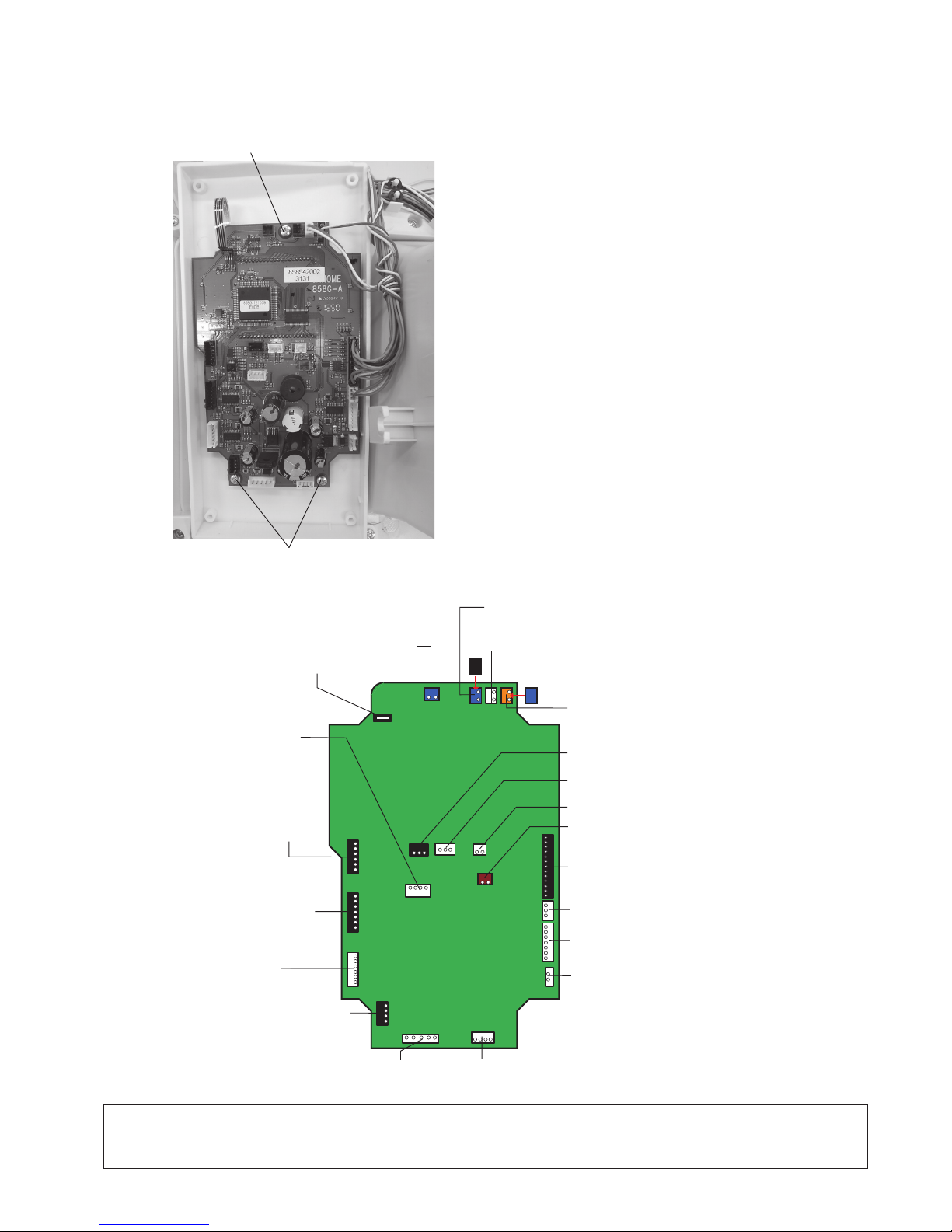
Printed circuit board A.........................................................................................................................7
Printed circuit board F.........................................................................................................................8
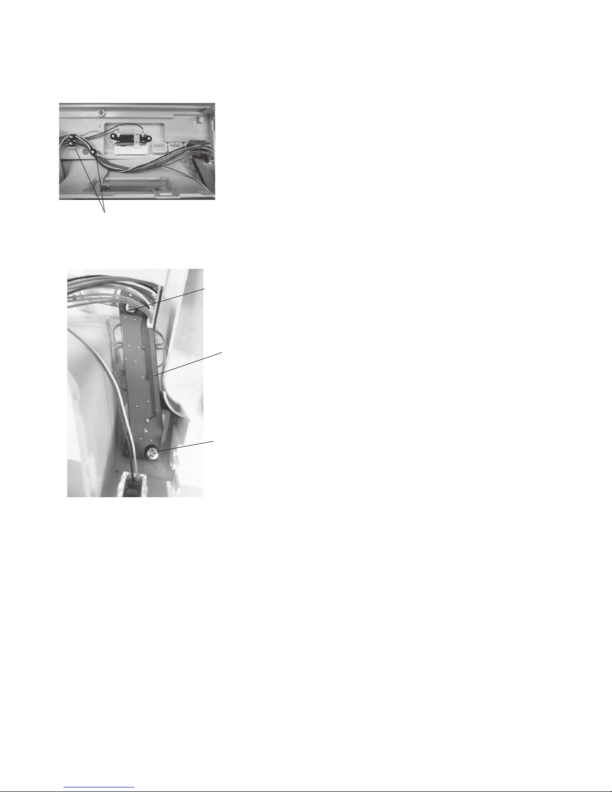
Switching power supply unit................................................................................................................9
DC motor...........................................................................................................................................10
Thread tension unit ...........................................................................................................................11
Mechanical adjustment
Feed dog height ................................................................................................................................12
Needle drop position .........................................................................................................................13
Presser bar height.............................................................................................................................14
Hook timing .......................................................................................................................................15
Needle bar height..............................................................................................................................16
Clearance between needle and tip of the rotary hook ................................................................ 17-18
Presser bar lifter switch position adjustment.....................................................................................19
Backlash between hook drive gear and lower shaft gear..................................................................20
Upper shaft shield plate position.......................................................................................................21
Upper thread tension.........................................................................................................................22
Needle threader plate........................................................................................................................23
Buttonhole lever adjustment..............................................................................................................24
Thread cutter.....................................................................................................................................25
Solenoid position adjustment ............................................................................................................26
Stretch stitch feed balance................................................................................................................27
Needle plate switch ..................................................................................................................... 28-29
Diagnosis test ...................................................................................................................................... 30-36
PARTS LIST .......................................................................................................................................... 37-59

1
Changing external parts
Face cover
To remove:
1. Remove the setscrews A.
Remove the face cover.
To attach:
1. Follow the above procedure in reverse.
Setscrew A
Face cover
Belt cover
To remove:
1. Remove the setscrews A and B.
2. Loosen the setscrew C.
3. Remove the belt cover from the main body.
Be careful not to pull the relay connector.
4. Disconnect the relay connector between the printed
circuit board A and the thread cutter switch socket.
5. Remove the belt cover.
To attach:
1. Follow the above procedure in reverse.
Setscrew A
Setscrew B
Setscrew C
Setscrew C
Belt cover
Relay connector
Cap

2
Changing external parts
Flange plate
Pin
Fig. 2
Top cover
To remove:
1.
Raise the carrying handle and remove the setscrew A.
2. Open the top cover. Pull out the flange plate from the
bobbin winder spindle (see fig. 2).
3. Remove the setscrews B and C.
4. Open the face cover. Close the top cover.
Raise the carrying handle.
Pull the top cover toward you to remove it (see fig. 4).
To attach:
1. Follow the above procedure in reverse.
To attach the flange plate, put the flange plate into the
bobbin winder, and push the flange plate down.
Turn the flange plate until it snaps to the pin of the
bobbin winder spindle (see fig 5).
Setscrew A
Carrying
handle
Top cover
Face cover
Bobbin winder
Fig. 1
Fig. 3
Fig. 4
Fig. 5
Setscrew B Setscrew C

3
Changing external parts
Machine base
To remove:
1. Remove the setscrews A.
2. Remove the machne base.
To attach:
1. Follow the above procedure in reverse.
Setscrew A
Setscrew A
Setscrew A
Setscrew A
Machine base
Base cover
To remove:
1. Remove the setscrews B.
2. Remove the base cover.
To attach:
1. Follow the above procedure in reverse.
Setscrew B
Setscrew B
Setscrew B
Setscrew B
Base cover
Setscrew C
Setscrew C Bed cover Bed cover
To remove:
1. Remove the setscrews C.
2. Remove the bed cover.
To attach:
1. Follow the above procedure in reverse.

4
Free arm cover
To remove:
1. Remove the machine base and base cover (see page 3).
Press the needle plate release lever to remove the
needle plate.
Needle plate release lever
Needle plate
Changing external parts
2. Remove the pin.
Loosen the setscrew.
3. Unlock the hook A (inside of the machine base) and B
(edge of the free arm).
4. Slide the free arm cover to the left.
Remove the free arm cover while removing the 3
hooks and 2 tabs from the free arm.
To attach:
1. Follow the above procedure in reverse.
Pin Free arm cover
Hook A
Hook B
Setscrew
Free arm cover Tabs
Hooks

5
Changing external parts
Setscrew A Setscrew A Front cover
To remove:
1. Remove the top cover, belt cover, base cover, machine
base and free arm cover (see pages 1-4).
2. Loosen the setscrews A (inside of the machine base).
Setscrew B
Setscrew C
Setscrew D
3. Remove the setscrew B.
4. Loosen the setscrew C (inside of the face cover).
5. Loosen the setscrew D (inside of the belt cover).
6. Unlock the hooks from the front cover.
Remove the connectors from the circuit board A.
Remove the front cover.
To attach:
1. Follow the above procedure in reverse.
Refer to page 7 for locating connector posts.
Hooks

6
Changing external parts
Fig. 1 Rear cover Setscrew A
Setscrew B
Fig. 2 Setscrews C
Rear cover
To remove:
1. Lower the presser foot.
2. Remove the belt cover, top cover and base cover (see
pages 1, 2 and 3).
3. Loosen the setscrews A and B (see fig. 1).
Remove the setscrews C (see fig. 2)
4. Push the rear cover from the holes D and E with a
screwdriver to remove the hook of rear cover.
5. Remove the rear cover.
To attach:
1. Follow the above procedure in reverse.
Rear cover
Fig. 3 Hole D
Fig. 4
Hole E

7
Slide volume
Printed circuit board L1
(Underside of the arm)
Printed circuit board A connection
Replacing electronic components
Printed circuit board A
NOTE:
Do not disconnect the connectors by pulling on cord.
To disconnect the connectors, grasp the connector, not
the cord.
To remove:
1. Remove the front cover.
2. Grasp the connector directly with your fingers and pull.
Do not pull the lead wire, as this may damage the
contact sleeve inside of the connector.
Remove the setscrews and printed circuit board A.
To attach:
1. Follow the above procedure in reverse.
Be sure that the connector post on the printed circuit
board to which it is connected.
Position the connector correctly, then push it straight
down until it locks in place.
Printed circuit board L2 (Underside of the function buttons)
* Plug the black connector
Touch panel
Bobbin winder switch
Presser foot
lifter support lift
Printed circuit board L2 (Face cover lamp)
*Plug the blue connector
BH sensor
Feed motor
Thread cutter
motor Solenoid 1
Thread tension
release
Phase sensor
Printed circuit
board F
Zigzag steping motor
DC motor
Program
Needle plate sensor switch
Drop feed switch
Foot control
Power switch
Setscrew
Setscrews
NOTE:
The colors of the connector posts for printed circuit board L2 do not match with the colors of the connectors to be
inserted. Be careful when you insert the connectors into the connector posts.

8
Setscrew
CS rings
Printed circuit board F
To remove:
1. Remove the front cover (see page 5).
2. Disconnect the connector from the printed circuit
board A (see page 7).
3. Remove the CS rings.
4. Remove the setscrews, and the printed circuit board F.
To attach:
1. Follow the above procedure in reverse.
Replacing electronic components
Printed circuit
board F
Setscrew

9
Switching power supply unit
To remove:
1. Remove the belt cover, the top cover and the front
cover (see pages 1, 2 and 5).
2. Loosen the setscrew A. Remove the cord guide plate.
(see fig. 1)
3. Disconnect the switching power supply connector from
the switching power supply unit.(see fig. 2)
4. Remove the foot control connector from the printed
circuit board A.(see fig. 2)(see page 7)
5. Remove the setscrews B, and switching power supply.
(see fig. 2)
To attach:
1. Follow the above procedure in reverse.
Replacing electronic components
Switching power supply connector
Setscrew A
Setscrews B
Foot control
connector (cord)
Cord guide
plate
Setscrew B
Switching power supply unit
Fig. 1
Fig. 2

10
200 g pressure
5 mm
Setscrews
Setscrews
DC motor
To remove:
1. Remove the belt cover, the top cover and the front
cover (see pages 1, 2 and 5).
2. Disconnect the DC motor connector from the printed
circuit board A (see page 7).
3. Remove the motor belt.
4. Remove the setscrews (2 pcs), and the driving motor.
Replacing electronic components
To attach:
1. Attach the driving motor. Tighten the setscrews
temporarily.
2. Adjust the motor belt deflection to about 5 mm by
pressing the middle of the motor belt with your finger
with approximately 200 grams of pressure.
3. Tighten the setscrews securely.
4. Plug the DC motor connector to the printed circuit
board A (see page 7).
5. Attach the front cover, the top cover and the belt cover.
Motor belt

11
Replacing electronic components
Thread tension unit
To remove:
1. Remove the top cover and the front cover (see pages
1 and 5).
2. Disconnect the solenoid 1 thread tension release
connector from the printed circuit board A (see page 7).
3. Remove the spring on the thread tension release lever
(see fig. 1).
3. Insert the screwdriver from the left side of the machine.
Remove the setscrews A and B.
Remove the thread tension unit.
To attach:
1. Follow the above procedure in reverse.
2. Check the upper thread tension (see page 22).
Setscrew B
Setscrew A
Setscrew B
Thread tension
release lever
Fig. 1
Fig. 2
Spring
Thread tension unit

12
Mechanical adjustment
Nut
Setscrew A Adjusting screw B
Presser foot
0.80 – 0.90 mm
Surface of
needle plate
Feed dog
Hexagonal socket screw I
Setscrew D
Threaded hole C
Feed dog height
When the foot pressure dial is at “7” and the presser foot A is lowered, the highest position of the feed dog should be 0.80
to 0.90 mm from the surface of the needle plate.
Adjusting screw B Threaded hole C
Setscrew A
Setscrew D
Adjustment 1:
1. Turn the power switch on. Adjust the stitch length at
maximum length.
Turn the power switch off.
2. Remove the bed cover and base cover.
3. Set the pressure adjusting dial at “7” with the presser
foot lowered.
4. Turn the handwheel toward you to raise the feed dog
at its highest position.
5. Loosen the setscrew A.
6. Loosen the nut.
Adjust the feed dog height to 0.85 mm by turning the
adjusting screw B.
7. Tighten the nut and setscrew A.
8. Attach the bed cover.
Adjustment 2:
If the feed dog is not parallel to the surface of the needle
plate at its highest position, make the adjustment as
follows:
* For this adjustment, a hexagonal socket screw I 4x6,
part no. 000111108 is required.
1. Insert a hexagonal socket screw I, part no. 000111108
into the threaded hole (C) until it stops.
2. Turn the setscrew D clockwise to loosen it.
3. Turn the hexagonal socket screw I until the feed dog
is parallel with the surface of the needle plate.
4. Tighten the setscrew D.
5. Remove the hexagonal socket screw I.
6. Attach the bed cover and base cover.

13
To adjust:
1. Attach the needle #14.
2. Turn the power switch ON. Select straight stitch.
Check that the needle drop position is centered
when the drop position is set at "4.5", and the
clearance between the side of the needle and the
needle hole is 0.2 mm or more when the needle
position is set at "0.0" and "9.0" (see fig. 1).
If this is not the case, adjust as follows;
3. Lower the needle threader until the hexagonal socket
screw shows up (see fig. 3).
Loosen the hexagonal socket screw. Turn the
eccentric pin to adjust the needle drop position.
The direction of eccentric pin should be as shown as
fig. 2.
4. Tighten the hexagonal socket screw.
Check the hook timing and the needle bar height after
this adjustment (see page 17 and 18).
Mechanical adjustment
Needle drop position
When the straight stitch is selected, the needle should be positioned in the center of the needle plate hole.
When the needle drop position is set at "0.0" and "9.0", the clearance between the side of the needle and the needle
hole should be 0.2 mm or more.
Eccentric pin
Needle hole
0.2 mm or more0.2 mm or more
A = B
Hexagonal
socket screw
Eccentric pin
Needle threader
Needle threader
“9.0”
“0.0”
Needle drop position "4.5"
Fig. 1
Fig. 2
Fig. 3

14
Should be
pararell
Mechanical adjustment
Presser bar height
The clearance between the presser foot and the surface of the needle plate should be 6 mm when the presser foot is
raised.
The presser foot (zigzag foot A) should be pararell to the slot of the feed dog teeth when attached.
Zigzag foot A
6 mm
Zigzag foot (A)
Slot
Setscrew
To adjust:
1. Attach the zigzag foot (A).
2. Drop the feed dogs.
3. Raise the presser foot with the presser foot lifter.
4. Open the face cover.
Loosen the setscrew on the presser bar suporter to
adjust the presser foot direction as illustrated so
the slot for the feed dog teeth and the zigzag foot
should be pararell.
5. Place the 6 mm spacer (block) between the presser
foot and the needle plate. Tighten the setscrew while
depressing the foot against the spacer.
Needle plate
Presser foot bar supporter

15
Mechanical adjustment
Setscrew C
Setscrew B
Setscrew A
Hook base plate
Adjustment 1
1. Remove the bed cover (see page 3).
2. Turn the power switch ON, and select the zigzag stitch
pattern 11.
Adjust the stitch width at its maximum (9.0).
3. Remove the presser foot, needle plate and bobbin
holder.
4. Loosen the setscrews A and B.
Loosen the setscrew C just enough to move the hook
base plate.
5. Turn the handwheel toward you.
Adjust the clearance between the needle and the tip
of the rotary hook by moving the hook base plate up
or down between -0.1and +0.05 mm at the both left
and right needle position.
6. Tighten the setscrews A, B and C.
7. Check the backlash between the lower shaft gear and
the hook drive gear. If the backlash is too great or the
engagement of the gears is too tight, adjust the
backlash (see page 20).
* Check the hook timing and needle bar height
after this adjustment (see page 17 and 18)
Clearance between needle and tip of the rotary hook
The clearance between the needle and the point of hook should be -0.1 to +0.05 mm.

16
Mechanical adjustment
Master needle
Tip of hook
-0.1 to +0.05 mm
Master needle
Left needle position Right needle position
1. Remove the top cover (see page 2).
2. Remove the presser foot, the needle plate and the
bobbin holder. (see page 4)
* Cover the needle plate with the fabric to prevent
damaging when removing the needle plate.
3. Attach the master needle.
4. Turn the power switch ON.
Select the zigzag stitch pattern 9.
Adjust the stitch width at its maximum (9.0).
Needle plate hole
Setscrew
Needle bar
supporter
Center
Adjustment 2
Clearances must be even
A
B
5. Turn the handwheel toward you. Adjust the clearance
between the needle and the tip of the rotary hook, by
moving the needle bar supporter in the direction
of arrow, to adjust the clearance between the needle
and tip of hook.
6. Check the clearances A and B between the needle
and the edge of needle plate hole. If the clearances
are not even, follow the procedure in the next page.

17
Mechanical adjustment
3.70 to 4.00 mm
Lowest needle position
Needle #14
Bobbin holder
Setscrews A
Hook Tip of hook
Hook
Hook timing
The amount of ascending travel of the needle bar from its lowest position to the position (Needle drop position 0.0)
where the tip of the rotary hook exactly meets the right side of the needle should be 3.70 to 4.00 mm
Tip of hook meets the
right side of the needle
(Needle drop position 0.0) To adjust:
1. Remove the bed cover (see page 3).
2. Attach the needle #14.
3. Turn the power switch ON. Select straight stitch.
Set the needle drop position at "0.0".
* Do not turn the switch OFF.
4. Remove the presser foot, the needle plate and the
bobbin holder. (see page 4)
* Cover the needle plate with a fabric to prevent
damaging when removing the needle plate.
5. Turn the handwheel toward you to lower the needle at
its lowest position.
6. Loosen the setscrews A.
7. Turn the handwheel toward you to raise the needle bar
further 3.85 mm from its lowest position.
8. Turn the lower shaft gear until the tip of ratary hook
meets with the right side of the needle.
Tighten the setscrews A.
* Check the needle bar height after this adjustment.
Lower shaft gear

18
Mechanical adjustment
1. Attach the needle #14.
2. Turn the power switch ON. Select straight stitch.
Set the needle drop position at "0.0".
* Do not turn the switch OFF.
3. Remove the presser foot, the needle plate and the
bobbin holder. (see page 4)
* Cover the needle plate with the fabric to prevent
damaging when removing, the needle plate.
4. Turn the handwheel toward you until the tip of hook
meets the right side of the needle.
5. Loosen the hexagonal socket screw.
6. Move the needle bar to adjust the the needle bar
height.
Tighten the hexagonal socket screw.
Be careful not to turn the needle bar.
7. Attach the bobbin holder and the needle plate.
Hexagonal socket screw
Needle setting groove
Needle bar
Needle bar height
The distance between the upper edge of the needle eye and the hook race should be in the range of 1.6 to 2.0 mm
when the tip of the hook meets right side of the needle in the needle drop position "0.0" as the needle ascends from its
lowest position.
1.6 to 2.0 mm
Upper edge of the needle eye
Needle #14
Hook
Tip of hook meets the
right side of the needle
(Needle drop position 0.0)
Hook race
Bobbin holder Hook Tip of hook
Table of contents
Other Janome Sewing Machine manuals

Janome
Janome Air Thread 2000D Professional User manual

Janome
Janome MC6600P User manual

Janome
Janome DC 3018 User manual

Janome
Janome S521 User manual

Janome
Janome RSS C30 User manual

Janome
Janome MOD-30 User manual

Janome
Janome Quilt Maker Pro 16 User manual

Janome
Janome MY LOCK 734D User manual

Janome
Janome 6234XL User manual

Janome
Janome MC6700P User manual

Janome
Janome MC6600 User manual

Janome
Janome marie osmondqc User manual

Janome
Janome 1200D User manual

Janome
Janome ML 744D User manual

Janome
Janome Heavy Duty 1000 User manual

Janome
Janome MC9900 User manual

Janome
Janome 415 User manual

Janome
Janome C30 User manual

Janome
Janome FM725 - User manual

Janome
Janome MS3015 User manual