operating
and
maintenance instructions Model JC III
page 7 of 12
PRODUCTS CORPORATION
33
ANDERSON ROAD, MIDDLET
OWN, CONNECTICUT 06457-4926
UNITED ST
A
TES OF AMERICA
TEL. 203-347-7271 F
AX. 203-347-6978
6234007::
3Prior to use or daily, perform the following test.
3.1 Make
sure the control trigger is working correct
-
ly. Depress the trigger and the tool should acti-
vate. Release the trigger and the tool should
deactivate. If the tool malfunctions, remove it
from service and report the problem to your su-
pervisor immediately.
4 Making the cut.
4.1 Position
the dehider in the area where the cutting
is to be done.
4.2 Squeeze
the trigger fully to
start the air motor and
make the cut.
4.3 When
desired cut is finished, release the
trigger
.
(This will stop the blades from oscillating.)
4.4 Withdraw the JC III from the carcass.
MAINTENANCE INSTRUCTIONS
IMPORTANT: ALWAYS DISCONNECT THE COMPRESSED
AIR SUPPLY IN ACCORDANCE WITH OSHA’S LOCKOUT/
TAGOUT
PROCEDURES (29 CFR 1910.147) WHEN
INST
ALL-
ING OR REMOVING THE BLADE. ALWAYS DISCONNECT
THE COMPRESSED AIR SUPPLY IN ACCORDANCE WITH
OSHA’S LOCKOUT/TAGOUT PROCEDURES (29 CFR
1910.147) BEFORE PERFORMING ANY MAINTENANCE OR
REPAIRS.
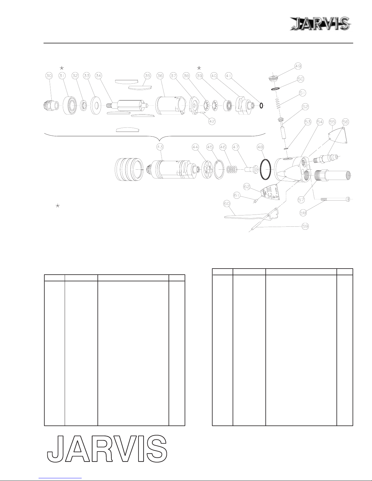
Refer
to the parts diagrams on pages 4-5 for
r
eferenced
items.
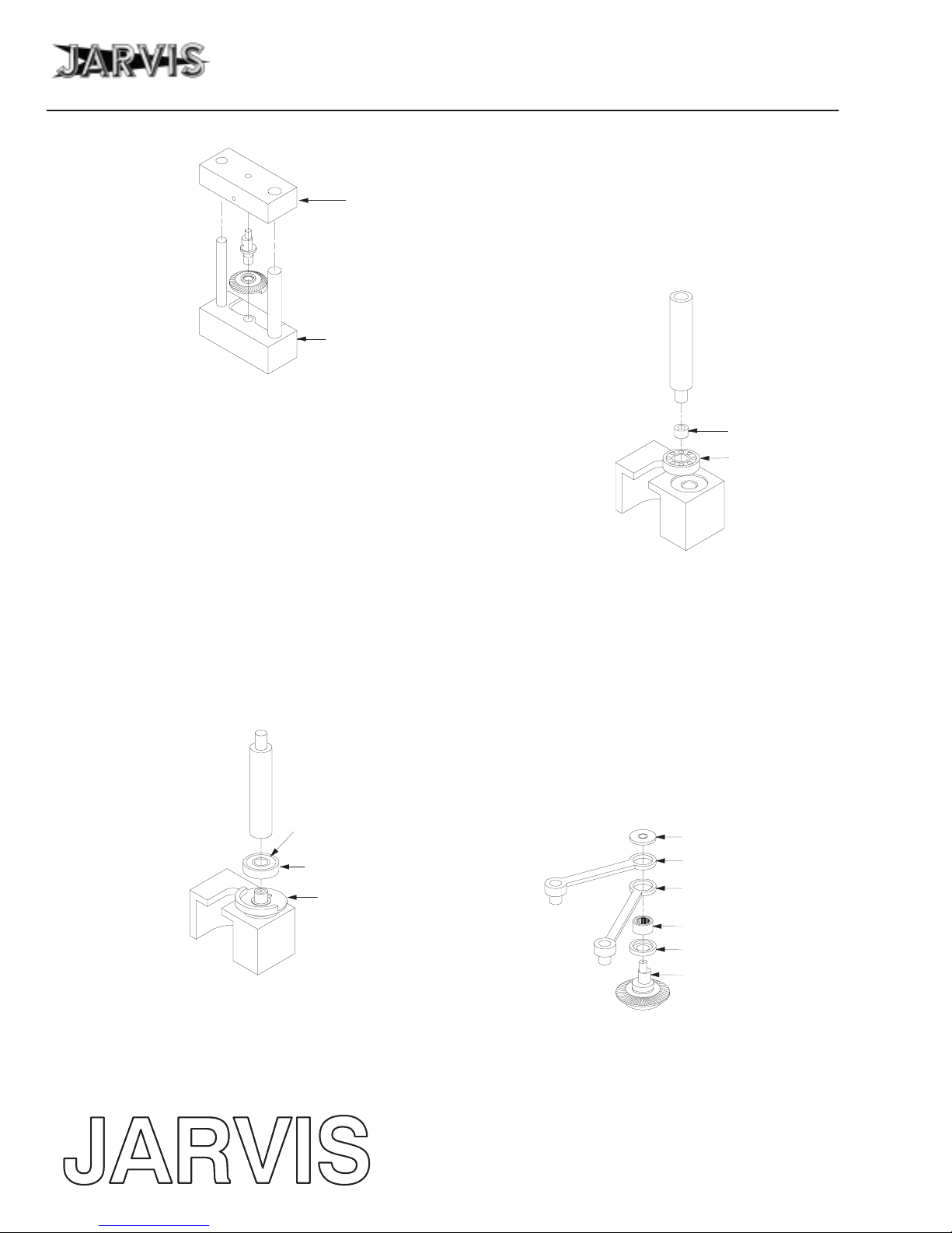
Refer
to the fixtur
e
diagrams above and the assembly/di
-
sassembly
diagrams within the text
for r
efer
enced fixtur
e
items.
1Three times per shift.
1.1 Grease all three grease fittings using Jarvis
Grease
Gun (part no. 8038001) and Jarvis Grease
(part no. 1062003 - Lubriplate FML-2).
1.1.1 Grease fittings (items 2 “A” and 2 “C”) with
two (2) pumps of grease.
1.1.2 Ensure
that grease is getting into the
eccentric
drive shaft (item 15), grease fitting (item 2
“B”) with four (4) pumps of grease.
2One time per shift.
2.1 Flush the air motor by squirting about 10 drops
of
Jarvis
air mist oil directly into the air inlet and
running the motor for about five seconds.
3One time per day.
W
ear cut pr
otective gloves when handling blades.
3.1 Make
sure that the compressed air supply is at the
proper
pressure and
that the lubricator oil is up to
the
full mark. (Use
JARVIS
Air Mist Lubricator
Oil;
if using a conventional air mist lubricator:
set
the
feed rate at 5 drops per minute; if
using
a mi
-
cro fog air mist lubricator*: set the feed rate at
100
drops per minute). *
Almost all air mist
lubri
-
cators ar
e micr
o fog air mist lubricators.
3.2 Remove cover screw (item 1).
3.3 Remove
items (3-8) by pulling up on and
turning
the blade set (item 8).
3.4 Push
bushing (item 26) in towards housing (item
24) to remove spacer (item 9).
3.5 Remove bushing (item 26).
3.6 Clean the dehider housing cover (item 11). Do
not
r
emove the cover
, mer
ely clean the
accessible
part of the cover.
3.7 Clean the blades with soap and water.
3.8 Sharpen the blades if necessary.
3.9 Spray or dip the dehider blades in USDA ap-
proved oil.
3.10 Grease the eccentric drive shaft (item 15)
through grease fitting (item 2 “B”) until grease
appears
through the dehider housing cover
(item
11).
3.11 Grease
the housing (item 24)
through grease fit
-
ting (item 2 “C”). Two (2) pumps of grease
should be sufficient.
3.12 Run the dehider without the blades for approxi-
mately one minute.
3.13 Insert bushing (item 26) into housing (item 24).
3.14 Place
spacer (item 9) into
dehider housing cover
(item 11).