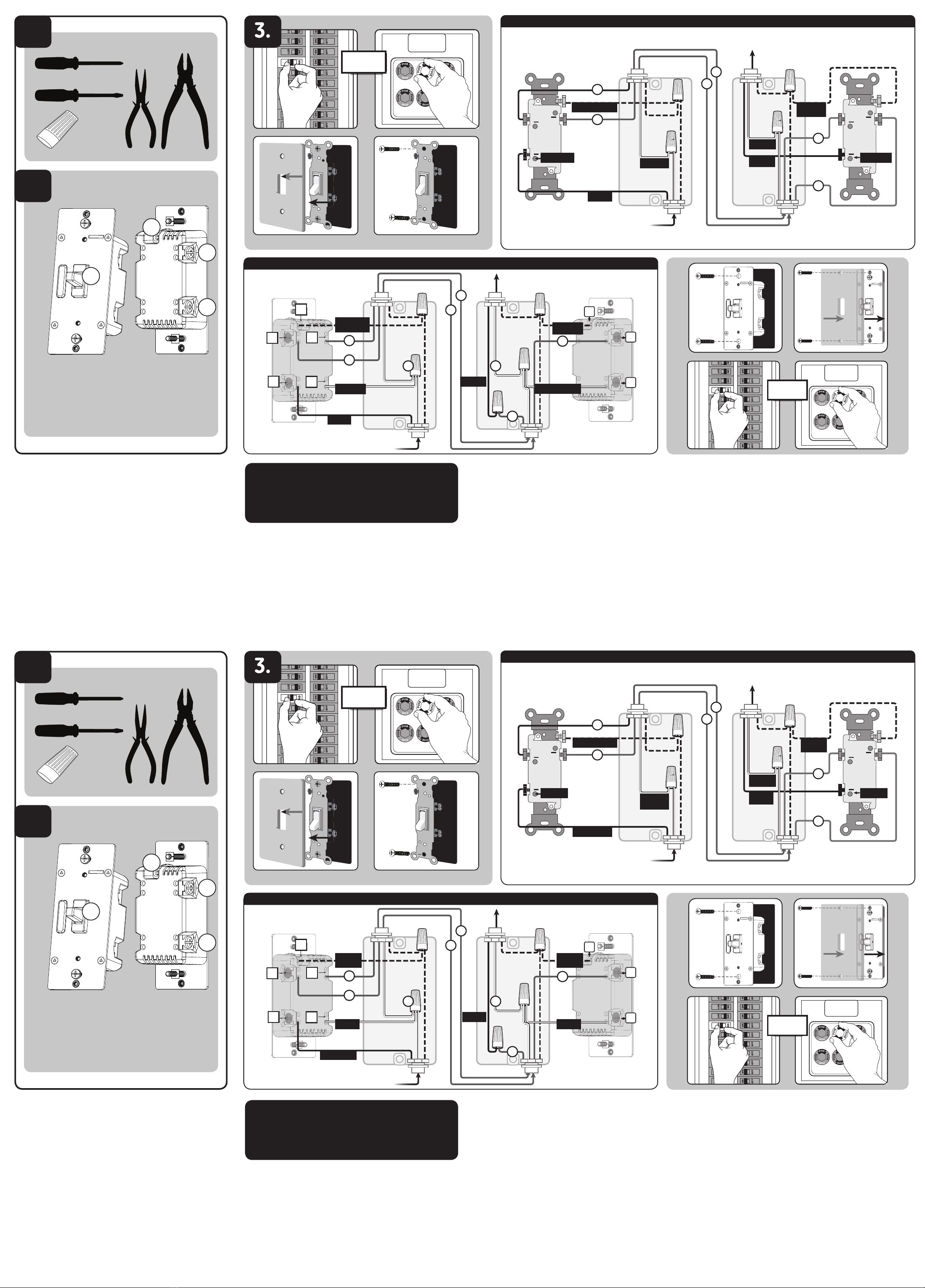
Tools you will need
1.
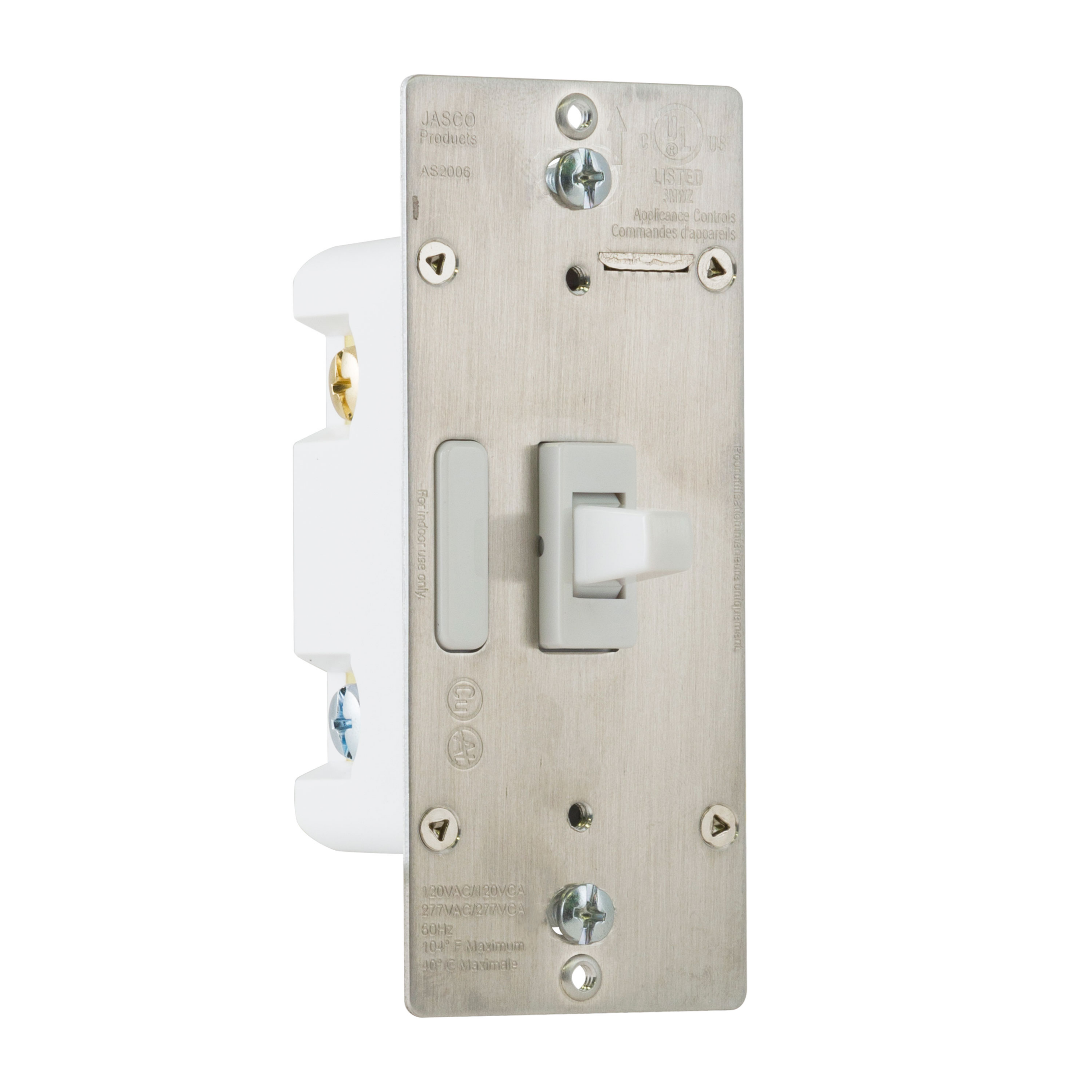
SPECIFICATIONS
AS2006
Power: 120/277VAC, 60Hz
Operating Temperature Range: 32-104° F (0-40° C)
For indoor use only
Type 1 action
Specications subject to change without notice due to continuing product improvement
SPÉCIFICATIONS
AS2006
Tension : 120/277VCA, 60Hz
Plage de températures de fonctionnement : De 32 à 104° F (de 0 à 40° C)
Utilisation intérieure uniquement
Intervention de type 1
En raison d’améliorations continues du produit, les spécications peuvent faire l’objet de
changements sans préavis
ESPECIFICACIONES
AS2006
Alimentación : 120/277VAC, 60Hz
Rango de temperatura de funcionamiento : 32-104° F (0-40° C)
Para espacios interiores solamente
Acción de tipo 1
Especicaciones sujetas a cambio sin aviso debido a continuas mejoras del producto
IMPORTANT!
The Jasco Add-on Switch is not wireless enabled and must be used
exclusively with one of the Jasco wireless devices (Z-Wave, ZigBee
or Bluetooth). It is not designed for stand-alone use to control an
electrical load. It does not have wireless functionality and does not
act as a repeater in your wireless control network
IMPORTANT!
L’interrupteur supplémentaire n’est pas sans l et doit être utilisé
exclusivement avec l’un des dispositifs sans l Jasco (Z-Wave,
ZigBee ou Bluetooth). Il n’est pas conçu pour être utilisé de façon
autonome en vue de commander une charge électrique. Il n’est pas
équipé de la fonction sans l et il ne joue pas le rôle de répétiteur
dans votre réseau de commande sans l.
¡IMPORTANTE!
El interruptor auxiliar no tiene funcionalidad inalámbrica y se debe
utilizar únicamente con uno de los dispositivos inalámbricos Jasco
(Z-Wave, ZigBee o Bluetooth). No ha sido diseñado para usarse
de manera separada para controlar una carga eléctrica. No tiene
funcionalidad inalámbrica y no funciona como repetidor en una red
de control inalámbrico.
MANUAL • MANUEL • MANUAL
46561
AS2006
In-Wall
Add-on Switch
Montage mural
Interrupteur
supplémentaire
Interruptor auxiliar
de pared
All brand names shown are trademarks of their
respective owners.
Tous les noms de marque illustrés sont des
marques de commerce de leurs propriétaires
respectifs.
Todas las marcas que aparecen aquí son marcas
registradas de sus respectivos dueños.
MADE IN CHINA/FABRIQUÉ EN CHINE/HECHO EN CHINA
DISTRIBUTED BY JASCO PRODUCTS COMPANY LLC,
10 E. MEMORIAL RD., OKLAHOMA CITY, OK 73114.
©JASCO 2019 | 46561 | AS2006 | 04/03/19 v1
If you have any problems or questions, contact our U.S.-based Consumer Care at
1-800-654-8483, option 1, Monday–Friday, 7AM–8PM CST.
For the most up-to-date product support, accessories, electronic (PDF)
format manuals and more, visit www.byjasco.com/support.
• No user-serviceable parts in this unit.
Si vous avez des problèmes ou des questions, communiquez avec notre
équipe de soutien technique au 1-800-654-8483, option 1, du lundi au vendredi,
de 7 h à 20 h (HNC).
Pour le soutien relatif aux produits le plus à jour, les accessoires, les manuels en
format électronique (PDF) et plus encore, visitez le site www.byjasco.com/support.
• Aucune des pièces de ce dispositif ne peut être réparée par l’utilisateur.
Si tiene problemas o dudas, comuníquese con nuestro equipo
técnico al número 1-800-654-8483, opción 1, de lunes a viernes,
de 7 a.m. a 8 p.m., hora estándar del centro (CST).
Para recibir el soporte técnico más actualizado sobre productos, accesorios,
manuales en formato digital (PDF), entre otros, visite www.byjasco.com/support.
• Esta unidad no contiene piezas que el usuario pueda reparar.
DO NOT RETURN THIS
PRODUCT TO THE STORE
NE RETOURNEZ PAS
CE PRODUIT AU MAGASIN
NO DEVUELVA ESTE
PRODUCTO A LA TIENDA
STOP
WARRANTY
Jasco Products Company warrants this product to be free from manufacturing defects for two
years from the original date of consumer purchase. This warranty is limited to the repair or
replacement of this product only and does not extend to consequential or incidental damage to
other products that may be used with this product. This warranty is in lieu of all other warranties,
expressed or implied. Some states do not allow limitations on how long an implied warranty lasts
or permit the exclusion or limitation of incidental or consequential damage, so the above
limitations may not apply to you. This warranty gives you specic rights, and you may also have
other rights which vary from state to state. Please contact our U.S.-based Consumer Care at
1-800-654-8483 (option 1) between 7AM – 8PM CST or www.byjasco.com if the unit should
prove defective within the warranty period.
GARANTIE
Jasco Products Company garantit que ce produit est exempt de tout défaut de fabrication pour
une période de deux ans à compter de la date de l’achat original par l’acheteur. Cette garantie
se limite exclusivement à la réparation ou au remplacement de ce produit et n’est pas applicable
aux dommages indirects ou accessoires survenus sur d’autres produits utilisés avec ce produit.
Cette garantie se substitue à toute autre garantie expresse ou implicite. Certains États ne
permettent pas de restrictions quant à la durée d’une garantie implicite ou permettent l’exclusion
ou la limitation des dommages indirects et accessoires; il se peut, par conséquent, que cette
garantie ne s’applique pas dans votre cas. Cette garantie vous confère des droits juridiques
précis; vous pouvez jouir d’autres droits qui peuvent varier d’un État à l’autre. Veuillez
communiquer avec le service à la clientèle au 1-800-654-8483 (option 1) entre 7 h et 20 h
(heure normale du Centre) ou www.byjasco.com si l’appareil s’avère défaillant au cours de la
période de garantie.
GARANTÍA
Jasco Products Company garantiza que este producto está libre de defectos de fabricación
durante un periodo de dos años a partir de la fecha original de compra por parte del
consumidor. Esta garantía se limita a la reparación o sustitución de este producto solamente y
no se extiende a daños derivados o accidentales causados a otros productos que se usen con
esta unidad. Esa garantía remplaza a todas las demás garantías expresas o implícitas. Algunos
estados no autorizan limitaciones en cuanto a la duración de una garantía implícita ni permiten
la exclusión o limitación por daños accidentales o derivados; por lo tanto, puede que las
anteriores limitaciones no apliquen en su caso. Esta garantía le da a usted derechos
especícos, y otros que usted puede tener y que varían según el estado en el que usted reside.
Si la unidad resultare defectuosa dentro del periodo de garantía, comuníquese por favor con
Atención al Cliente en el 1-800-654-8483 (opción 1) entre 7 y 20 h, Hora del Centro, o
www.byjasco.com.
Jasco Products Company LLC, Building B
10 E. Memorial Rd. Oklahoma City, OK 73114.
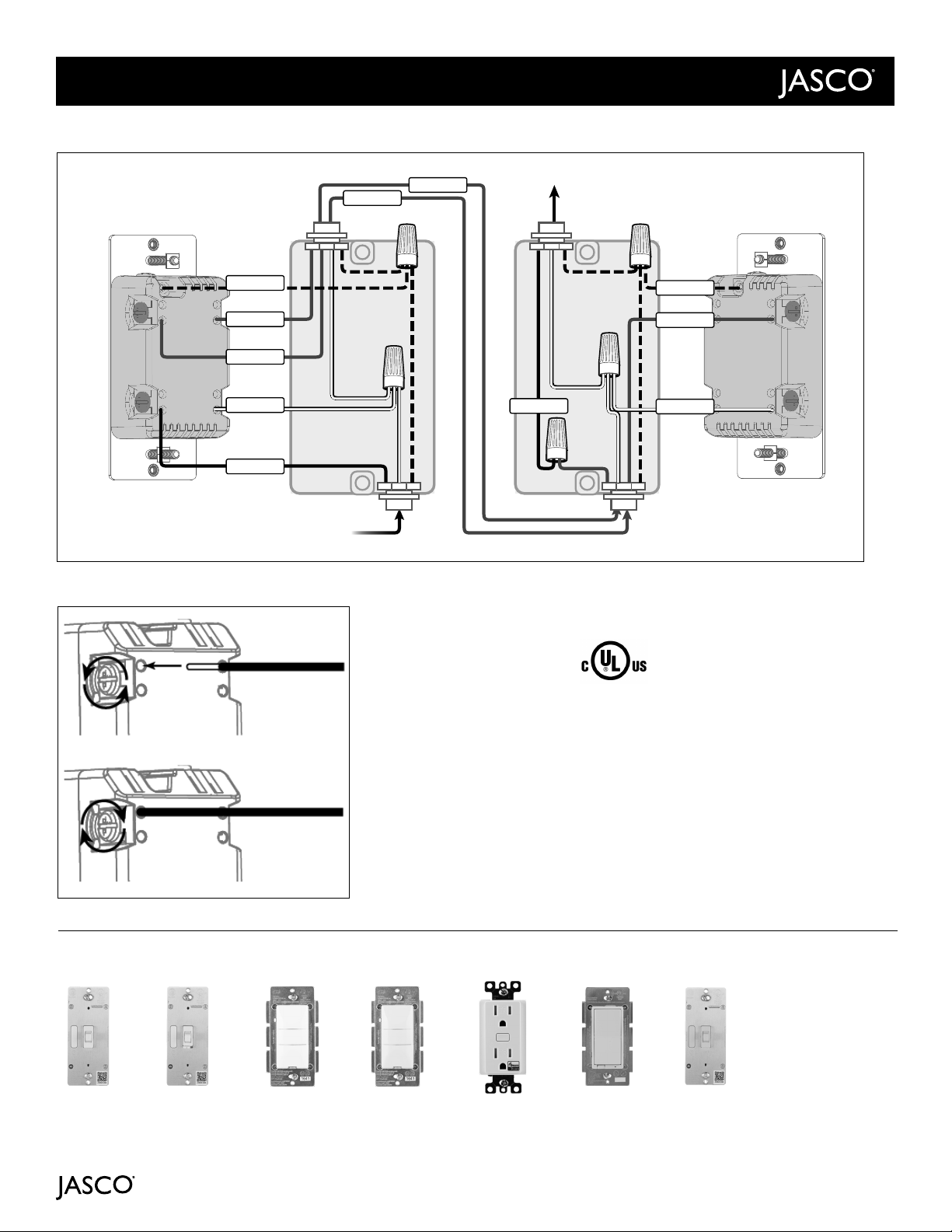
2.
*The add-on switch takes the
characteristics of the primary
Z-Wave switch. Refer to the
primary switch’s manual for
instructions.
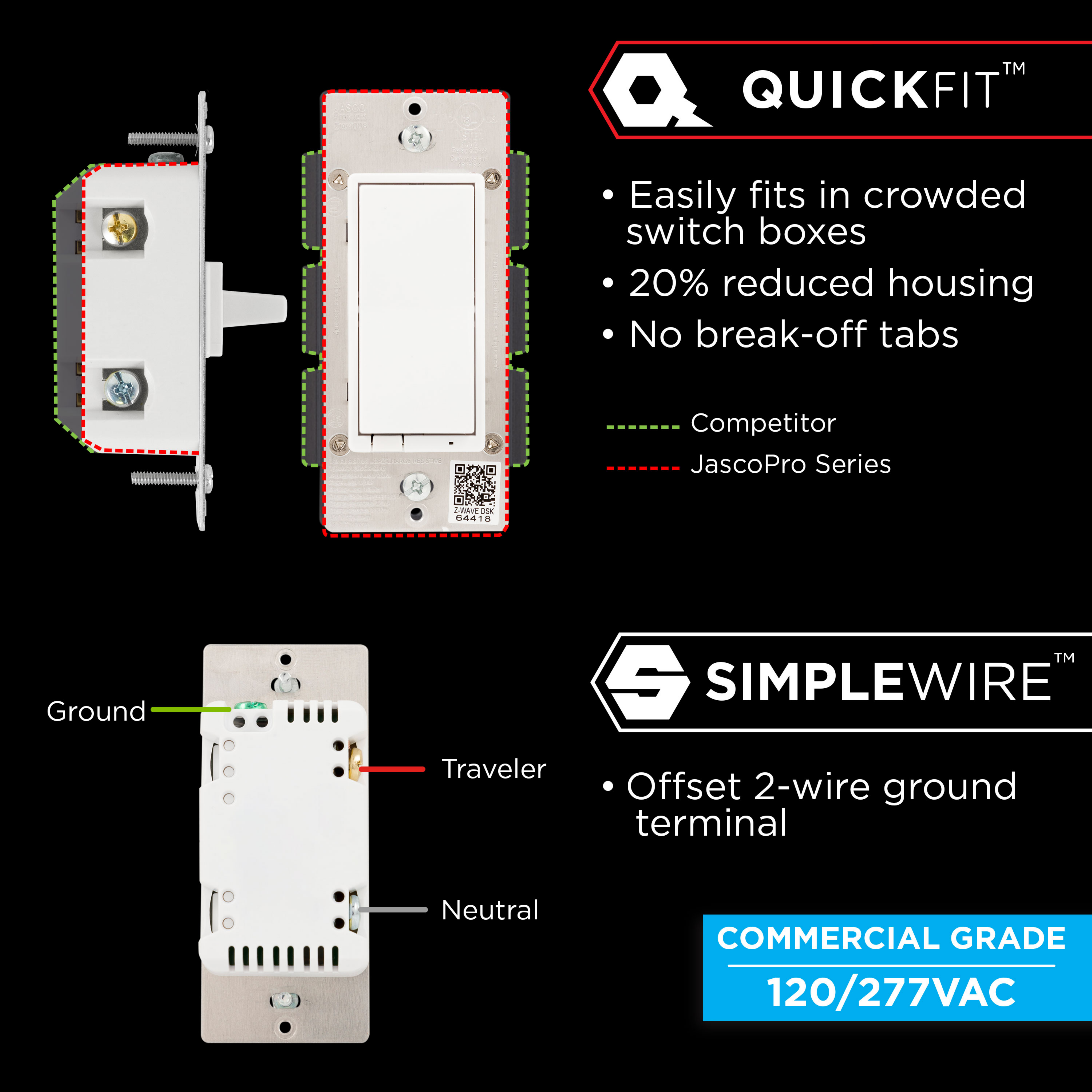
BB. Neutral (White)
CC. Ground (Green/Bare)
DD. Traveler (Red/Other)
*
DD
CC
BB
Standard 3-Way Switch
T2
T1
T1
T2
T2
T1
NEUTRALS
NEUTRALS
COMMON COMMON
GROUND
Line
Switch
Load
Switch
Out to Light (Load)
Out to Load Switch
In from Line Switch
From Breaker Box
GROUND
LOAD
BB
DD
CC
T2
AA
T1
From Breaker Box
In from Line Switch
Out to Light (Load) Load Switch
(Add-on Switch)
T2
T1
T2
T1
D
E
C
F
B
A
JUMPER
GROUND GROUND
Out to Load Switch
Line Switch
(Primary Switch)
LINE
Jasco-branded Switch
LOAD
JUMPER
WARNING — SHOCK HAZARD
Turn OFF the power to the branch circuit for the switch and lighting xture at the service
panel. All wiring connections must be made with the POWER OFF to avoid personal injury
and/or damage to the switch. This device is intended for installation in accordance with
the National Electric Code and local regulations in the United States or the Canadian
Electrical Code and local regulations in Canada. If you are unsure or uncomfortable about
performing this installation, consult a qualied electrician.
IMPORTANT!
3-way switches can be wired in dierent ways. These instructions explain the most common
method. If you have diculty with the instructions or your home wiring, contact a licensed
electrician for assistance.
1. Shut o power to the circuit at circuit breaker or fuse box.
IMPORTANT! Verify power is OFF to switch box before continuing.
2. Remove both wallplates.
3. Remove the switch mounting screws.
4. Carefully remove the switch from each switch box location. DO NOT disconnect the
wires yet.
5. Identify switch connected to fuse box. This is the “line switch.” Label wire connected to
common terminal, “LINE.”
6. Identify switch connected to lighting/xture. This is the “load switch.” Label wire
connected to common terminal, “LOAD.”
Switch connected to lighting “load switch”
Replacing standard switch with Jasco Add-on Switch
1. Disconnect all wires on existing switch.
2. Locate neutral wires found inside switch box. These are typically a bundle of white wires
in the back of the box. Remove wire nut securing them (AA).
3. Locate jumper wire included in packaging of primary switch. Connect with neutral wires
and secure with wire nut (AA).
4. Connect opposite end of jumper wire to NEUTRAL terminal on Z-Wave Add-on Switch (BB).
5. Connect ground wire (bare/copper/green) to GROUND terminal on Z-Wave
Add-on Switch (CC).
6. Locate the same colored wire you wrote down in the switch box (T1). Using a wire nut,
secure it only to the wire you labeled “LOAD.”
7. Connect the remaining wire to TRAVELER terminal on the Z-Wave Add-on Switch (DD).
This will be the same color as the wire connected to TRAVELER terminal on the Z-Wave
primary switch.
Attach switch to box
1. Place both switches into their respective switch boxes being careful not to
pinch or crush wires.
2. Secure each switch to the box using the supplied screws.
3. Mount each switch wallplate.
4. Reapply power to the circuit at fuse box or circuit breaker and test the system.
Observe important wiring information
IMPORTANT! This add-on switch is rated for and intended to only be used with
copper wire.
Wire gauge requirements
Use 14AWG or larger wires suitable for at least 80°C for supplying line (hot), load, neutral,
ground and traveler connections.
Wire strip length
Attach using the enclosure’s holes, strip insulation 5/8in. (16mm).
UL species the tightening torque for the screws is 14Kgf-cm (12lbf-in).
Switch connected to fuse box “line switch”
Replacing standard switch with Jasco Z-Wave primary switch
1. Disconnect all wires on existing switch.
2. Locate neutral wires found inside switch box. These are typically a bundle of white wires
in the back of the box. Remove wire nut securing them (A).
3. Locate jumper wire included in packaging of primary switch. Connect with neutral wires
and secure with wire nut (A).
4. Connect opposite end of jumper wire to NEUTRAL terminal on Z-Wave primary switch (B).
5. Connect wire labeled “LINE” to one of the LINE/LOAD terminals on Z-Wave primary
switch (C).
6. Connect ground wire (bare/copper/green) to GROUND terminal on Z-Wave primary
switch (D).
7. Connect one of the two remaining wires (T1) to the other LINE/LOAD terminal on Z-Wave
primary switch (E). Write down the color of the wire. You will need this when installing the
add-on switch.
8. Connect the remaining wire (T2) to TRAVELER terminal on the Z-Wave primary switch (F).
OR
OR
LINE
READ IT OR WATCH IT
Read instructions or watch easy-to-follow video.
Scan QR code or visit https://goo.gl/rMxGK3.
Z-Wave® Certied Wireless Lighting Control
Certié Z-Wave®Commande d’éclairage sans l
Control inalámbrico para iluminación certicado por Z-Wave®
ezzwave.com
Scan to view
installation guide
Balayez ce code pour
consulter le guide
d’installation.
Escanear para ver
la guía de instalación
14319
ZW4003
In-Wall
Smart Dimmers
Plug-in
Smart Dimmers
In-Wall
Add-on Switches
Purchase additional items at
EZzwave.com, EZzigbee.com or visit your local retailer.
In-Wall Motion
Switch or Dimmer
Plug-in
Smart Switches
In-Wall
Smart Switches
Enbrighten
Smart LED Bulb
In-Wall
Smart Fan Control
Hinge Pin
Smart Door Sensor
Direct Wire,
40A Outdoor
Smart Switch
Portable
Smart Multi
Sensor
In-Wall
Tamper-Resistant
Smart Outlet
Plug-in
Outdoor Smart
Switch
Convert any smart control* to a multi-location switch
*For a list of compatible devices, visit ezzwave.com
Smart Control Add-on Switches
To purchase an add-on switch or for more
details, visit ezaddonswitch.com.
Each smart control supports
up to 4 add-on switches
ezaddonswitch.com
RIESGO DE INCENDIO
RIESGO DE DESCARGA ELÉCTRICA
RIESGO DE QUEMADURAS
CONTROL DE EQUIPOS
ELECTRODOMÉSTICOS
PRECAUCIÓN:
USAR EXCLUSIVAMENTE PARA CONTROLAR
BOMBILLAS CFL/LED INCANDESCENTES O
ATENUABLES
NO SUPERE LOS VALORES NOMINALES
ELÉCTRICOS
NO USAR PARA CONTROLAR DISPOSITIVOS
EN LOS QUE EL FUNCIONAMIENTO NO
INTENCIONADO PODRÍA PROVOCAR
SITUACIONES PELIGROSAS (LÁMPARAS DE
CALEFACCIÓN, LÁMPARAS SOLARES, ETC.)
NO UTILICE PARA CONTROLAR
TOMACORRIENTES
USE SOLAMENTE EN INTERIORES
RISK OF FIRE
RISK OF ELECTRICAL SHOCK
RISK OF BURNS
CONTROLLING APPLIANCES
CAUTION:
DO NOT EXCEED RATINGS
DO NOT USE TO CONTROL ANY DEVICE
WHERE UNINTENDED OPERATION COULD
CAUSE UNSAFE CONDITIONS (HEAT LAMP,
SUN LAMP, ETC.)
DO NOT USE TO CONTROL RECEPTACLES
FOR INDOOR USE ONLY
RISQUE D’INCENDIE
RISQUE DE CHOC ÉLECTRIQUE
RISQUE DE BRÛLURES
COMMANDE DES APPAREILS
ATTENTION:
UTILISER SEULEMENT POUR COMMANDER
LES AMPOULES À DEL ET FLUOCOMPACTES À
INCANDESCENCE OU À INTENSITÉ RÉGLABLE
NE PAS DÉPASSER LES CARACTÉRISTIQUES
NOMINALES
NE PAS UTILISER POUR COMMANDER
DES APPAREILS POUR LESQUELS UN
FONCTIONNEMENT IMPRÉVU POURRAIT
ENTRAÎNER DES CONDITIONS DANGEREUSES
(LAMPE À RAYONS INFRAROUGES, LAMPE
SOLAIRE, ETC.)
NE PAS UTILISER POUR COMMANDER LES
PRISES DE COURANT
POUR UTILISATION INTÉRIEURE UNIQUEMENT
AVERTISSEMENT
WARNING ADVERTENCIA
NOT FOR USE WITH MEDICAL OR LIFE-
SUPPORT EQUIPMENT
Z-WAVE ENABLED DEVICES SHOULD NEVER
BE USED TO SUPPLY POWER TO OR CONTROL
THE ON/OFF STATUS OF MEDICAL OR LIFE-
SUPPORT EQUIPMENT.
NE PAS UTILISER AVEC UN ÉQUIPEMENT
MÉDICAL OU DE SURVIE
LES DISPOSITIFS COMPATIBLES AVEC LA
TECHNOLOGIE Z-WAVE NE DEVRAIENT
JAMAIS ÊTRE UTILISÉS POUR ALIMENTER
OU COMMANDER LA MISE EN MARCHE OU
L’ARRÊT DE L’ÉQUIPEMENT MÉDICAL OU DE
SURVIE.
SE PROHÍBE SU EMPLEO EN
EQUIPO MÉDICO O EQUIPO PARA EL
MANTENIMIENTO DE LAS FUNCIONES
VITALES
LOS DISPOSITIVOS Z-WAVE NUNCA SE
DEBEN USAR PARA SUMINISTRAR ENERGÍA
ELÉCTRICA AL EQUIPO MÉDICO O AL EQUIPO
PARA EL MANTENIMIENTO DE FUNCIONES
VITALES, NI PARA CONTROLAR EL ESTADO
DE ENCENDIDO O APAGADO DE DICHOS
EQUIPOS.
Insert wires into holes, do not
wrap wires around screws.
Do not remove screws.


 User manual")