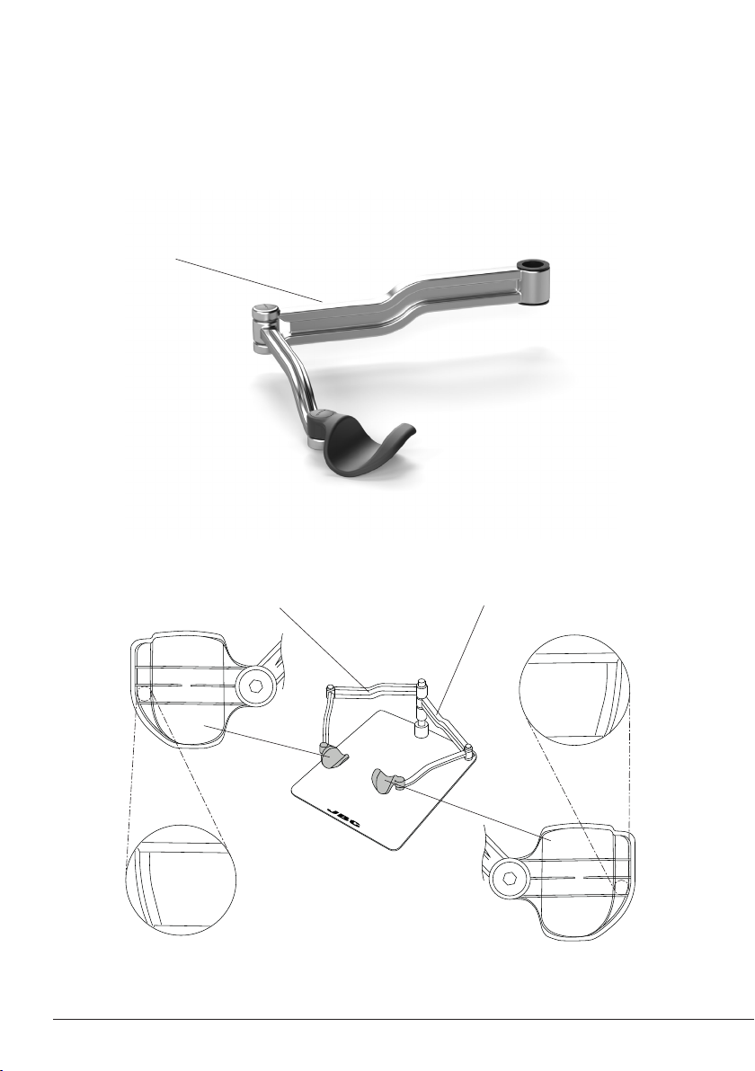
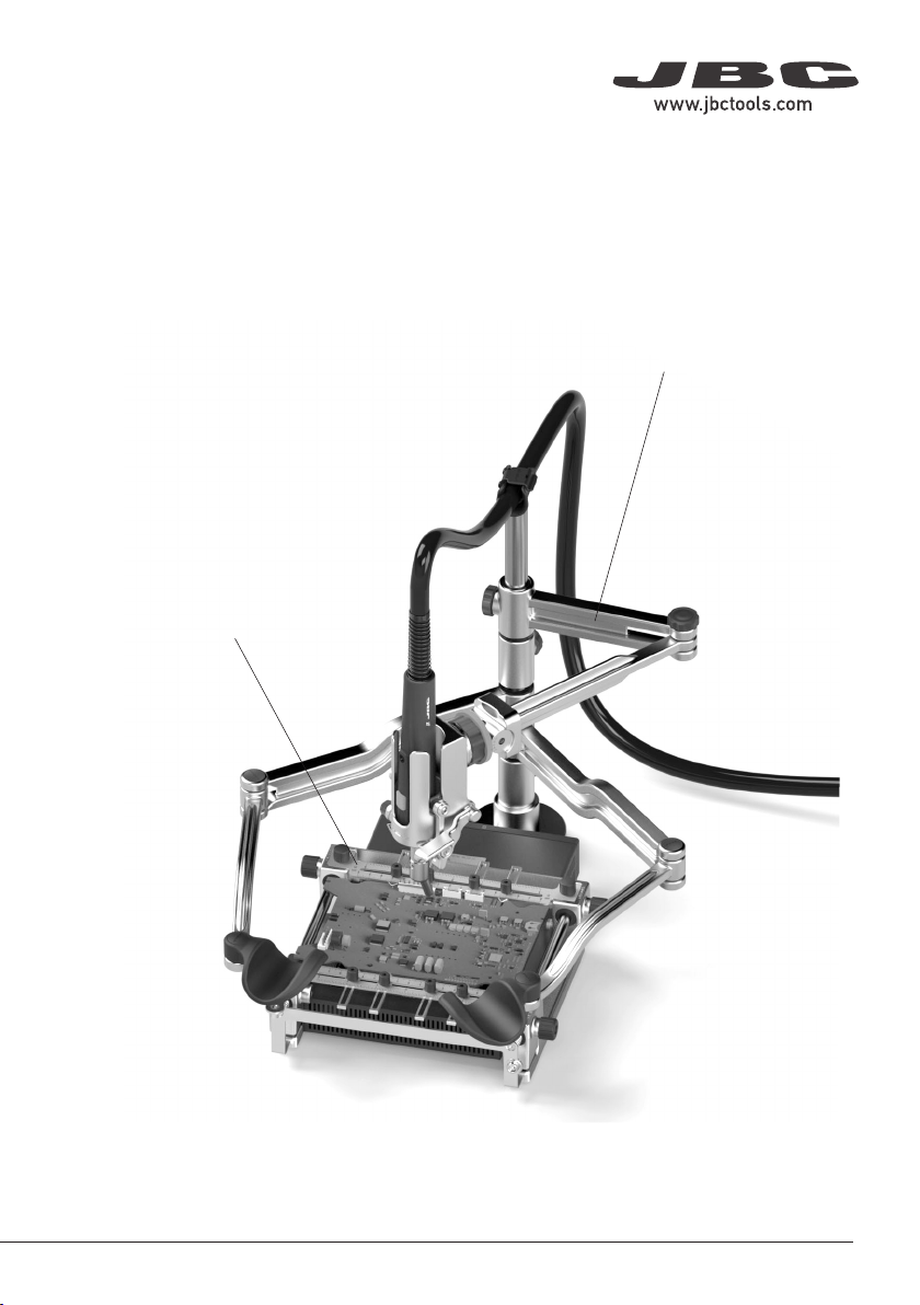
Sliding Parts
Maintenance
- Check periodically that RHS is clean,
especially the sliding parts and the shaft.
- Use a damp cloth when cleaning. Alcohol
can only be used to clean the metal parts.
- Replace any defective damaged parts.
Use original JBC spare parts only.
Not leave up RHN over the preheater
when the preheater is working.
Safety
- Do not use the equipment for any purpose other than PCB rework.
- The temperature of accessible surfaces may remain high after the unit is turned off. Handle with care.
- Be careful with the fumes produced when soldering.
- Keep your workplace clean and tidy. Wear appropriate protection glasses and gloves when
working to avoid personal harm.
- Not leave up the arms directly above heat surfaces.
- Utmost care must be taken with liquid tin waste which can cause burns.
- This appliance can be used by children over the age of eight as well as persons with reduced
physical, sensory or mental capabilities or lacking experience provided that they have been given
adequate supervision or instruction concerning use of the appliance and understand the hazards
involved. Children must not play with the appliance.
- Maintenance must not be carried out by children unless supervised.
It is imperative to follow safety guidelines to prevent electric shock, injury,
fire or explosions.
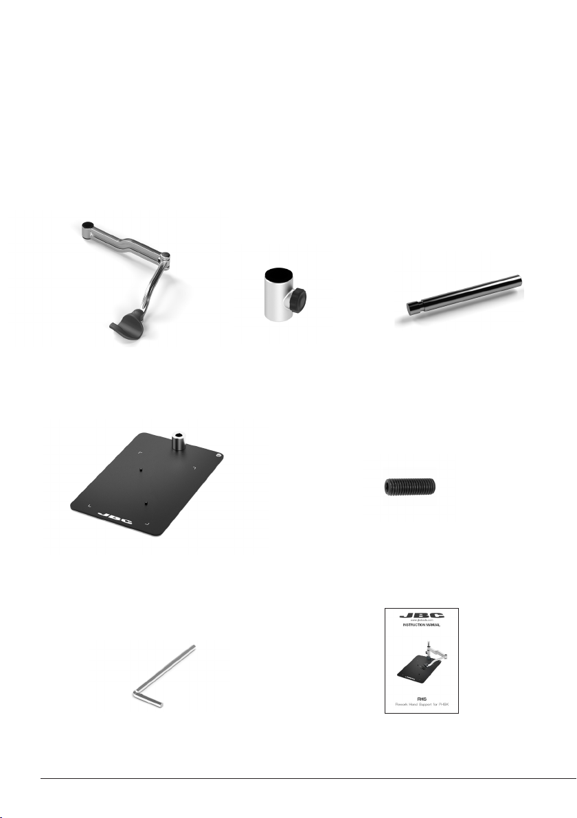
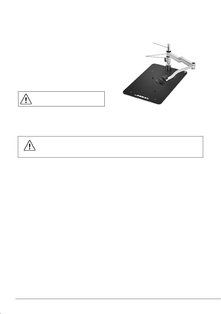
Shaft
8