Contents
1
2
3
4
5
6
7
8-9
10
11
12
13
14
Contents
Wiring
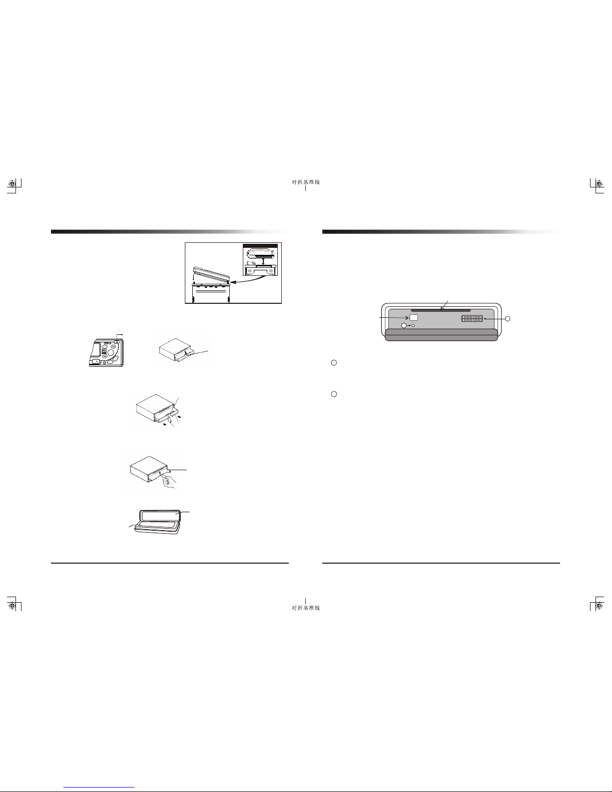
Installing and Removing the Detachable Face
Important Notes
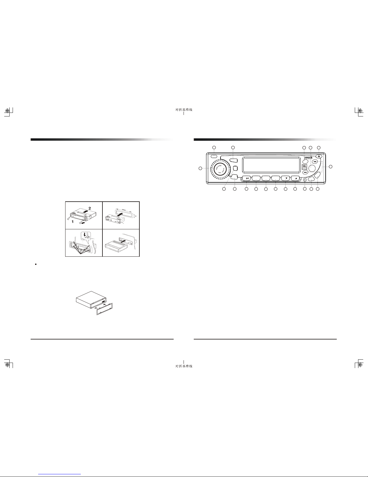
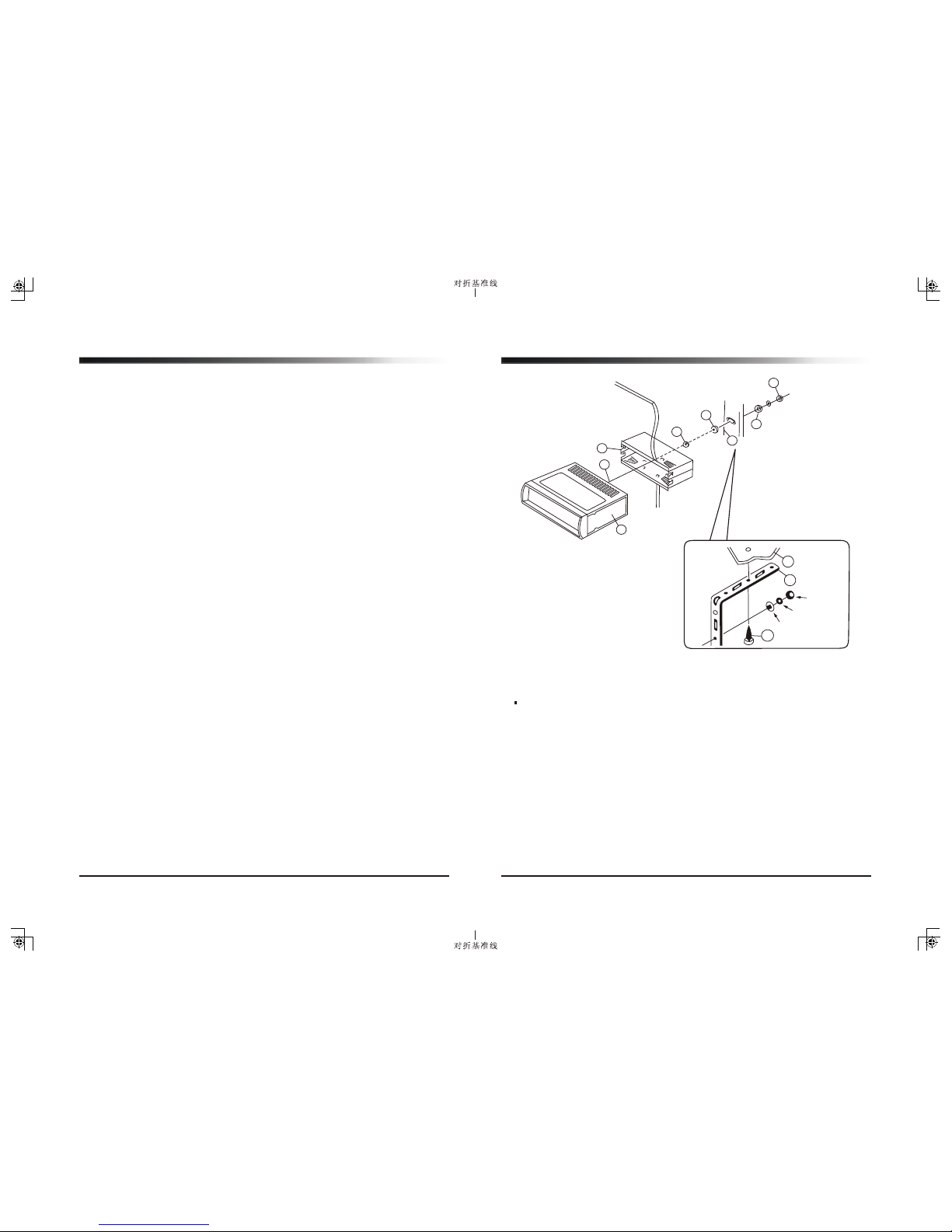
Installation
Supporting the Unit
Identification of Controls and Functions
Controls
Station Tuning
Operating the CD & CD Changer
Precautions and Maintenance
Trouble Shooting Guide & Specifications
Quick Reference Guide for SIRIUS
Identification
PLEASE NOTE: In order to receive Sirius Satellite radio broadcast, you must install
JBL SIR as well as a satellite antenna (both sold separately).
What is SIRIUS Satellite Radio?
SIRIUS, headquartered in New York, offers over 120 channels of digital quality radio
transmitted across the continental US from three high-tech satellites. Along with offering
a full spectrum of music genres, users can also listen to popular news, entertainment
and sports channels. SIRIUS currently offers 65 music channels, 24 news channels
(including traffic and weather), 7 sports channels (including two dedicated play-by-play
channels) and 24 talk / entertainment channels.
For more information on SIRIUS, visit siriusradio.com.
3.0
1
¦Ì
Quick Reference Guide for Sirius
14
1. To Access Satellite Radio
-Press MODE button until SIRIUS appears on the LCD.
- While in any mode other than SIRIUS, simply press SH.SR to enter SIRIUS mode.
2. For Direct Channel Entry
While in SIRIUS mode, press MODE button for over 1.5 seconds to enter Direct Mode. At that
point, the display will show Channel_ _ _ Simply enter the desired number to go directly to
the channel (example: 123).
3. To Access SIRIUS ID number
In SIRIUS mode, press MODE button for over 1.5 seconds, Channel_ _ _ will display on LCD,
enter 000 to display your SIRIUS ID number. SID followed by 12 digits will appear on the
LCD. To exit the display with the SIRIUS ID, press any button other than the PWR button.
4. To Enter Category Mode
While in SIRIUS mode, press BD/FN button for over 1.5 seconds to enter Category mode.
The Category icon will appear on the LCD. Momentarily press Tune up/down button to switch
between category group. To change categories, press and hold Tune up/down button for 1.5
seconds. To return to Direct mode, press and hold BD/FN button until the display says DIRECT.
5. To Preset Channels (up to 20 presets):
You can save up to 20 channels in the memory for direct mode and up to 10 channels in
category mode. There are two possible ways to preset:
- Press MODE button for over 1.5 seconds until Channel_ _ _ displays on LCD. Then use
the numeral key to directly enter what ever channel you would like to store (example:104).
Press the preset button where you would like to store the channel for over 1.5 seconds to
save it to memory.
2. Use TUNE UP/DN button to find a channel you would like to store. Press the preset button
where you would like to store the channel for over 1.5 seconds to save it to memory.
6. To Display Song Title or Artist
In SIRIUS mode, repeatedly press and hold SH.SR button for 1.5 seconds to switch between
song title, artist and composer on the display.
7. For Parental Lock Out Programming
- In SIRIUS mode, select the channel that you want to lock out. Press SH.SR to show SHIFT
icon, then simply press numeral 5 button. It has been locked when Locked Channel appears
on the display.
- To temporarily unlock a channel, manually tune to the channel. When prompted, the display
will read CHANNEL LOCKED, then it will display CODE. Enter your password and the channel
will be unlocked until you change to another channel.
- To permanently unlock a channel, after temporarily unlocking the channel press SH.SR
button to show SHIFT icon on LCD, then simply press numeral 5 button. Then enter your
password again, the channel becomes totally unlocked when LOCK RELEASE displays.
8. To Change the Password (CODE)
In SIRIUS mode, press and hold SEL button, then momentarily press SEL repeatedly until
CODE displays on LCD. Enter your current password first, once you see NEW CODE displays,
enter your new 4-digit password. Now display will show UPDATE which means the system
accepted your new password.
Note: If power is completely removed from stereo, the password will revert back to 0000.