I.
INTRODUCTION
The decade of the 1980’s saw many improvements in the quality of cinema sound. Dolby
Laboratories had begun the cinema sound revolution during the middle 1970’s with the introduction of
noise reduction and equalization of cinema loudspeaker systems. In 1981, JBL demonstrated the first
flat power response loudspeaker systems at the Academy of Motion Picture Arts and Sciences. In
1983, Lucasfilm introduced the
THX@
system, along with their program of cinema certification. As the
1980’s progressed, Dolby stereo optical sound tracks gained in favor, increasing the number of stereo
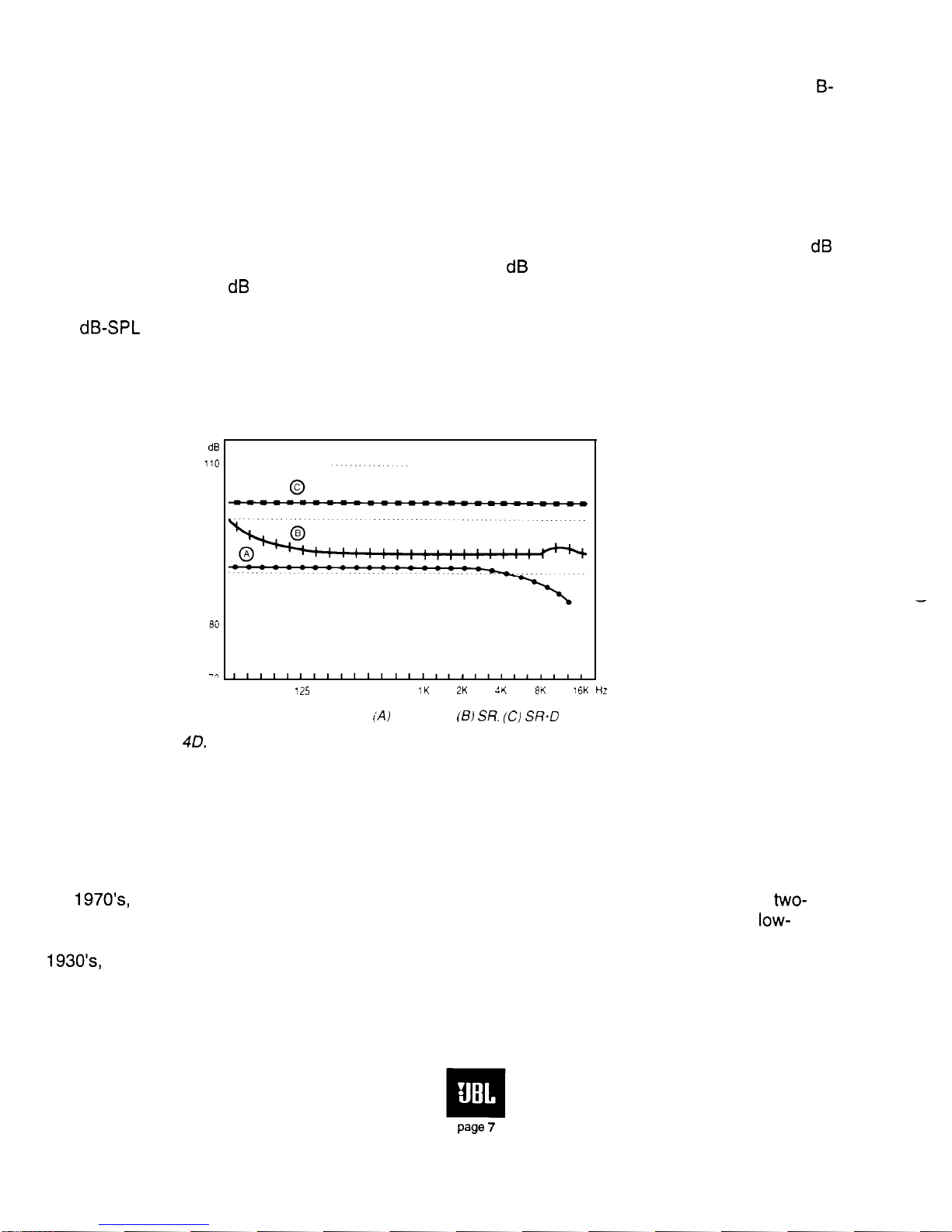
houses significantly. The application of Dolby Spectral Recording (SR) to cinema release prints
represented another step forward in sound quality.
By the mid
199Os,
three digital systems had been introduced into the cinema, Dolby SR-D.
Digital Theater Sound (DTS), and Sony Dynamic Digital Sound (SDDS). These systems have similar
digital performance characteristics, and they all provide analog stereo optical tracks for overall
compatibility and operational redundancy, should the digital portion of the system fail, or momentarily
go into a mute mode. DTS makes use of a synchronized CD-ROM for its digital program, while the
other two include the digital information on the print itself.
As new cinema complexes are being pianned and constructed, acoustical engineers are now
more than ever before being engaged to deal with problems of architectural acoustics and sound
isolation between adjacent exhibition spaces. More attention is being paid to the specification of
sound equipment and its careful integration into the cinema environment.
JBL has a strong commitment to the cinema sound market. We have become the
acknowledged leader in the field, and our products are routinely specified for major studios and
post-
production houses throughout the world. JBL continues its rapid pace in new product development
aimed at increasing performance levels in the cinema.
This manual has several goals. First, it will provide a background in basic systems concepts,
and then move on to acoustical considerations in the cinema. The subject of electroacoustical
specification will be discussed, as will the problems of mounting and aiming of the components.
Electrical interface and system checkout will be covered in detail. JBL believes that the more dealers
and installers know about the basics of sound in the cinema, the better will be the results of their work
in all areas.
II. BASIC SYSTEM CONCEPTS
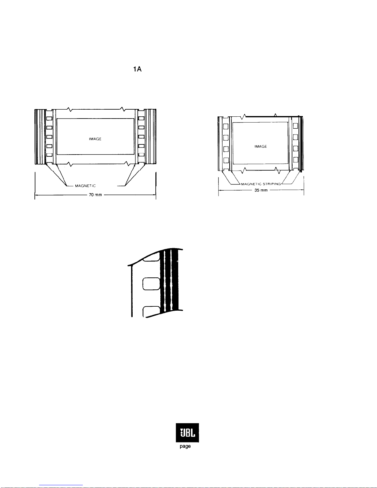
A. Analog Film Formats
There are two film sizes for theatrical exhibition: 35 mm and 70 mm. The most common
projection image aspect ratios (horizontal vs. vertical) for 35 mm can be either 1.851 (“flat”) or
2.35:1
(“scope”). Seventy mm prints are normally projected at a ratio of
2.2:1.
The advantages of 70 mm
have, in the past, been the availability of six magnetic tracks and large image area. The cost of a 70
mm print is quite high, and these prints have normally been made in limited quantities for exhibition in
premier houses in large metropolitan locations. Today, the general practice with 70 mm is to use three
channels behind the screen (left, center, and right) and a single surround channel feeding multiple
page
2