JBL Simply Cinema SCS260.5 User manual

SCS260.5/230 and
SCS260.6/230
SURROUND CINEMA
SPEAKERS
OWNER’S GUIDE
®
The SCS260.6 system is shown here.

2
READ FIRST! Important Safety Precautions!
1. Unpacking: Check the product
carefully. If it has been damaged in
transit, report the damage immedi-
ately by calling your dealer and/or the
shipping company that delivered it.
2. Connections: Whenever changing,
connecting or disconnecting signal or
power cables etc., always turn off all
equipment. This prevents transients
from entering the equipment and pre-
vents electrical energy from reaching
you. Keep all connections out of the
reach of children. Before moving the
unit, be certain to disconnect any
interconnection cords with other
components, and make certain that
you disconnect any powered units
from the AC outlet.
3. Read Instructions. All the safety
and operating instructions should be
read before the product is operated.
4. Retain Instructions. The safety and
operating instructions should be
retained for future reference.
5. Heed Warnings. All warnings on the
product and in the operating instruc-
tions should be adhered to.
6. Follow Instructions. All operating
and use instructions should be fol-
lowed.
7. Water and Moisture. The product
should not be used near water – for
example, near a bathtub, washbowl,
kitchen sink, laundry tub, in a wet
basement, or near a swimming pool,
and the like.
8. Accessories. To ensure proper
operation and to avoid the potential
for safety hazards, place the unit on a
firm and level surface. When placing
the unit on a shelf, be certain that the
shelf and any mounting hardware can
support the product’s weight.
Do not place this pro-
duct on an unstable
cart, stand, tripod,
bracket, or table. The
product may fall,
causing serious
injury to a child or adult, and serious
damage to the product. Use only with
a cart, stand, tripod, bracket, or table
recommended by the manufacturer,
or sold with the product. Any mount-
ing of the product should follow the
manufacturer’s instructions, and
should use a mounting accessory
recommended by the manufacturer.
9. Wall or Ceiling Mounting. The
product should be mounted on a wall
or ceiling only when and as recom-
mended by the manufacturer.
10. Cleaning. Unplug this product
from the wall outlet before cleaning.
Do not use liquid cleaners or aerosol
cleaners. Use a dry cloth for clean-
ing.
11. Attachments. Do not use attach-
ments not recommended by the prod-
uct manufacturer, as they may cause
hazards.
12. Replacement Parts. When
replacement parts are required, be
sure the service technician has used
replacement parts specified by the
manufacturer or that have the same
characteristics as the original part.
Unauthorized substitutions may result
in fire, electric shock or other haz-
ards.
13. Safety Check. Upon completion of
any service or repairs to this product,
ask the service technician to perform
safety checks to determine that the
product is in proper operating condi-
tion.
14. Feet/Spikes. When positioning, or
moving this product ensure that is
lifted rather than dragged across any
floor/mounting surface. This will
avoid any damage to the floor/-
mounting surface. Attention! Prod-
ucts and/or product feet constructed
of rubber or plastics may, in seldom
cases, react chemically and discolor
treated or non-treated wooden sur-
faces if positioned without
protection.
15. Warranty: The following
conditions may result in a void prod-
uct warranty:
a. the manufacturers serial number is
removed or forged.
b. if repairs and/or modifications
and/or other treatments/tunings
have been carried out by non-
authorized personnel or acces-
sories/supplements are attached,
which are not approved by manu-
facturer/importer.
16. Warranty: The following items are
not covered by the product
warranty:
a. Damage caused by inappropriate
handling despite clear instructions
provided in the owners manual.
b. Damage to mechanical parts (such
as record-/playback heads, moving
rubber and plastic parts and fuses)
as well as results of normal wear
and tear.
c. Damage caused by external action
or influence.
d. Damage caused by missuse by
user.
e. Damage caused by excessive elec-
trical mains supply voltage or light-
ning strike.
f. Damage caused by fire, water or
smoke.
g. Damage known to buyer prior to
purchase.
h. Damage caused by professional
employment of home entertainment
products (e.g. for catering trade,
restaurants, public address or infi-
nite loop announcement use etc.)
17. If an outside antenna or cable
system is connected to the product,
be sure the antenna or cable system
is grounded so as to provide some
protection against voltage surges and
built-up static charges. Article 810 of
the National Electrical Code, ANSI/
NFPA 70, provides information with
regard to proper grounding of the
mast and supporting structure,
grounding of the lead-in wire to an
Antenna Lead-In Wire
Ground Clamp
Antenna Discharge Unit (NEC Section 810-20)
Grounding Conductors (NEC Section 810-21)
Electric Service Equipment
Ground Clamps
Power Service Grounding Electrode System
(NEC Art. 250, Part H)
Figure A.
Example of Antenna Grounding as
per National ElectricalCode
ANSI/NFPA 70

3
antenna discharge unit, size of
grounding conductors, location of
antenna-discharge unit, connection
to grounding electrodes, and require-
ments for the grounding electrode.
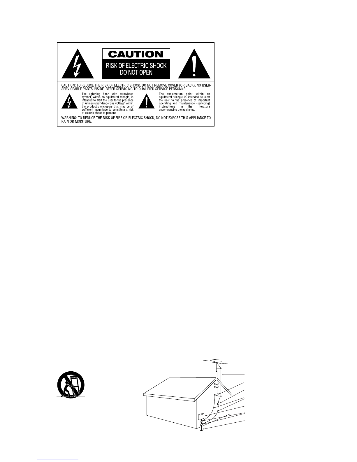
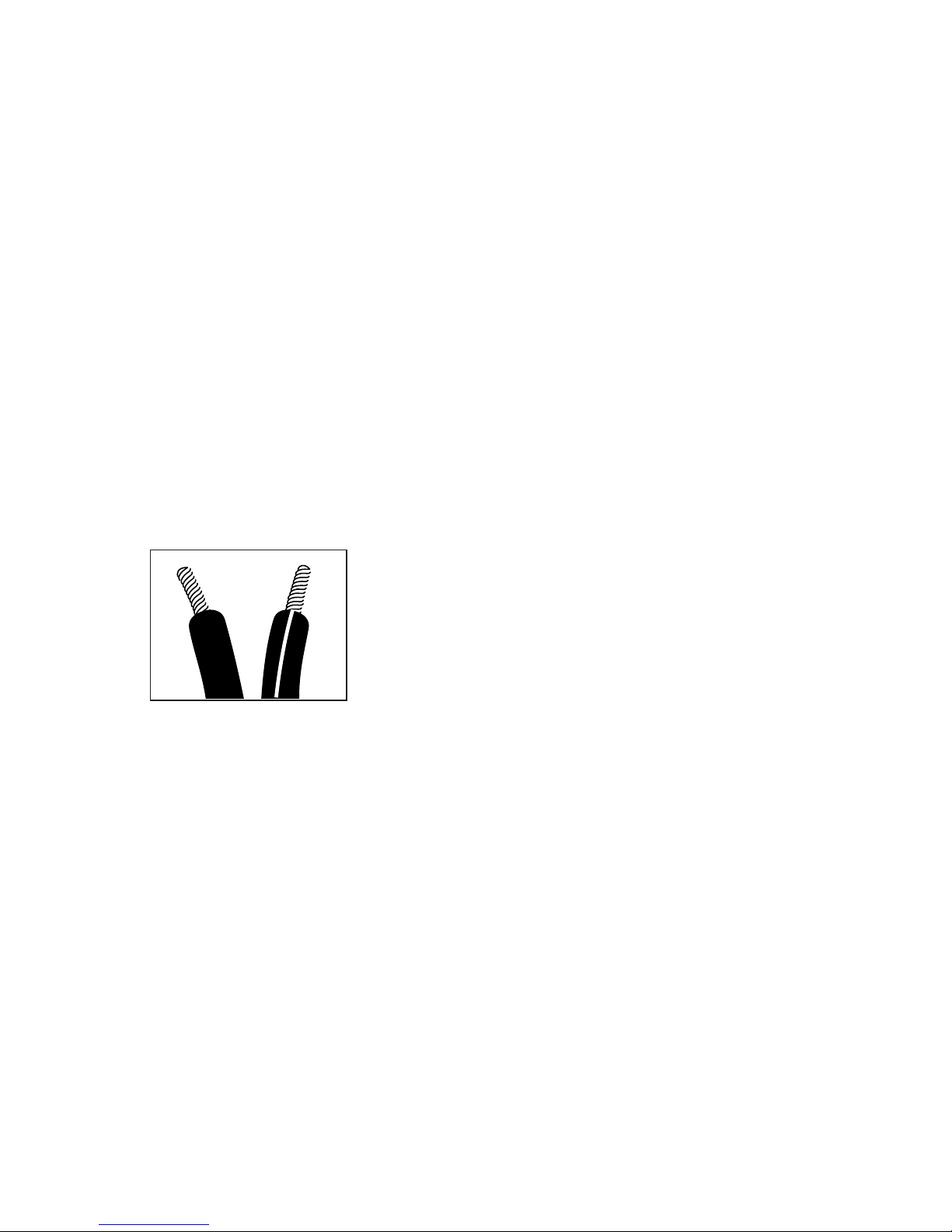
See Figure A.
18. An outside antenna system should
not be located in the vicinity of over-
head power lines or other electric
light or power circuits, or where it
can fall into such power lines or cir-
cuits. When installing an outside
antenna system, extreme care should
be taken to keep from touching such
power lines or circuits, as contact
with them might be fatal.
19. Specifications: All product
specifications/features are subject to
change without notification.
Passive Products:
20. Amplifiers: Amplifiers used to
drive these units must deliver a suffi-
cient output power. A lack of output
power may lead to amplifier-clipping,
which causes damage not covered by
guarantee.
Active (Powered) Products:
21. Ventilation. Slots and openings in
the cabinet are provided for ventila-
tion and to ensure reliable operation
of the product and to protect it from
overheating, and these openings
must not be blocked or covered. The
openings should never be blocked by
placing the product on a bed, sofa,
rug, or other similar surface. This
product should not be placed in a
built-in installation such as a book-
case or rack unless proper ventilation
is provided or the manufacturer’s
instructions have been adhered to.
Make certain that the proper space
(more than 10cm) is provided both
above and below the unit for ventila-
tion. If the amplifier will be installed in
a cabinet or other enclosed area,
make certain that there is sufficient
air movement within the cabinet, with
means provided for hot air to exit and
for cool air to be brought in.
Do not obstruct the ventilation slots
on the top of the unit or place objects
directly over them. Remember, power
amplifiers generate heat, and the
heatsink fins and ventilation slots that
form part of the cabinet are specially
designed to remove this heat. Placing
other electronic equipment near
these heat-dissipation systems may
possibly affect the long term reliabil-
ity of both your amplifier and the
objects placed above it. Do not place
CDs, record jackets, owner’s manuals
or other paper on top of or beneath
the unit or in between products con-
taining amplifiers in a stack. This will
block the air flow, causing degraded
performance and a possible fire haz-
ard.
22. Power Sources. This product
should be operated only from the type
of power source indicated on the
marking label. If you are not sure of
the type of power supply to your
home, consult your product dealer or
local power company. For products
intended to operate from battery
power, or other sources, refer to the
operating instructions.
23. Grounding or Polarization. This
product may be equipped with a polar-
ized alternating-current line plug (a
plug having one blade wider than the
other). This plug will fit into the power
outlet only one way. This is a safety
feature. If you are unable to insert the
plug fully into the outlet, try reversing
the plug. If the plug should still fail to
fit, contact your electrician to replace
your obsolete outlet. Do not defeat the
safety purpose of the polarized plug.
24. Power-Cord Protection. Power-
supply cords should be routed so that
they are not likely to be walked on or
pinched by items placed upon or
against them, paying particular atten-
tion to cords at plugs, convenience
receptacles, and the point where
they exit from the product. To avoid
safety hazards, use only the power
cord supplied with your unit. If a
replacement cord is used, make cer-
tain that it is of a similar gauge. We
do not recommend using extension
cords with this product. As with all
electrical devices, do not run power
cords under rugs or carpets or place
heavy objects on power cords. Dam-
aged power cords should be replaced
immediately, by a qualified service
technician, with cords meeting fac-
tory specifications. When discon-
necting the power cord from an AC
outlet, always pull the plug; never pull
the cord.
25. Non-use Periods. The power cord
of the product should be unplugged
from the outlet when left unused for
long periods of time.
26. Lightning. For added protection
for this product during a lightning
storm, or when it is left unattended
and unused for long periods of time,
unplug it from the wall outlet and dis-
connect the antenna or cable system.
This will prevent damage to the prod-
uct due to lightning and power-line
surges.
27. Overloading. Do not overload wall
outlets, extension cords, or integral
convenience receptacles, as this can
result in a risk of fire or electric shock.
28. Damage Requiring Service. Do
not attempt to service this product
yourself, as opening or removing cov-
ers may expose you to dangerous
voltage or other hazards. Unplug this
product from the wall outlet and refer
servicing to qualified service person-
nel under the following conditions:
a. The power-supply cord or the plug
has been damaged; or
b. Objects have fallen, or liquid has
been spilled into, the product; or
c. The product has been exposed to
rain or water; or
d. The product does not operate nor-
mally when following the operating
instructions. Adjust only those con-
trols that are covered by the oper-
ating instructions, as an improper
adjustment of other
controls may result in damage and
will often require extensive work by
a qualified technician to restore the
product to its normal operation; or
e. The product has been dropped, or
the enclosure damaged; or
f. The product does not appear to
operate normally or exhibits a
marked change in performance.
29. Object and Liquid Entry. Never
push objects of any kind into this prod-
uct through openings, as they may
touch dangerous voltage points or
short-out parts that could result in a
fire or electric shock. Never spill liquid
of any kind on the product. The appa-
ratus shall not be exposed to dripping
or splashing and no objects filled with
liquids, such as vases, shall be placed
on the apparatus.
30. Heat. The product should be situ-
ated away from heat sources such as
radiators, heat registers, stoves or
other products (including amplifiers)
that produce heat. Avoid installation
in extremely hot or cold locations, in
an area that is exposed to direct sun-
light or near heating equipment.
When positioning the product in its
final location, make certain that it has
adequate ventilation on all sides, as
well as on the top and bottom.

4
INCLUDED
THANK YOU FOR CHOOSING JBL
For more than 55 years, JBL
has been involved in every
aspect of music and film
recording and reproduction,
from live performances to
the recordings you play in
your home, car or office.
We’re confident that the JBL
system you have chosen will
provide every note of enjoy-
ment that you expected –
and that when you think
about purchasing additional
audio equipment for your
home, car or office, you will
once again choose JBL.
Please take a moment to
register your product on our
Web site at www.jbl.com.
It enables us to keep you
posted on our latest advance-
ments, and helps us to better
understand our customers
and build products that
meet their needs and
expectations.
JBL Consumer Products
Five (four in SCS260.5 system)
satellites for left, right and
surrounds. Wall-mount brackets.
Shelf stands.
One center channel speaker with
shelf stand.
Powered subwoofer.
Three 6m (20') speaker cables for con-
nection to front, left, center and right
speakers, or to subwoofer when
speaker-level connections are used
(see page 10).
Two 4.6m (15') speaker cables for con-
nection from subwoofer to front speak-
ers, when speaker-level connections
are used (see page 10).
Three (two in SCS260.5 system) 12m
(40') speaker cables for connection
from receiver to rear satellites.
One 4.6m (15') RCA interconnect cable
for connection from receiver to sub-
woofer’s LFE input.

5
SPEAKER PLACEMENT
SUBWOOFER
SURROUND SPEAKERS
†
1.5 – 1.8m
5 – 6 ft
†
FRONT
SPEAKERS
0-0.6m
(0-2 ft)
The front speakers should be
placed the same distance
from each other as they are
from the listening position.
They should be placed at
about the same height from
the floor as the listeners’
ears will be, or they may be
angled toward the listeners.
The center channel speaker
should be placed slightly
behind the front left and right
speakers, and no more than
two feet above or below the
tweeters of the left and right
speakers. It is often con-
venient to set the center
speaker on top of the tele-
vision set, as shown in the
drawing.
Two of the surround speak-
ers should be placed slightly
behind the listening position
and, ideally, should face
each other and be at a level
higher than the listeners’
ears. If that is not possible,
they may be placed on a wall
behind the listening position,
facing forward. The surround
back speaker (SCS260.6 sys-
tem only) should be placed
on the wall behind the listen-
ing position, facing the cen-
ter channel speaker. The sur-
round speakers should not
call attention to themselves.
Experiment with their place-
ment until you hear a diffuse,
ambient sound accom-
panying the main program
material heard in the front
speakers.
It is neither necessary nor
desirable to tilt the surround
speakers to aim them down
toward the listening area.
They should be aimed
straight ahead to produce
the proper effect.
The low-frequency material
reproduced by the sub-
woofer is mostly omnidirec-
tional, and this speaker may
be placed in a convenient
location in the room. How-
ever, bass reproduction will
be maximized when the sub-
woofer is placed in a corner
along the same wall as the
front speakers. Experiment
with subwoofer placement
by temporarily placing the
subwoofer in the listening
position and moving around
the room until the bass
reproduction is best. Place
the subwoofer in that loca-
tion.
CENTER CHANNEL
SPEAKER
Alternate placement for surround speakers in SCS260.5
system only.
†Surround back speaker is used
only in SCS260.6 system.

6
MOUNTING OPTIONS
On shelves. On the wall.
Wall brackets are included.
On optional stands.
SATELLITES AND SURROUNDS
Prepare the speaker wire as
described on page 8. Thread
the two conductors through
the two holes in the stand
bracket. Make sure to pre-
serve the proper polarity
(+ and – connections) by
threading the positive con-
ductor through the hole on
the left, and the negative
conductor through the hole
on the right looking at the
front of the stand. Push
down on the red speaker ter-
minal and insert the bare end
of the positive wire into the
hole under the red cap.
Release the cap, and tug
gently on the wire to make
sure that the connection is
snug. Follow the same pro-
cedure to connect the nega-
tive wire to its terminal.
Use the larger screw in the
upper screw hole, and the
smaller screw in the lower
screw hole.
ATTACHING THE SHELF STAND TO THE SPEAKER
+
–
Gently pull the slack out of
the wire and screw the shelf
stand onto the back of the
speaker in two places, as
shown.

7
Important Safety Note: The
customer is solely responsi-
ble for proper selection of
mounting hardware not
included with the speakers,
and for proper assembly and
installation of the wall-brack-
ets, including but not limited
to the selection of appropri-
ate weight-bearing supports
and proper use of the
bracket. JBL disclaims any
liability for the selection of
mounting hardware and/or
bracket installation. Be sure
to follow these bracket
assembly and installation
instructions carefully. If you
have any questions or
doubts about your ability to
correctly wall-mount the
speakers, consult with your
authorized JBL dealer or
custom installer.
Step 1: Unscrew and remove
the large Molded Nut
™
. If
necessary, use the supplied
Metal Bar
∞
as a lever by
inserting it into one of the
holes in the outer edge of the
Molded Nut
™
.
Step 2: Firmly grasp the Ball
and Shaft
£
and pull it
straight out of the Attach-
ment Plate
¢
. Avoid leaning
it to the side for leverage, as
this may break off a tab.
Step 3: Slide the Molded Nut
™
onto the Ball and Shaft
£
with the threaded open-
ing facing the ball. Thread
the Metal Nut ¡all the way
onto the Ball and Shaft £,
with the star washer side
away from the ball. Refer to
the exploded drawing for the
proper orientation of these
three parts.
Step 4: Screw the Ball and
Shaft
£
into the Threaded
Insert
§
on the back of the
Satellite Speaker
¶
until it
is fully seated in the
Threaded Insert
§
, but do
not tighten as you might dis-
lodge the Threaded Insert
§. Such damage would
not be covered under the
warranty.
Step 5: Tighten the Metal Nut
¡
with the star washer side
between the Metal Nut
¡
and the back of the Satellite
Speaker
¶
, using large
needle-nose pliers until it is
firmly seated against the
back of the Speaker
¶
and
has locked the Ball and
Shaft
£
and the Speaker
¶
together.
Note that once the Metal
Nut
¡
is fully tightened, it
may embed some marks on
the back of the Satellite
Speaker
¶
. However, these
marks will be covered by the
Metal Nut
¡
.
Step 6: Mount the Attach-
ment Plate
¢
into a wood
stud on the wall, using four
#10 pan-head wood screws
at least one inch long (not
supplied)
•
. Make sure that
all four screws are driven
into the stud and not into dry-
wall. If the bracket needs to
be mounted in drywall, the
customer is responsible for
selecting and using appro-
priate wall-anchors and
screws.
Important Note: The Metal
Nut
¡
must be fully tight-
ened against the Satellite
Speaker
¶
as described in
WALL-MOUNTING
1
2
3
4
8
5
12
34
5
6
7
8

CONNECTION TIPS
SPEAKER CONNECTIONS
Separate and strip the ends
of the speaker wire as
shown. The wires supplied
with the system may already
be stripped and tinned for
easy insertion into the
speaker terminals. You may
need to separate the two
conductors further in order
to thread them through the
shelf stand or floor stand
adaptor. Speakers and elec-
tronics terminals have corre-
sponding (+) and (–) termi-
nals. Most manufacturers of
speakers and electronics,
including JBL, use red to
denote the (+) terminal and
black to denote the (–)
terminal.
The (+) lead of the speaker
wire is noted with a stripe. It
is important to connect both
speakers identically: (+) on
the speaker to (+) on the
amplifier and (–) on the
speaker to (–) on the ampli-
fier. Wiring “out of phase”
results in thin sound, weak
bass and a poor stereo
image.
With the advent of multi-
channel surround sound
systems, connecting all of
the speakers in your system
with the correct polarity
remains equally important in
order to preserve the proper
ambience and directionality
of the program material.
To connect the supplied
speaker wires to the satellite
and center speaker termi-
nals, press the red or black
plastic cap for the desired
terminal, insert the bare end
of the wire into the hole
below the cap and release
the cap.
Gently tug on the wire to
make sure that it is fully
inserted.
To use the binding-post
speaker terminals on the
subwoofer, unscrew the
colored collar until the pass-
through hole in the center
post is visible under the
collar. Insert the bare end of
the wire through this hole;
then screw the collar down
until the connection is tight.
The hole in the center of
each collar is intended for
use with banana-type con-
nectors. To comply with
European CE certification,
these holes are blocked with
plastic inserts at the point of
manufacture. To use banana-
type connectors requires the
removal of the inserts. Do not
remove these inserts if you
are using the product in an
area covered by the Euro-
pean CE certification.
Step 5 before beginning Step
7 in order to avoid damage to
the Threaded Insert
§
.
Such damage would not be
covered under the warranty.
Step 7: Holding the Satellite
Speaker
¶
with both hands,
reinsert the ball portion of
the Ball and Shaft
£
into the
Attachment Plate
¢
.
Step 8: Hand-tighten the
Molded Nut
™
while posi-
tioning the speaker for the
desired orientation. If the
Molded Nut
™
is difficult to
tighten by hand, insert the
Metal Bar
∞
into one of the
holes in the outer edge of the
Molded Nut
™
and use the
bar as a lever. Be careful not
to cross-thread.
The swiveling ball enables
you to aim the speaker to one
side or the other, or to tilt it
up or down. Although stereo
imaging may be improved by
aiming the front speakers
toward the listening position,
especially for music selec-
tions, the surround speakers
are intended to provide a dif-
fuse, ambient sound that is
best achieved by aiming the
speakers straight out from
the wall. Aiming the surround
speakers toward the listen-
ing position may ruin the
intended effect by calling too
much attention to the infor-
mation in those channels.
Step 9: Once the speaker’s
orientation has been final-
ized, insert the Metal Bar
∞
into one of the holes in the
outer edge of the Molded
Nut
™
and tighten the
Molded Nut
™
securely.
Keep the Metal Bar
∞
in a
safe place in the event that
you decide to adjust the
speaker’s orientation in the
future.
8

9
DOLBY PRO LOGIC* (NON-DIGITAL)
–
LINE LEVEL
Use this installation method
for Dolby Pro Logic* applica-
tions (not Dolby Digital, DTS
or other digital processing),
where the receiver/proces-
sor is equipped with a sub-
woofer output, or a volume-
controlled preamp (line-)
level output:
Use RCA-type interconnects
to connect the line-level
subwoofer outputs on your
receiver or amplifier to the
line-level inputs on the sub-
woofer. IMPORTANT: Do not
use the LFE input on the sub-
woofer with Dolby Pro Logic
processors.
NOTE: If your receiver or
amplifier only has one sub-
woofer output jack, then you
will need to use a Y-connec-
tor (not included). Plug the
male end of the Y-connector
into your receiver or ampli-
fier’s subwoofer output jack,
and connect each of the two
female ends to separate
RCA-type interconnects.
Finally, plug the RCA-type
interconnects into the line-
level inputs on the sub-
woofer.
Connect each speaker to
the corresponding speaker
terminals on your receiver
or amplifier.
Make sure your receiver or
processor is correctly con-
figured to indicate that the
subwoofer is “On.”
Note for advanced users: If
your receiver/processor has
a built-in low-pass crossover
filter for the subwoofer out-
put, you may use the LFE
input to bypass the sub-
woofer’s internal crossover.
Use this installation method
for Dolby* Digital, DTS®or
other digital surround
processors:
Use the line-level input jack
marked “LFE” for the Low-
Frequency Effects channel.
Connect this jack to the LFE
output or subwoofer output
on your receiver or amplifier.
Connect each speaker to the
corresponding speaker
terminals on your receiver
or amplifier.
Make sure that you have
configured your surround
sound processor for “Sub-
woofer On”.
For the SCS260.6 system, the
receiver should be config-
ured for 6.1-channel opera-
tion. For both the SCS260.5
and SCS260.6 systems, the
front left, front right, center
and rear speakers should all
be set to “Small.”
If your receiver allows you to
set the crossover frequency
between the subwoofer and
the main speakers, select
120Hz or the setting that is
the closest frequency below
it.
DOLBY* DIGITAL OR DTS®
(OR OTHER DIGITAL SURROUND MODE) CONNECTION
LINE
LEVEL
IN
LFE L R
LFE OUT
SUBWOOFER
RECEIVER
– +
– +
– +
– +
– +
– +
– +
– +– +
Receiver
Subwoofer
Out
Left
Front
Left
Surround – +
Ri ht
Front
Ri ht
Surround
Subwoofer
R L
Center
Surround Back
†
Line-
Level In
Ri ht Surround
Ri ht Front
Left Surround
Left Front Center
R
L
– +
Surround Back†
– +

10
DOLBY PRO LOGIC (NON-DIGITAL) – SPEAKER LEVEL
Use this installation method
for Dolby Pro Logic applica-
tions (not Dolby Digital, DTS
or other digital processing),
where the receiver/proces-
sor does not have a sub-
woofer output, or a volume-
controlled preamp (line-)
level output:
Connect your receiver or
amplifier’s front left and right
speaker terminals to the left
and right terminals on the
subwoofer that are marked
“Speaker Level In.” Connect
the left and right terminals
on the subwoofer that are
marked “Speaker Level Out”
to the corresponding termi-
nals on the back of your front
left and right speakers.
Connect your receiver or
amplifier’s center, surround
and surround back speaker
terminals to the correspon-
ding terminals on the back of
your center and surround
speakers.
Ri ht Front
Ri ht Surround
Left Front
Left Surround
Center
– + – +
– +
– + – +
– +
– +
– + – + – +
Left Front Center
Left Surround
Ri ht Front
Ri ht Surround
Surround Back†
Surround Back
†
Subwoofer
Receiver
S
P
E
A
K
E
R
L
E
V
E
L
R
L
R
L
OUT IN
+
–
–
+
+
–
–
+
– + – +
†Surround back speaker is used only in SCS260.6 system.

11
OPERATION
MIN MAX
Subwoofer
Level
MIN MAX
Subwoofer
Level
Move the Master Power
switch (marked “Power”
å
)
to the “•” (On) position to use
the SUB260 subwoofer.
If you will be away from
home for an extended period
of time, or if the subwoofer
will not be used, switch the
Master Power switch
å
to
the Off position.
VOLUME
∫
å
Volume may be adjusted
using the Subwoofer Level
control
∫
as shown.

12
If there is no sound from any
of the speakers:
• Check that receiver/ampli-
fier is on and a source is
playing.
• Check that the powered
subwoofer is plugged in,
and its
Power switch
å
is
switched on (“•” position).
• Check all wires and con-
nections between receiver/
amplifier and speakers.
Make sure all wires are
connected. Make sure
none of the speaker wires
are frayed, cut or punc-
tured, or touching each
other.
• Review proper operation of
your receiver/amplifier.
If there is no sound coming
from one speaker:
• Check the “Balance” control
on your receiver/amplifier.
• Check all wires and con-
nections between receiver/
amplifier and speakers.
Make sure all wires are
connected. Make sure
none of the speaker wires
are frayed, cut or punc-
tured, or touching each
other.
• In Dolby Digital or DTS
modes, make sure that the
receiver/processor is con-
figured so that the speaker
in question is enabled.
• Turn off all electronics
and switch the speaker in
question with one of the
other speakers that is
working correctly. Turn
everything back on, and
determine whether the
problem has followed the
speaker, or has remained in
the same channel. If the
problem is in the same
channel, the source of the
problem is most likely with
your receiver or amplifier,
and you should consult the
owner’s manual for that
product for further informa-
tion. If the problem has fol-
lowed the speaker, consult
your dealer for further
assistance or, if that is not
possible, visit
www.jbl.com.
If there is no sound from the
center speaker:
• Check all wires and con-
nections between receiver/
amplifier and speaker.
Make sure all wires are
connected. Make sure
none of the speaker wires
are frayed, cut or punc-
tured, or touching each
other.
• If your receiver/processor
is set in Dolby Pro Logic
mode, make sure the center
speaker is not in phantom
mode.
• If your receiver/processor
is set in one of the Dolby
Digital or DTS
modes, make
sure the receiver/
processor
is configured so that the
center speaker is enabled.
If the system plays at low
volumes but shuts off as
volume is increased:
• Check all wires and con-
nections between receiver/
amplifier and speakers.
Make sure all wires are
connected. Make sure
none of the speaker wires
are frayed, cut or punc-
tured, or touching each
other.
• If more than one pair of
main speakers is being
used, check the minimum
impedance requirements of
your receiver/amplifier.
If there is low (or no) bass
output:
• Make sure the connections
to the left and right
“Speaker Inputs” have the
correct polarity (+ and –).
• Make sure the subwoofer
is plugged into an active
electrical outlet
, and is
turned on (Power switch
å
in the “•” position).
• In Dolby Digital or DTS
modes, make sure your
receiver/processor is con-
figured so that the sub-
woofer and LFE output are
enabled.
TROUBLESHOOTING

13
If there is no sound from
the surround speakers:
• Check all wires and con-
nections between receiver/
amplifier and speakers.
Make sure all wires are
connected. Make sure
none of the speaker wires
are frayed, cut or punc-
tured, or touching each
other.
• Review proper operation of
your receiver/amplifier and
its surround sound fea-
tures.
• Make sure the movie or
TV show you are watching
is recorded in a surround
sound mode. If it is not,
check to see whether your
receiver/amplifier has other
surround modes you may
use.
•
In Dolby Digital or DTS
modes, make sure your
receiver/processor is con-
figured so that the surround
speakers are enabled.
When all five satellites are
in use, remember to config-
ure your receiver or proces-
sor for 6.1-channel opera-
tion.
• Review the operation of
your DVD player and the
jacket of your DVD to make
sure that the DVD features
the desired Dolby Digital or
DTS mode, and that you
have properly selected that
mode using both the DVD
player’s menu and the DVD
disc’s menu.

14
SCS260.5/230 AND
SCS260.6/230 SYSTEMS
Frequency Response 35Hz – 20kHz (–6dB)
SATELLITES
Maximum Recommended Amplifier Power
100 Watts
Power Handling (Continuous/Peak)
50W/200W
Nominal Impedance 8 Ohms
Sensitivity 88dB @ 1 Watt/1 meter
Frequency Response 100Hz – 20kHz (–6dB)
Tweeter
One 13mm (1/2") titanium-laminate dome,
video-shielded
Midrange
Dual 75mm (3") drivers, video-shielded
Dimensions (H x W x D) (not including shelf
stands) 292 x 102 x 89mm (11-1/2" x 4" x 3-1/2")
Weight 1.4kg (3 lb)
CENTER
Maximum Recommended Amplifier Power
100 Watts
Power Handling (Continuous/Peak)
50W/200W
Nominal Impedance 8 Ohms
Sensitivity 88dB @ 1 Watt/1 meter
Frequency Response 100Hz – 20kHz (–6dB)
Tweeter
One 13mm (1/2") titanium-laminate dome,
video-shielded
Midrange
Dual 75mm (3") drivers, video-shielded
Dimensions (H x W x D) (not including shelf
stand) 102 x 292 x 89mm (4" x 11-1/2" x 3-1/2")
Weight 1.4kg (3 lb)
SUBWOOFER
Amplifier 100 Watts RMS
Frequency Response 35Hz – 160Hz (–6dB)
Woofer 200mm (8")
Enclosure Bass reflex
Dimensions (H x W x D) (including feet)
413 x 279 x 349mm (16-1/4" x 11" x 13-3/4")
Weight 12.7kg (28 lb)
All features and specifications are subject to change
without notice.
*Trademarks of Dolby Laboratories.
DTS is a registered trademark of Digital Theater Systems, Inc.
SPECIFICATIONS
DESIGN GOAL: Bring the thrill of live performance and movie sound
to
the home environment by calling on JBL’s professional engineering leadership.
SATELLITE TYPE:
Titanium-laminate-dome tweeter,
sealed enclosure
SUBWOOFER TYPE:
Bass-reflex enclosure
PORT DESIGN: FreeFlow™flared
PROFESSIONAL REFERENCE:Cinema Loudspeaker Series
OWNER’S GUIDE
PRODUCT LINE:
MODEL:
SCS260.5/230 and SCS260.6/230
SURROUND CINEMA
SPEAKERS
© 2004 Harman International Industries, Incorporated
JBL is a registered trademark of
Harman International Industries, Incorporated.
Part No.
406-000-00960
PRO SOUND
COMES HOME™
JBL Consumer Products
250 Crossways Park Drive, Woodbury, NY 11797
Europe: 2. Route de Tours, 72500 Château du Loir, France
www.jbl.com
Declaration of Conformity
We, Harman Consumer Group International
2, route de Tours
72500 Chateau-du-Loir
France
declare in own responsibility that the products described in this
owner’s manual are in compliance with technical standards:
EN 61000-6-3:2001
EN 61000-6-1:2001
EN 55013:2001
EN 55020:2002
EN 61000-3-2:2000
EN 61000-3-3:1995+A1:2001
EN 60065:2002
Gary Mardell
Harman Consumer Group International
Chateau-du-Loir, France 05/04
This manual suits for next models
3
Table of contents
Other JBL Speakers System manuals

JBL
JBL DSC 500 User manual

JBL
JBL Project EVEREST DD66000 User manual

JBL
JBL Speaker System User manual

JBL
JBL Studio 570 User manual

JBL
JBL Project K2.S5500 User manual

JBL
JBL Bar 5.1 Surround User manual

JBL
JBL Ranger Paragon User manual

JBL
JBL Project EVEREST DD66000 User manual

JBL
JBL Vertec VT4888DP Specification sheet

JBL
JBL DUET 200 User manual