Page 3
GENERAL AMPLIFICATION NOTES & REQUIREMENTS
oFor the purpose of this discussion: Crown I_TECH series amplifiers are used below. HF
indicates High Frequency drivers, MF indicates Mid Frequency drivers, LF indicates Low
Frequency drivers and VLF stands for Very Low Frequency drivers (subwoofers).
oEquivalent amplifiers can be used as substitutions.
oUsers should observe differences in input sensitivity and maximum available power at a given
impedance load.
oUsers may choose to use the same size amplifier to power all components / passbands.
oDSP crossover presets provided by JBL assume that the same amplifier models with equal
voltage gain, are used for each bandpass.
oIf different gain settings or amplifiers models are used, users may need to adjust the output
gains of the digital controller(s).
VT4489
o 4 VT4889 can be powered with (4) I-T4000.
Two boxes are wired in parallel per NL8 circuit.
(HF: CH1 & CH2, MF: CH1 & CH2, LO1: CH1 & CH2, LO2: CH1 & CH2)
o Using (4) I-T6000 would provide enough power to drive up to 6 VT4889.
Three boxes are wired in parallel per NL8 circuit.
o I-T4000 can be used for the HF section to power 2 or 3 boxes.
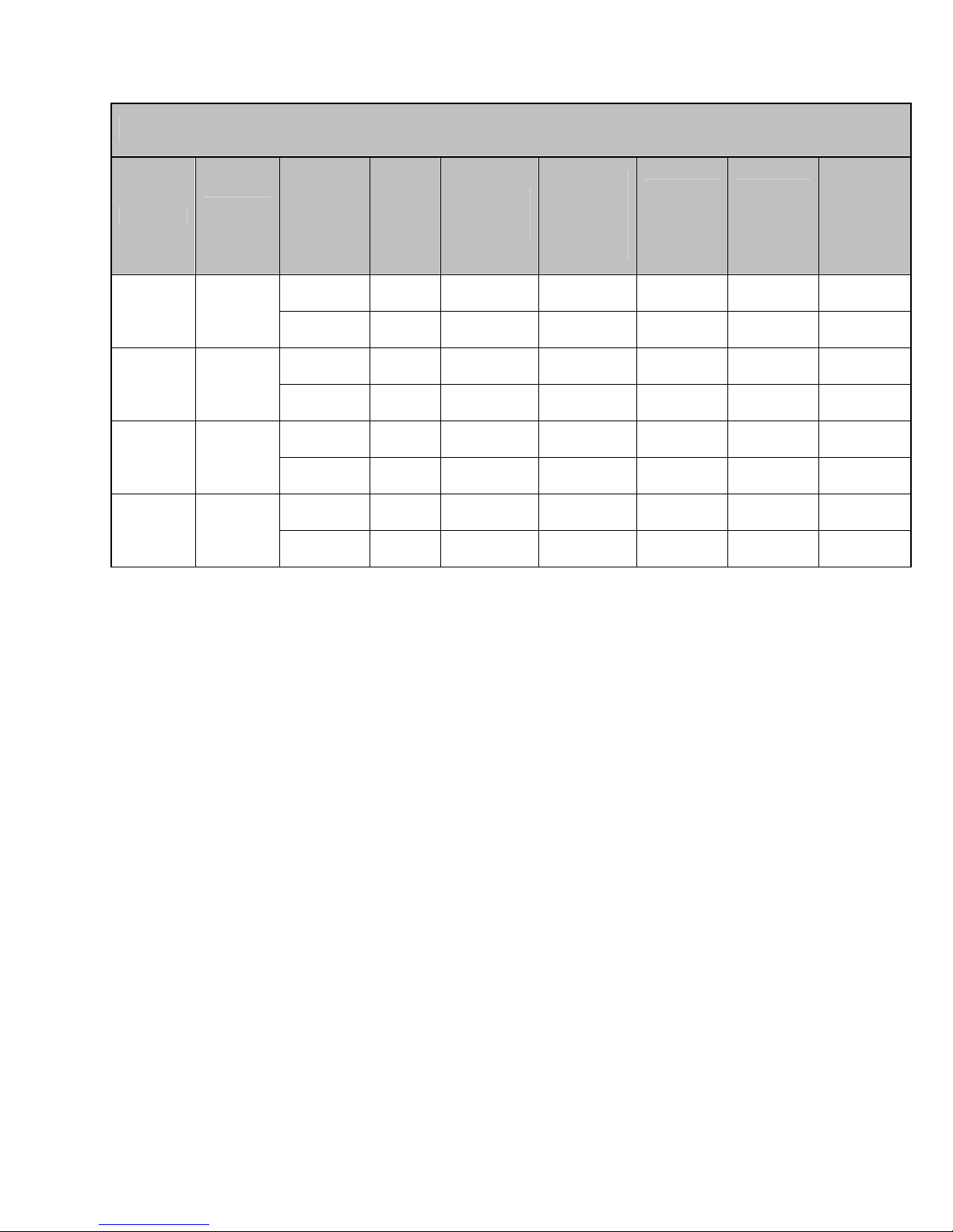
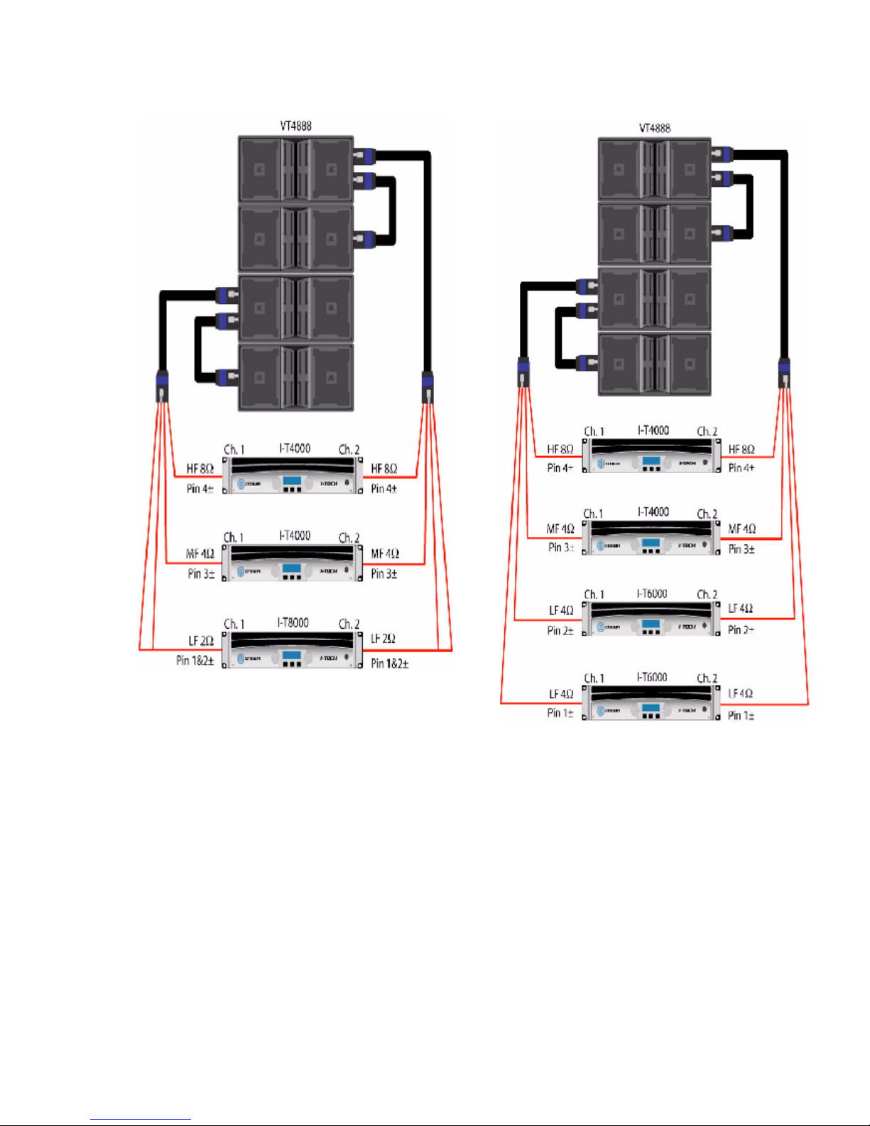
VT4888
o 4 VT4888 can be powered with 4 I-T4000.
Two boxes are wired in parallel per NL8 circuit.
(HF: CH1 & CH2, MF: CH1 & CH2, LO1: CH1 & CH2, LO2: CH1 & CH2)
o Using 4 I-T6000 would provide enough power to drive up to 6 VT4888.
Three boxes are wired in parallel.
o I-T4000 can be used for the HF or MF section to power 2 or 3 boxes.
VT 4887
o 4 VT4887 can be powered with (1) I-T4000.
If four boxes are wired in parallel per NL8 circuit then
CH1: LF @ 2 ohms & CH2: MH/HF @ 2 ohms.
VT4880
o 2 VT4880 can be powered with (1) I-T4000.
If two boxes are wired in parallel using NL4 cables then each amp channel powers (4) 2258
for a 4 ohms load.
o 3 VT4880 can be powered with (1) I-T6000.
If three boxes are wired in parallel using NL4 cables then each amp channel powers (3)
2258 for a 2.7 ohms load.
o 4 VT4880 can be powered with (1) I-T8000.
If four boxes are wired in parallel using NL4 cables then each amp channel powers (4) 2258
for a 2.0 ohms load.
Separate NL4 cable runs are recommended with parallel wiring at the amp.
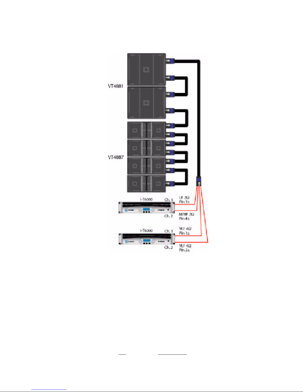
VT4881
o 4 VT4881 can be powered with (1) I-T4000.
If four boxes are wired in parallel using NL4 cables then each amp channel powers (4)
distinct coils of dual-coil 2256Gs for a 2.0 ohms load. Each 2256G has (2) coils.
Separate NL4 cable runs are recommended with parallel wiring at the amp.