E Oi.324
6
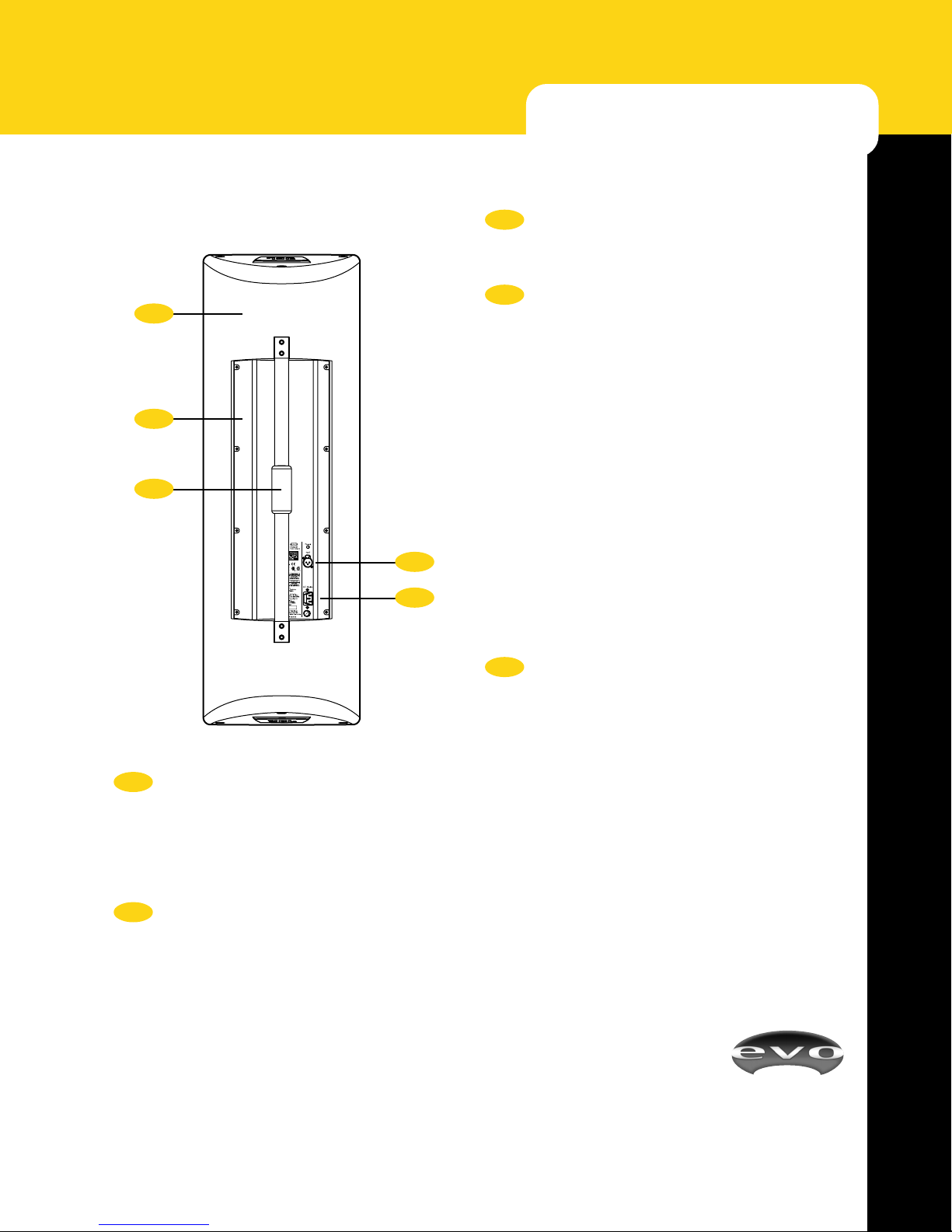
Input
Power
AC Main
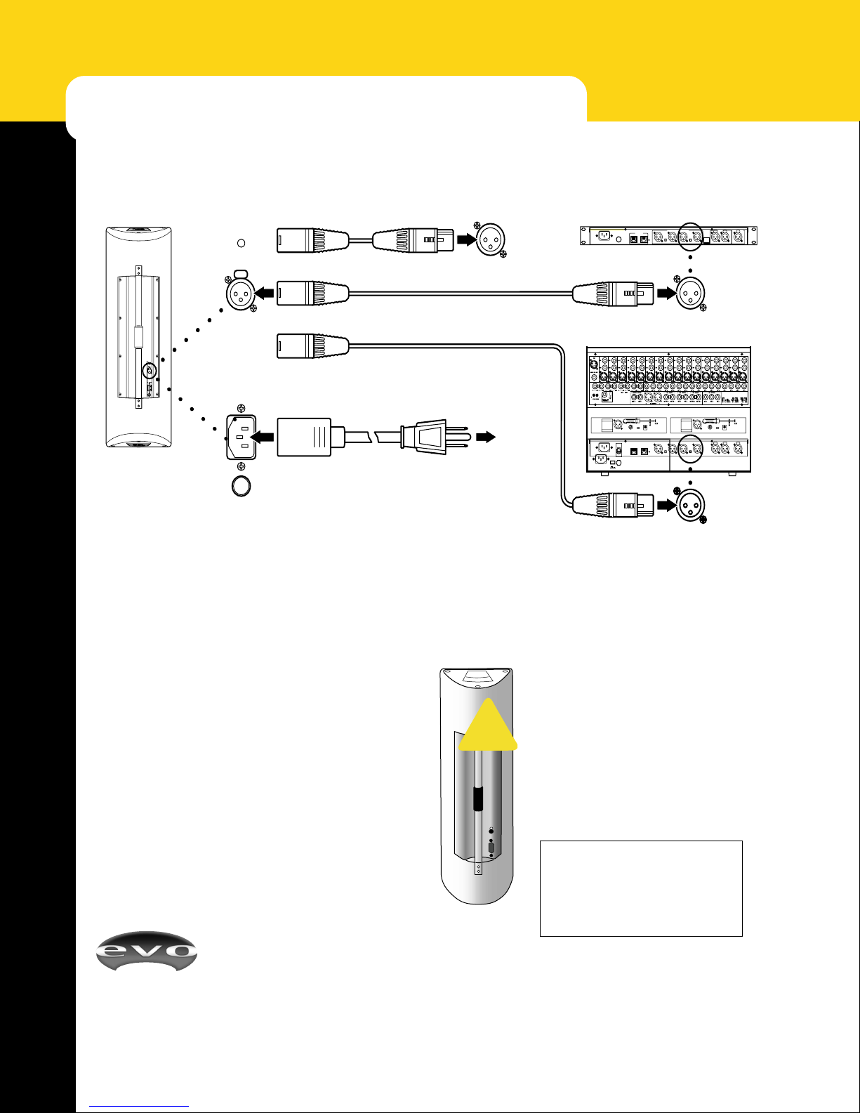
HOOK-UP DETAILS
AUDIO AND AC POWER CONNECTIONS
Power Cycle (Boot-up) Times
EVOi.324’s internal DSP (Digital Signal Processor) circuit
board includes software applications. Like any device
operating software programs, there is a “boot-up” time lag
before EVOi.324 becomes fully operational. The audio
signal will be muted until the loudspeaker is fully
booted up. This should take approximately 20 seconds.
Upon connecting AC mains, the green
power indicator will illuminate. After
approximately 20 seconds there will be a
very quiet click as the system releases the
mute. Upon power disconnection, the
green power indicator will flash several
times, however signal shut-down is
instantaneous. In summary, boot-up time
is approximately 20 seconds and shut-
down time is 0 seconds.
WARNING! When EVOi.324 is on,
the amplifier heatsink will get hot
even when no signal is being passed.
This is normal operation for D-Class
amplifiers.
E Oi.324 Rear
OR
OR
Output on Generic Mixer E Oi.net Rear
E Oi.sys Rear
XLR Signal Cable
Power Cord (supplied)
AC Mains
Maximum Drive Level = +10 dBu * Sensitivity
There are three simple audio hook-up options: all require
the use of high quality balanced signal cable with a Male
XLR connector. EVOi.324 requires a drive level of +10
dBu (sensitivity = +10 dBu assuming no external equaliza-
tion has been applied to the signal) for maximum perfor-
mance. Hooking a microphone directly to the input will
NOT drive it sufficiently. The output of a standard mixer,
EVOi.net or EVOi.sys should provide the optimum drive
level. (See the Sensitivity Chart in the Appendix, page 21)
Power Requirements
IMPORTANT: Each individual EVOi.324 is an extremely
powerful system and is quite capable of drawing peak
currents of up to 18 amps. Please consult a qualified
electrician for correct installation and power connection.
For more information, see AC Requirements on page 21.
CAUTION: to reduce the risk of fire, replace fuse with
same type and rating: ATTENTION: utiliser un fusible de
rechange de meme type de:
115V~ T6.3A/250V~
230V~ T3.15A/250V~
Sensitivity (direct in) +10 dBu
assuming no EQ has been applied.
!
* 0 dBu = 0.775 Volts; +10 dBu = 2.45 Volts
Fuse
Figure 3 - Basic E Oi.324 Audio and AC Connections