JBL VP7215 Specification sheet

DrivePack® DPC-2
Product User’s Guide
VP7215/95DPC VP7210/95DP VP7212MDP VP7212/95DPC

2Venue Performance Series User’s Guide

3
JBL Professional
Section 1. Safety Instructions .....................................................................................Page 4
Section 2. Before You Begin .......................................................................................Page 7
Section 3. Introduction to VP Series Powered Loudspeaker Systems ..................Page 8
Specifications by model
Section 4. VP Series Transducers ..............................................................................Page 10
Section 5. Enclosure Care and Maintenance ............................................................Page 11
Section 6. Suspension Hardware ...............................................................................Page 12
Safety Precautions
Industry Resources
Section 7. JBL DrivePack® Technology .....................................................................Page 15
AC Power Module, Electrical Information
Section 8. Input Panel Information .............................................................................Page 19
Section 9. JBL Professional Warranty .......................................................................Page 24
Section 10. Factory Contact Information ....................................................................Page 25
TABLE OF CONTENTS

4Venue Performance Series User’s Guide
SECTION 1 : SAFETY INSTRUCTIONS
Important
1. Read these instructions.
2. Keep these instructions.
3. Heed all warnings.
4. Follow all instructions.
5. Do not use this apparatus near water.
6. Clean only with dry cloth.
7. Do not block any ventilation openings. Install in accordance with the manufacturer’s instructions.
8. Do not install near any heat sources such as radiators, heat registers, stoves, or other apparatus
(including amplifiers) that produce heat.
9. Do not defeat the safety purpose of the polarized or grounding-type plug. A polarized plug has
two blades with one wider than the other. A grounding-type plug has two blades and a third
grounding prong. The wide blade or the third prong are provided for your safety. If the provided
plug does not fit into your outlet, consult an electrician for replacement of the obsolete outlet.
10. Protect the power cord from being walked on or pinched, particularly at plugs, convenience
receptacles, and the point where they exit from the apparatus.
11. Only use attachments/accessories specified by the manufacturer.
12. Use only with the cart, stand, tripod, bracket, or table specified by the manufacturer, or
sold with the apparatus. When a cart is used, use caution when moving the cart/apparatus
combination to avoid injury from tip-over.
13. Unplug this apparatus during lightning storms or when unused for long periods of time.
14. Refer all servicing to qualified service personnel. Servicing is required when the apparatus has
been damaged in any way, such as power supply cord or plug is damaged, liquid has been
spilled or objects have fallen into the apparatus, the apparatus has been exposed to rain or
moisture, does not operate normally, or has been dropped.
15. WARNING: To reduce the risk of fire or electric shock, do not expose this apparatus
to rain or moisture.
16. Do not expose this equipment to dripping or splashing and ensure that no objects filled with
liquids, such as vases, are placed on the equipment.
17. To completely disconnect this apparatus from the AC Mains, disconnect the power supply cord
plug from the AC receptacle.
18. The mains plug of the power supply cord shall remain readily operable.

5
JBL Professional
THIS APPARATUS CONTAINS POTENTIALLY LETHAL VOLTAGES. TO PREVENT ELECTRIC
SHOCK OR HAZARD, DO NOT REMOVE DRIVEPACK CHASSIS, INPUT MODULE OR AC INPUT
COVERS. NO USER SERVICEABLE PARTS INSIDE. REFER SERVICING TO QUALIFIED SERVICE
PERSONNEL.
WATCH FOR THESE SYMBOLS
The lightning bolt triangle is used to alert the user to the risk of electric shock.
The exclamation point triangle is used to alert the user to important operating or
maintenance instructions.
FCC COMPLIANCE NOTICE
This device complies with part 15 of the FCC rules. Operation is subject to the following two condi-
tions: (1) This device may not cause harmful interference, and (2) this device must accept any interfer-
ence received, including interference that may cause undesired operation.
CAUTION: Changes or modifications not expressly approved by the party responsible for compli-
ance could void the user’s authority to operate the equipment.
CSA COMPLIANCE NOTICE
CSA Certification Applies to Amplifier Module Only

6Venue Performance Series User’s Guide
JBL DRIVEPACK® DECLARATION OF CONFORMITY
Safety and EMC Compliance Specifications
EN 55103-1:1997 Electromagnetic Compatibility - Product Family Standard for Audio, Video, Audio-
Visual and Entertainment Lighting Control Apparatus for Professional Use, Part 1: Emissions
EN 55103-1:1997 Magnetic Field Emissions-Annex A @ 10 cm and 1 M
EN 55022:2003 Limits and Methods of Measurement of Radio Disturbance Characteristics of ITE:
Radiated, Class B Limits; Conducted, Class A
EN 55103-2:1997 Electromagnetic Compatibility - Product Family Standard for Audio, Video, Audio-
Visual and Entertainment Lighting Control Apparatus for Professional Use, Part 2: Immunity
EN 61000-4-2: A2:2001 Electrostatic Discharge Immunity (Environment E2-criteria B, 4 kV Contact,
8 kV Air discharge)
EN 61000-4-3:2003 Radiated, Radio-frequency, Electromagnetic Immunity (Environment E2, criteria
A)
EN61000-4-4:2005 Electrical Fast Transient/Burst Immunity (criteria B)
EN 61000-4-5:2001 Surge Immunity (criteria B)
EN 61000-4-6:1996 Immunity to Conducted Disturbances Induced by Radio-Frequency Fields
(criteria A)
EN 61000-4-11:2004 Voltage Dips, Short Interruptions and Voltage Variation
UL 6500 2nd Edition 1999 Audio/Video and Musical Instrument Apparatus for Household,
Commercial and Similar General Use
CAN/CSA E60065-00 Audio, Video and Similar Electronic Apparatus – Safety Requirements

7
JBL Professional
SECTION 2 : BEFORE YOU BEGIN
The VP Series loudspeakers covered by this manual are not intended for fixed installation in outdoor
or high moisture environments. Moisture can damage the speaker cone and surround and cause
corrosion of electrical contacts and metal parts. Avoid exposing the speakers to direct moisture. Keep
loudspeakers out of extended or intense direct sunlight. The driver suspension will prematurely dry out
and finished surfaces may be degraded by long-term exposure to intense ultra-violet (UV) light.
The VP Series loudspeakers can generate considerable energy. When placed on a slippery surface such
as polished wood or linoleum, the speaker may move due to its acoustical energy output. Precautions
should be taken to assure that the speaker does not fall off a stage or table on which it is placed.
Stand mounting safety precautions
Some VP Series models can be used with an optional stand mount accessory allowing mounting
on tripod stands or on a pole over subwoofers. When using stands or poles, be sure to observe the
following precautions:
Check the stand or pole specification to be certain the device is designed to support the
weight of the speaker. Observe all safety precautions specified by the manufacturer.
Always verify that the stand (or subwoofer / pole) is placed on a flat, level, and stable surface
and be sure to fully extend the legs of tripod type stands. Position the stand so that the legs
do not present a trip hazard.
Route cables so that performers, production crew, and audience will not trip over them and
pull the speaker over.
Inspect the stand (or pole and associated hardware) before each use and do not use equipment
with worn, damaged, or missing parts.
Do not attempt to place more than one VP Series loudspeaker on a stand or pole.
Always be cautious in windy, outdoor conditions. It may be necessary to place additional
weight (i.e. sandbags) on the base of the stand to improve stability. Avoid attaching banners or
similar items to any part of a speaker system. Such attachments could act as a sail and topple
the system.
Unless you are confident that you can handle the weight of the speaker, ask another person
to help you get it onto the tripod stand or pole.
Hearing damage, prolonged exposure to excessive SPL
VP Series loudspeakers are easily capable of generating sound pressure levels (SPL) sufficient to
cause permanent hearing damage to performers, production crew and audience members. Caution
should be taken to avoid prolonged exposure to SPL in excess of 90 dB.
Package Contents
• Product User’s Guide (this document)
• JBL DrivePack® self-powered loudspeaker
• A.C. Power North America/Europe Cord-Set
• Warranty Card

8Venue Performance Series User’s Guide
SECTION 3 : INTRODUCTION TO VP SERIES
POWERED LOUDSPEAKER SYSTEMS
VP (Venue Performance) Series
The VP Series is a family of powered integrated audio loudspeaker systems featuring JBL DrivePack®
amplifier modules, designed in cooperation with Crown International. The JBL DrivePack features cutting-
edge technology such as patented high efficiency Class-I or Class D power amplifier circuitry. Loudspeaker
components include patented JBL Differential Drive® woofers. The full-range models feature the JBL 2452H-
SL large format 1.5” exit compression driver. This high frequency driver is coupled to a JBL Progressive
Transition™ (PT) Waveguide for excellent pattern control, smooth frequency response, and low distortion.
Waveguides can be rotated for either a horizontal or vertical orientation.
This guide covers the following models:
VP7210/95DP - 10” two-way, 90 x 50 degree waveguide with integrated bottom panel pole mount
VP7212MDP - 12” two-way floor monitor with 50 x 90 degree waveguide
VP7212/95DPC - 12” two-way, 90 x 50 degree waveguide with integrated bottom panel pole mount
VP7215/95DPC - 15” two-way, 90 x 50 degree waveguide with integrated bottom panel pole mount

9
JBL Professional
VP SERIES SYSTEMS SPECIFICATIONS
VP7210/95DP VP7212MDP VP7212/95DPC VP7215/95DPC
Specifications:
Frequency Response (+/-3dB): 80 Hz - 20 kHz 60 Hz - 18 kHz 65 Hz - 18 kHz 60 Hz - 18 kHz
Frequency Range (-10dB): 50 Hz - 20 kHz 55 Hz - 20 kHz 55 Hz - 20 kHz 45 Hz - 20 kHz
Coverage Pattern: 90° x 50° rotatable waveguide 50° x 90° rotatable waveguide 90° x 50° rotatable waveguide 90° x 50° rotatable waveguide
Directivity Factor (Q): 10 12.6 12.6 12.6
Directivity Index (DI): 10 dB 11 dB 11 dB 11 dB
Max Peak Output: 132 dB SPL 1m 134 dB SPL 1m 134 dB SPL 1m 135 dB SPL 1m
Transducer Section:
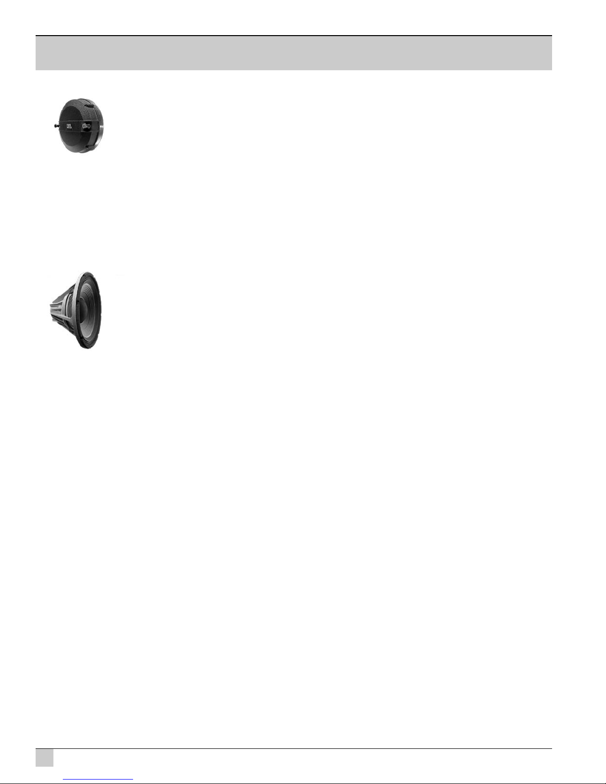
Low Frequency Section: JBL 2261FF, 254 mm (10 in) dia.,
76 mm (3 in) Dual Coil neodymium
Differential Drive®, Direct Cooled
JBL 2262FF, 381 mm (12 in) dia.,
76 mm (3 in) Dual Coil neodymium
Differential Drive®, Direct Cooled
JBL 2262FF, 381 mm (12 in) dia.,
76 mm (3 in) Dual Coil neodymium
Differential Drive®, Direct Cooled
JBL 22625FF, 381 mm (15 in) dia.,
76 mm (3 in) Dual Coil neodymium
Differential Drive®, Direct Cooled
Bandpass Nominal Impedance: 2 x 2 ohms 2 x 2 ohms 2 x 2 ohms 2 x 2 ohms
High Frequency: JBL2452H-SL, 100 mm (4 in)
titanium damped diaphragm, 1.5
in. exit
JBL2452H-SL, 100 mm (4 in)
titanium damped diaphragm, 1.5
in. exit
JBL2452H-SL, 100 mm (4 in)
titanium damped diaphragm, 1.5
in. exit
JBL2452H-SL, 100 mm (4 in)
titanium damped diaphragm, 1.5
in. exit
Bandpass Nominal Impedance: 8 ohms 8 ohms 8 ohms 8 ohms
System:
DPC-2 Internal Amplification
Output
(at nominal load):
1750 Watts Peak (875 Watts Continuous)
DPC-2 Output (Continuous IEC
shaped pink noise into rated load
impedance):
750LF/125HF Watts
DPC-2 Output Section: LF: Dual Bridged Technology™, Class D
HF: Bridged Class D
Audio Input Connector: XLR with loop-through
User Controls: 80 Hz Subwoofer High Pass Filter, Enable/Disable, 0-16 dB input Attenuator with 32 precision 0.5 dB steps
Signal Processing: DSP based, resident in Input Module.
System Management: DSP based limiters for mechanical and thermal protection
AC Power Operating Range: 90-132VAC/216-264VAC, 50/60 Hz
AC Line Voltage: 50/60 Hz, User Select; 120V/240V (-15%, +10%)
AC Input Connector: Neutrik PowerCon (NAC 3MPA)
AC Loop-Thru: Neutrik PowerCon (NAC 3MPB)
AC Current Requirement: 6A per system at 120V, 3A per system at 240V
Enclosure:
Box Construction: 5/8 in. multi-ply exterior grade
Baltic birch. Internally braced.
Black DuraFlex™ finish
5/8 in. multi-ply exterior grade
Baltic birch. Internally braced.
Black DuraFlex™ finish
5/8 in. multi-ply exterior grade
Baltic birch. Internally braced.
Black DuraFlex™ finish
5/8 in. multi-ply exterior grade
Baltic birch. Internally braced.
Black DuraFlex™ finish
Suspension System: 10 M10 fittings, 2 x M6 pullback
on rear, 35 mm standmount None 10 M10 fittings, 2 x M6 pullback on
rear, 35 mm standmount 10 M10 fittings, 2 x M6 pullback on
rear, 35 mm standmount
Grille: 14 Gauge Black, powder-coated perforated steel with foam backing
Dimensions (H x W x D): 521 x 293 x 303 mm
20.5 x 11.5 x 11.9 in. 346 x 565 x 413 mm
13.6 x 22.3 x 16.2 in. 523 x 358 x 334 mm
21.0 x 14.1 x 13.1 in. 613 x 434 x 359 mm
24.1 x 17.1 x 14.1 in.
Net Weight: 18.4 kg (40.5 lbs) 20.7 kg (45.5 lbs) 21.3 kg (47 lbs) 24.7 kg (55 lbs}

10 Venue Performance Series User’s Guide
2452H-SL High Frequency Compression Driver
JBL’s new 2452H-SL features a lightweight neodymium magnet structure, 4” damped laminate diaphragm
and a 1.5” exit. It is designed to deliver crystal-clear sound with superb dynamic range. The 2452H-SL is an
8 Ohm device.
Differential Drive® Low Frequency Drivers
JBL’s patented Differential Drive low frequency drivers dramatically reduces driver weight while greatly
enhancing all critical performance parameters: frequency response, power output, and distortion. The
Differential Drive technology features a unique design with heat sinks integrated into the cast aluminum frame
for a highly improved performance to weight ratio. The dual voice coil design places the neodymium magnets
inside the voice coil assembly, completing the magnetic circuit without the heavy surrounding steel structure
of conventional drivers.
For more information, see JBL Tech Note Vol. 1 Number 33, “Differential Drive Transducers”
SECTION 4: VP SERIES TRANSDUCERS

11
JBL Professional
SECTION 5 : ENCLOSURE CARE AND MAINTENANCE
PAINTING JBL VP SERIES SYSTEM PRODUCTS
VP Series enclosures are constructed of 5/8-in. multi-ply exterior grade Baltic birch. Each enclosure
model is internally braced. The exterior is covered with JBL’s exclusive DuraFlex™ finish.
Each JBL Professional VP Series system model is readily paintable. The DuraFlex finish provides a
lightly textured surface that any household or industrial paint readily adheres to. The result is a speaker
enclosure that is able to blend unobtrusively into the decor of any stage set or environment.
Instructions for painting:
1. Prepare the enclosure surface by cleaning and wiping off dust and film with a damp cloth. It may be
necessary to use a mild household cleaner to remove grease. Avoid using a cloth that will deteriorate
over the textured surface.
2. Apply as many coats of paint as is required. Application can be by rolling, brushing or spraying.
Care must be taken when painting the grille. Avoid any paint or type of application that will clog
the open cells in the foam of the front grille. Depending on the type of paint, it may not be wise to
spray the grille.
3. For painting systems that are installed in environmentally-hostile locations, it is recommended that
an automotive paint should be used for maximum protection.
Note: for systems that will be transported on a regular basis, oil-based paints or Krylon-type spray
paints will give better long-term results than water-based Latex type paints.

12 Venue Performance Series User’s Guide
SECTION 6 : SUSPENSION HARDWARE
Safety Precautions
Before attempting to suspend your speakers, read and understand the following safety information.
IMPORTANT SAFETY WARNING!
The information in this section has been assembled from recognized engineering data and is intended for
informational purposes only. None of the information in this section should be used without first obtaining
competent advice with respect to applicability to a given circumstance. None of the information presented
herein is intended as a representation or warranty on the part of JBL. Anyone making use of this information
assumes all liability arising from such use.
All information presented herein is based upon materials and practices common to North America and may
not directly apply to other countries because of differing material dimensions, specifications, and/or local
regulations. Users in other countries should consult with appropriate engineering and regulatory authorities for
specific guidelines.
Correct use of all hardware is required for secure system suspension. Careful calculations should always be
performed to ensure that all components are used within their rated workload before the array is suspended.
Never exceed maximum recommended load ratings.
Before suspending any speaker system always inspect all components (enclosure, suspension frames, pins,
etc.) for cracks, deformations, corrosion, missing, loose or damaged parts that could reduce strength and
safety of the array. Do not suspend the speaker until the proper corrective action has been taken. Use only
load-rated hardware when suspending VP Series loudspeakers.
Are You New to Rigging?
If you are new to rigging, you should do the following:
• Read and study JBL Technical Note Volume 1, Number 14: Basic Principles for Suspending Loudspeaker
Systems (available at http://www.jblpro.com/pub/technote/tn_v1n14.pdf).
• Know the Rules for Safe Loudspeaker Suspension.
• Attend a safe rigging seminar, such as that presented by professionals like Rigging Seminars™ or by Chain
Motor Hoist manufacturers like Columbus McKinnon Corp. (manufacturers of the C/M Lodestar).
• Meet and establish a relationship with a licensed mechanical or structural engineer. Get in the habit of asking
them questions instead of guessing about their answers. Learn from what they tell you.
• Meet and discuss this aspect of your business with your Insurance Agent.
• Research and understand the codes, practices, and requirements in the venues where you intend to operate
your sound system.

13
JBL Professional
General Hardware Information
Any hardware used in an overhead suspension application must be load rated for the intended use.
Generally, this type of hardware is available from rigging supply houses; industrial supply catalogs and
specialized rigging distributors. Local hardware stores do not usually stock these products.
Attachment to Structures
A licensed Professional Engineer must approve placement and method of attachment to structures
prior to installation of any overhead object. The following performance standards should be provided
to the Professional Engineer for design purposes: Uniform Building Code as applicable, Municipal
Building Code as applicable, Seismic Code as applicable. Installation of hardware and method of
attachment must be carried out in the manner specified by the Professional Engineer. Improper
installation may result in damage, injury or death.
Hardware Inspection & Maintenance
Suspension systems are comprised of mechanical devices and, as such, they require regular
inspection and routine maintenance to insure proper function ability. JBL VP Series loudspeakers
must be inspected for fatigue at least annually. The inspection shall include a visual survey of all
corners and load bearing surfaces for signs of cracking, water damage, de-lamination, or any other
condition that may decrease the strength of the loudspeaker enclosure. Accessory hardware provided
with or for JBL VP Series loudspeakers must be inspected for fatigue at least annually. The inspection
shall include a visual material survey for signs of corrosion, bending or any other condition that may
decrease strength of the fastener. For other fittings used, refer to the manufacturer’s inspection and
maintenance guidelines for process.
JBL is not responsible for the application of its products for any purpose or the misuse of this information
for any purpose. Furthermore, JBL is not responsible for the abuse of its products caused by avoiding
compliance with inspection and maintenance procedures or any other abuse. Prior to suspending the
system, an expert, trained and experienced in flying loudspeaker systems should inspect all suspension
hardware and components.

14 Venue Performance Series User’s Guide
Allen Products / ATM Fly-Ware
(562) 424-1100
1635 E. Burnett Street
Signal Hill, CA 90806
www.allenproducts.com
www.atmflyware.com
M.A.N. Flying Systems
20 Sidar Road Brook Road
Industrial Estate
Rayleight, Essex SS6 7XF U.K.
www.manfly.co.uk
JBL Professional - Tech Note V1 No. 14
“Basic Principles for Suspending Loud-
speakers”
www.jblpro.com/technote/tn_v1n14.pdf
Rigging Seminars
(206) 283-4419
2416 Third Avenue West
Seattle, WA, 98119
www.riggingseminars.com
McMaster Carr
Various locations through the U.S.A.
For a location near you, visit them online:
www.mcmastercarr.com
Safe Suspension Practices
The JBL VP Series suspendable loudspeakers are supplied with built-in brackets. The system is designed to
facilitate the suspension of the loudspeaker by a qualified person familiar with rigging hardware and industry
practices. Improper installation may result in damage, injury or death.
Working Load Limit
The working load limit (WLL) of JBL VP 7210/95DP, VP7212/95DPC and VP7215/95DPC suspendable loud-
speakers shall be maintained as long as no more than 46 kg (100 lb) is suspended by TWO (2) of the PRIMARY
SUSPENSION points (M10 forged Shoulder Eyebolts). These models include two M6 suspension points lo-
cated on the rear of the cabinet that are solely intended for use as pullback points and are not considered as
Primary Suspension points. Each M6 fitting has a WLL of 23 kg (50 lbs).
A kit containing three M10 forged-shoulder eyebolts with washers is available as JBL Part number 229-00009-
01. For VP7210/95DP, VP7212/95DPC or VP7215/95DPC rear pullback point applications, order JBL part
number 364287-001. This kit includes one M6 forged-shoulder eyebolt with washer. For additional suspen-
sion components, contact a professional suspension hardware supplier.
NOTE: M6 forged eyebolts used for VP7210/95DP, VP7212/95DPC and VP7215/95DPC pullback points re-
quire a minimum thread length of 25.4 mm (1in).
Industry Resources

15
JBL Professional
Introduction to the
JBL DrivePack® DPC-2 Integrated Audio System
JBL DrivePack equipped loudspeakers are a family of fully integrated audio systems, coupling industry-
leading loudspeaker technology to a combination of comprehensive digital signal processing and
advanced amplifier technology, perfectly matched to the enclosures to deliver superb audio quality and
powerful performance. Designed in cooperation with Crown International, the ultra-compact, high-
power JBL DPC-2 amplifier module features Crown’s patented Dual-Bridged Technology™ digital power
amplification circuitry and is integrated to the back of each DP-compatible loudspeaker enclosure,
creating a seamless electro-mechanical system that offers both convenience and portability along
with the unmatched reliability, accuracy and superb sound of JBL loudspeakers. DBT (Dual-Bridged
Technology™) directly links discrete amplifier channel outputs to each voice-coil in the Differential
Drive loudspeaker. Electrical power transfer to the transducer is optimized for maximum system
performance. The DrivePack includes onboard DSP functionality and includes lighted indicators
displaying system status during opertion.
DrivePack Signal-Processing & Amplification Unit
The DrivePack electronics unit is intended to be used when mounted to a speaker enclosure
of 5/8” minimum thickness of wood or composite material and with load impedances of
4 Ohms or 8 Ohms for low and mid frequency channels, and 8 or 16 Ohms for the high
frequency channel.
OPERATING INSTRUCTIONS
All that is required to get your DP compatible loudspeaker system up and running is to verify that the
main panel voltage select switch setting is appropriate for the power in your area, connect an AC
power source to the AC Power panel via the Neutrik twist-lock PowerCon® inlet connector, and a full
range line level audio signal to the Input panel via the AUDIO IN XLR connector.
The JBL DPC-2 is equipped with a manual select 115V/230V Power Supply and can operate anywhere
in the world that has an available 100-120VAC or 200-240VAC power source. Upon initial power-up of
the DrivePack, the AC soft-start process will begin and the Blue Power LED illuminates when boot-up
is completed.
SECTION 7 : JBL DRIVEPACK® TECHNOLOGY

16 Venue Performance Series User’s Guide
AC POWER REQUIREMENTS
JBL DrivePack® DPC-2 systems are equipped with a DP multi-channel Crown Dual-Bridged Technology™
power amplifier and loudspeaker specific DSP electronics and require appropriate AC power.
CAUTION: In compliance with safety agency criteria and proper system operation, it is critical
that the system installer observe all electrical safety practices at all times and provide proper earth
grounding for all AC Power connections.
AC POWER CORD KIT
120VAC North America NEMA 5-15 Edison type AC plug to PowerCon® connector and 240V Europe CEE 7/7
Schuko type AC plug to PowerCon connector cord sets are provided with this JBL DrivePack product for light-
duty shop testing or system configuration type use.
One spare gray Neutrik (P/N NAC3FCB) PowerCon connector is included in the AC Power Cord Set for your
convenience to create a pass-through AC power cable. To create a light-duty pass-through cable the system
installer may choose to simply cut off the AC plug from one of the provided AC cord sets and replace it with
the provided Gray PowerCon AC Outlet connector. Follow the wiring convention indicated in Table 1.
NOTE: Tighten set screws to 2.5Nm (1.8lb-ft) torque to prevent opening by hand.
USER-FABRICATED AC POWER DISTRIBUTION
System owners may choose to fabricate or purchase a custom AC Power cable infrastructure optimized for
their specific JBL DrivePack system configuration. See Table 1 for custom application wiring and connector
information.
NOTE: Parts not provided.
CAUTION: Do not exceed 80% current rating of any AC connector at any time! See AC Power
Rating Table for current draw information.
Table 1. User-Fabricated AC Cable and Connector Information
AC Inlet Cable Connector Neutrik PowerCon® NAC3FCA quick lock 3-pole A-type
cable connector for power inlet. Rated current per contact:
20 A (rms), Rated Voltage: 250VAC.
AC Outlet Cable Connector Neutrik PowerCon® NAC3FCB quick lock 3-pole B-type
cable connector for power outlet. Rated current per contact:
20 A (rms), Rated Voltage: 250VAC.
Wiring Cable: screw-type terminals or soldering nom. wire size/con-
tact: 2.5 mm² / 14 AWG
Wiring convention Ground – Ground, Neutral – Neutral, AC Hot – AC Hot
With the two non-interchangeable types of connectors (A-type, B-type) it is impossible to produce a short
circuit. Mating connectors (combination) are identified by mechanical keyways and by color.
Table 2. Power Connector Coding
A-type (POWER INLET); Cable connector: Blue
B-type (POWER OUTLET) Cable connector: Gray, with
Blue bushing

17
JBL Professional
DPC-2 AC Power Ratings
Description 115VAC 230VAC
Idle 30W
Quescient Power Draw 30W
1/8th Power, Pink Noise (UL/CSA) 85W, 1.5A rms 85W, 1A rms
1/3rd Power, Pink Noise 2 A 1 A
Maximum Power Draw 1440W
Inrush Current Inrush current limiting via PTC soft-start
AC Power Panel Connectors (UL/CSA) 12A Max, 100-10VAC/220-240VAC, 50-60 Hz.
Class 1 Wiring
16 AWG
(1.5 mm2)
Inlet Connector Rating (UL/CSA) 5A 3A
Outlet Connector Rating (UL/CSA) 7A 9A
Line Voltage Selection: DrivePack® DPC-2 amplifier models feature a user-configurable dual-voltage
international power supply and is easily set to the appropriate local AC Power Mains voltage supply. A 2-way
slide switch is provided to select 100-120VAC or 200-240VAC operation, 50/60Hz.
Your DPC-2 amplifier module is factory set to 230 VAC operation to avoid damage from overvoltage conditions
at any location worldwide. Applying 230 VAC to the DPC-2 with the unit set to 115V can cause serious
damage. Before you set up your VP-DPC-2 series speaker for the first time, verify that the line voltage
selector setting is appropriate for the AC Mains supply voltage in your area.
Changing the AC Mains Supply Voltage Setting
• Make sure that the speaker is powered off and the AC power cable is disconnected from the speaker.
• Locate the voltage selector switch directly above the blue PowerCon connector on the main control panel.
• Slide the voltage selector switch to 115V for (100-120V~) or 230V for (220-240V~) range setting as
required for your area.
• After having reconfirmed that the correct voltage is selected, reconnect the blue AC Line Input PowerCon
connector and power the unit up.
DO NOT UNDER ANY CIRCUMSTANCES OPERATE THE UNIT WITH THE WRONG VOLTAGE SELECTED.
DOING SO MAY RESULT IN SERIOUS DAMAGE TO YOUR SPEAKER SYSTEM WHICH WILL NOT BE
COVERED BY WARRANTY.
Line Voltage Tolerance: The amp will operate normally (with expected de-rating in power output during low
line conditions) over a range of 100-120VAC +/-10% or 200-240VAC +/-10% AC input voltage. The amp will
shut down for voltages below nominal line and self protect for over-voltage beyond 15% nominal line.
CAUTION: Continuous voltages 10% beyond high line at either 120VAC or 240VAC operation
ranges can disrupt performance of the JBL DRIVEPACK! To avoid activation of amplifier low line/
high line protection which will interrupt audio performance, the system operator should maintain
AC supply voltages within the rated voltage windows.

18 Venue Performance Series User’s Guide
Amplifier Protection Features
Thermal Management:
JBL DrivePack® systems are cooled by Passive Convection. No fans are used in any part of the thermal
management system. To maintain efficient cooling it is a good practice to assure open space around the
DrivePack units.
Avoid exposure of the DrivePack to direct sunlight. In the event of excessive exposure to direct sunlight in very
hot ambient conditions, it is possible that the unit may overheat and will automatically shut down to protect
itself. The DrivePack will turn back on when its internal temperature has returned to within normal operating
range. To prevent overheating always ensure adequate cooling and appropriate shade.
Operating Temperature:
The system will remain touchable during quiescent operation and will not provide a burn hazard during any
operating condition.

19
JBL Professional
SECTION 8 : INPUT PANEL INFORMATION
Input Controls, Indicators, Connectors and Features
JBL DrivePack®--C systems are equipped with a multi-function input bay and provides flexible
connectivity options for both audio and AC power.
Audio Signal Distribution
Connecting source audio signals to the input
modules on JBL DrivePack systems is similar to
daisy-chaining multiple external amplifier channels
together.
Assuming an output device source impedance of
100 Ohms, up to 20 JBL DrivePack units typical
can be linked together on one output source
without using a distribution amp.

20 Venue Performance Series User’s Guide
VP7210DP • VP7212/95DPC • VP7215/95DPC Input Panel
See Figure 1
The standard DPC-2 input panel features analog audio inputs and sophisticated onboard digital signal
processing technology. Precision Bandpass limiting, pre-equalization filters and automatic self-protection
functions ensure optimized performance. JBL engineers have calibrated DSP speaker management and
limiter parameters to ensure smooth phase response and transfer function curves right out of the box.
CONTROLS
1) FLAT/80 Hz HP
a) 2-Position push-button DSP preset
selection switch, enables the desired
function. When set in the “FLAT”
position, frequency response is linear
and unaltered. When 80 Hz HP is
selected, the system high pass filter
is raised to 80 Hz, creating an 80
Hz crossover point compatible with
external subwoofers.
2) ATTENUATION
a) 16 dB Precision Detented rotary input
sensitivity control, 0.5 dB steps.
Sensitivity +4 dBu nominal (+20 dBu
clip) with the control fully counter
clockwise, and -10 dBv nominal
(+4 dBu clip) with the control fully
clockwise.
3) RESET
a) Press to reset line voltage circuit breaker.
4) LINE SELECT
a) 2-position slide switch, set to 115V position
for (100-120V~) or 230V position for (220-240V~) operation.
INDICATORS
5) PEAK
a) (Clip) Red LED, Clip detection monitors input, DSP, and each amplifier output channel. The LED illuminates
when overload at any point is detected.
6) SIG
a) (Signal) Green LED, detects input signal, illuminates above the threshold set at –70 dBu.
7) POWER
a) Blue LED – located near voltage select switch, illuminates when AC power is applied and unit is ready for
operation.
1
2
3
5 6 7
8
9
10
11
4
figure 1
This manual suits for next models
9
Table of contents
Other JBL Speakers manuals

JBL
JBL DUET User manual

JBL
JBL LSR6325P User manual

JBL
JBL Pulse2 User manual

JBL
JBL Northridge E Series E20 Operating instructions

JBL
JBL S2C User manual

JBL
JBL A/B Studio S38II User manual

JBL
JBL FLIX 2 Surround User manual

JBL
JBL L7 Configuration guide

JBL
JBL 280K User manual

JBL
JBL Studio S312 User manual