IMPORTANT:
Make
sure
the
subwoofer
amplifier
is
turned
OFF
before
setting
the
SSI
switch.
Do
not
change
the
switch
position
while
the
subwoofer
amplifier
is
operating.
Doing
so
could
damage
the
amplifier.
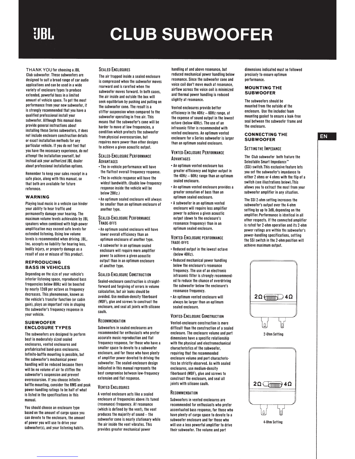
CONNECTING
THE
AMPLIFIER
The
subwoofer
connectors
are
compatible
with
quick-disconnect
(not
supplied)
or
soldered
connections.
The
recommended
wire
gauge
is
between
14AWG
and
BAWG,
depending
on
the
length
of
the
wire
run
between
the
amplifier
and
woofer.
Heavier
gauge
wire
is
preferred
for
runs
over
6'
(2m).
TECHNICAL
DATA
THIELE-SMALL
PARAMETERS
VoiCE-COIL
DC
RESISTANCE:
VOICE-COIL
INDUCTANCE
@
1KHz:
DRIVER
RADIATING
AREA:
MoToR
foRcE
fAcToR:
COMPLIANCE
VOLUME:
SusPENSION
CoMPLIANCE:
MoviNG
MASs,
AIR
LoAD:
fREE-AIR
RESONANCE:
MECHANICAL
Q:
ELECTRICAL
Q:
TOTAL
Q:
MAGNETIC-GAP
HEIGHT:
VOICE-COIL
HEIGHT:
MAXIMUM
EXCURSION:
Club
1024
20
40
REYc
(OHMs)
••••••••
2.00
•••••••••
4.30
LEvc
(MH)
II II
•
IIII
1.21
II II
•
II II
0.77
So
(1N
2)
II II II II II
51.17
IIIIII
II
51.17
So
(cM
2
)~~
IIII
II.
330.10
II
II
II.
330.10
BL(T
.)
II II
II
II II
10.20
II II
IIII
13.60
VAS
(FT
3) I I I I I I I I I I
1.14
I I I I I I I I I
1.08
vAS
(LITERS)
I I I • I I I
32.30
I I I I I I I I
30.60
CMs
(~M/N)
••••••
210.00
••••••••
200.00
MMs
(GRAMS)
••••••
134.00
•••••••
133.90
fs
(Hz)
II II II II II
29,90
II II
11
II
30,70
QMso
I I I I I I I I I I I I I
4.10
I I I I I I I I I
2.60
QEs
I I I I I I I I I I I I I I
0.48.
I I I I I I I I I
0.60
QTs
I I I I I I I I I I I I I I
0.43
I I I I I I I I I I
0.49
HAG
(IN)
I I I I I I I I I I I
0.24.
I I I I I I I I I
0.24
HAG
(MM)
I I I I I I I I I I
6.00.
I I I I I I I I I
6.00
Hvc
(IN)
•••••••••••
0.96
••••••••••
0.96
Hvc
(MM)
II II II II
•
24.50
II
II II II
24.50
XMAX
(IN)
IIII II
II II
0.36
II
II
I
II II
0.36
XMAX
(MM)
II
II II II
9.25
II II II II
I
9.25
SEALED-Box
VoLUME
(INCLUDES
DRIVER
DISPLACEMENT)
0
fZJ1
~~Ill
00000
IIIJij
b:J
(side
view)
V
80
x=
0.50
ft
3
(14.20
liters)
VENTED-BOX
VOLUME
(INCLUDES
DRIVER/PORT
DISPLACEMENTS)
\~
0
\IIIII
00000
IIIIIJ
b:J
(side
view)
V
80
x=
1.5
ft3
(42.51iters)
SPECIFICATIONS
DIAMETER:
SENSITIVITY
(2.83V
@
1M):
PowER
HANDLING:
fREQUENCY
RESPONSE:
NOMINAL
IMPEDANCE:
VOICE-COIL
DIAMETER:
DIMENSIONS:
t
mounting
depth
5-5/8"
(142mm)
•
I·
r
length
=
11.3"
Port
r··
fB
=
30.0Hz
I•
•I
diameter
=
3"
(76mm)
10"
(254MM)
92d8
250W
RMS
(1000W
PEAK)
30Hz
-175Hz
2
OR
4
OHMS
2"
(50MM)
cutout
diameter
I"
(22Bmm)
outer
diameter
10-3/4"
(272mm)
mounting
height
11/16"
(17
mm)
The
wider
terminal
is
the
positive
and
the
narrower
is
negative
(also
indicated
on
the
terminal
cover).
NOTE:
If
using
untlnned
bare
wire,
be
sure
that
no
stray
"+"
and
"-"
strands
touch
each
other.
Touching
strands
can
cause
a
short
circuit,
which
can
damage
your
amplifier.
THIELE-SMALL
PARAMETERS·
VOICE-COIL
DC
RESISTANCE:
VoiCE-COIL
INDUCTANCE
@
1KHz:
DRIVER
RADIATING
AREA:
MOTOR
fORCE
fACTOR:
CoMPLIANCE
VoLUME:
SusPENSION
CoMPLIANcE:
MOVING
MASS,
AIR
LOAD:
fREE-AIR
RESONANCE:
MECHANICAL
Q:
ELECTRICAL
Q:
TOTAL
Q:
MAGNETIC-GAP
HEIGHT:
VOICE-COIL
HEIGHT:
MAXIMUM
ExcuRsioN:
Club
1224
20
40
REvc
(OHMs)
II
IIII
II
2.00
II II II II
•
4.40
LEvc
(MH)
II
IIII
•
/.
1.20
II II
II
II
•
0.81
So
(1N
2)
IIII IIIIII
81.03
II II II II
81.03
So
(cM
2
).
• • • • • • • •
522.80
••••••••
522.80
BL(T.)
II II
II
II II
10.3011
IIII II
I
13.90
VAS
(n
3
)~~
II
II
II II
2.16
II
II
II
II.
2.11
VAs
(LITERS)
•••••••
61.20,
•••••••
59.70
CMs
(~M/N)
••••••
160.00
••••••••
160.00
MMs
(GRAMS)
••••••
155.10
•••••••
154.90
fs
(Hz)
11 11
11
11 11
31.90
11 11 11 11
32,40
QMs
I I I I I I I I I I I I I I
4.64
I I I I I I I I I
3.02
QEs
I I I I I I I I I I I I I I
0.59.
I I I I I I I I I
0.72
QTs
I I I I I I I I I I I I I I
0.52.
I I I I I I I I I
0.58
HAG
(IN)
I I I I I I I I I I I
0.24.
I I I I I I I I I
0.24
HAG
(MM)
I I I I I I I I I I
6.00.
I I I I I I I I I
6.00
Hvc
(IN)
II II II
II
II.
1.12
II II II
II.
1.12
Hvc
(MM)
II II II
II
•
28.50
II II II II
28.50
XMAX
(IN)
II II II II II
0.40
II
II
I
II II
0.40
XMAX
(MM)
I I I I I I I I
10.25
I I I I I I I I
.10.25
SEALED-BOX
VOLUME
(INCLUDES
DRIVER
DISPLACEMENT)
n (ZJj
\UIIU
00000
IIIII_/
b:J
(side
view)
V
80
x=
0.
75
ft
3
(21.20
liters)
VENTED-Box
VoLUME
(INCLUDES
DRIVER/PoRT
DISPLACEMENTS)
\~
~
\lUll
00000
IIII!J
b:J
(side
view)
,
V
80
x=
2.5
ft
3
(70.81iters)
SPECIFICATIONS
DIAMETER:
SENSITIVITY
(2.83V
@
1M):
POWER
HANDLING:
fREQUENCY
RESPONSE:
NOMINAL
IMPEDANCE:
VOICE-COIL
DIAMETER:
DIMENSIONS:
t
mounting
depth
6-1/2"
(165mm)
•
r
length
=
11.
7"
Port
rM
f9=
30.0Hz
I•
•I
diameter=
4"
(102mm)
12"
(305MM)
93d8
275W
RMS
(1100W
PEAK)
25Hz
-175Hz
2
OR
4
OHMS
2"
(50MM)
cutout
diameter
11-1/4"
(285mm)
outer
diameter
12-15/16"
(328mm)
mounting
height
11/16"(17mm)
HARMAN International Industries, Inc. © 2017 HARMAN International Industries, Incorporated.
All
rights reserved.
HARMAN
8500 Balboa Boulevard, Northridge, JBL is a trademark
of
HARMAN International Industries, Incorporated registered
in
the United States and/or other countries.
CA91329USA
www.jbl.com