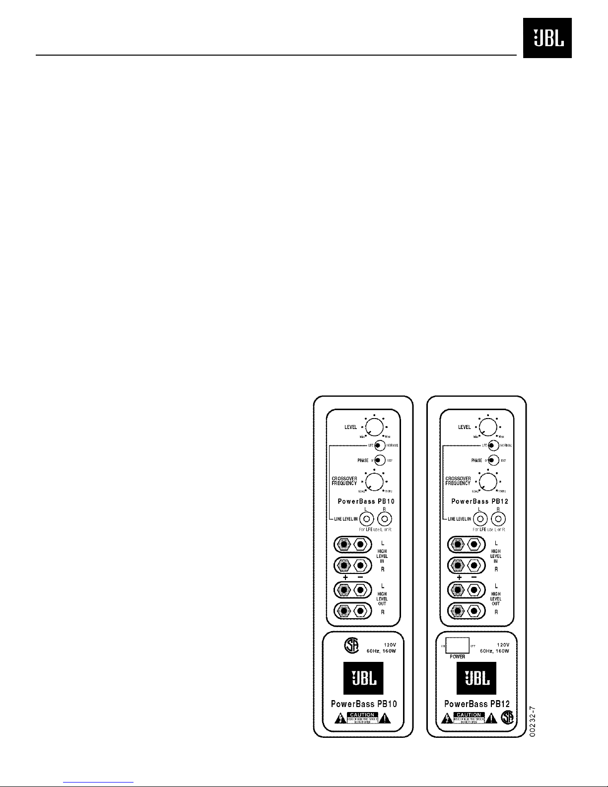
PB10
0
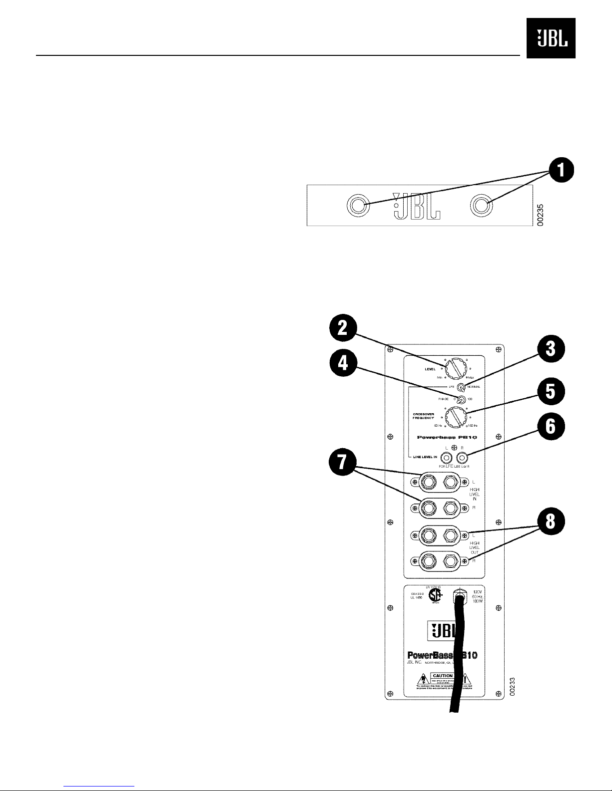
OPERATION
Power
When the unit is plugged in
and the LEDs on the front of
the unit will turn red. When a
signal is present, the LEDs will
turn green.
Note: It will take several
minutes for the LEDs to turn
from green to red after the
input signal to the subwoofer is
removed. Due to JBL’s
unique, high-output, high-
efficiency amplifier design,
power consumption is minimal
when the subwoofer is not
receiving a signal. The PB 0
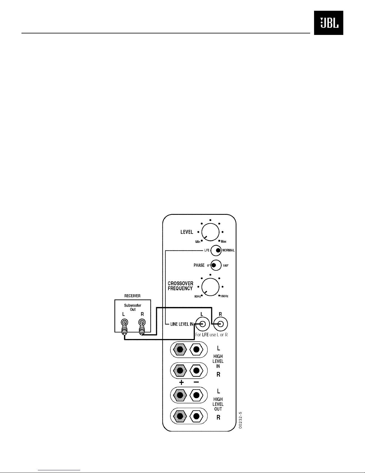
The subwoofer Level Control
adjusts the volume of the
subwoofer relative to the rest
of the system. Proper level
adjustments depends on
several variables such as
Level Control
room size, subwoofer
placement, type of main
speakers and listener position.
Adjust the subwoofer level so
that the volume of the bass
information is pleasing to you.
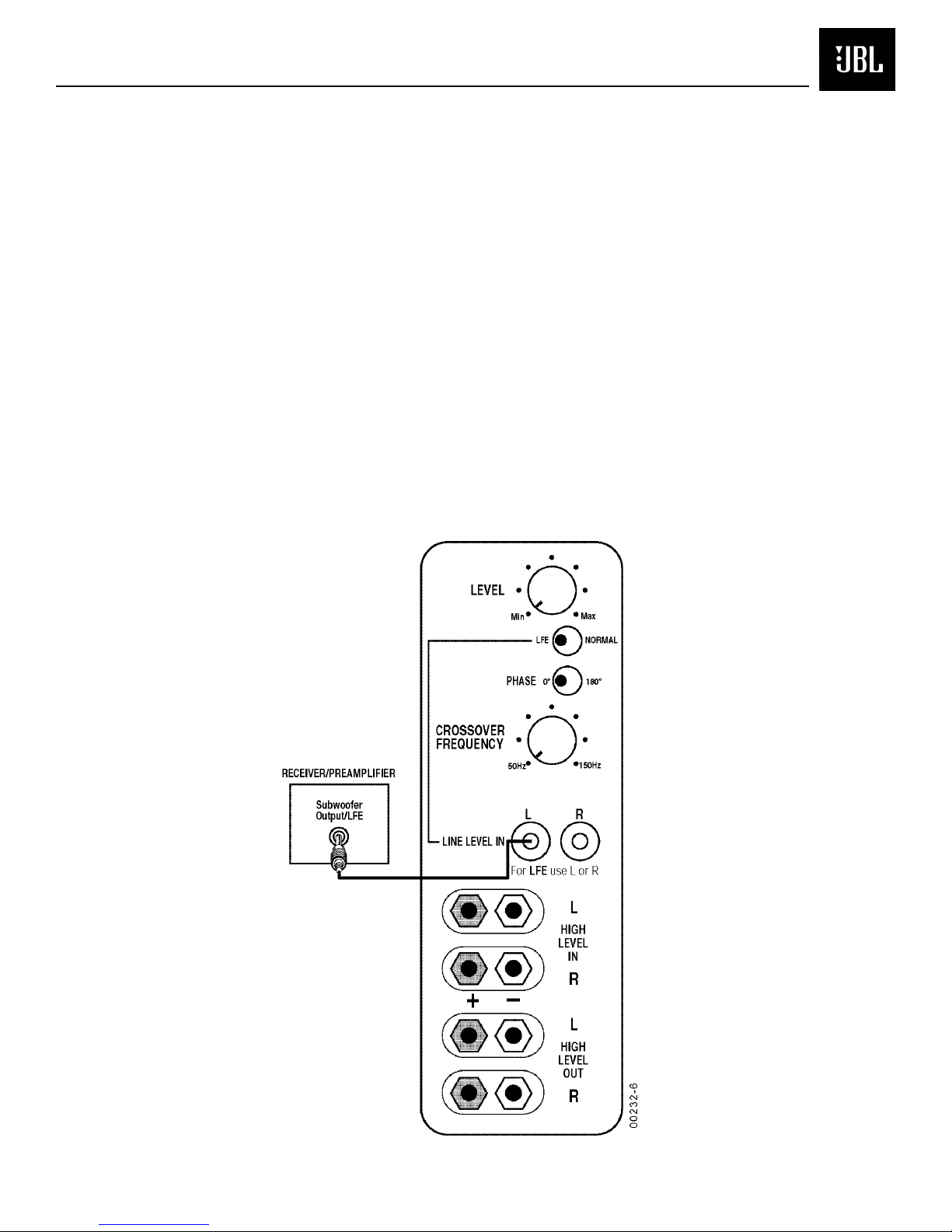
Crossover A justments
The Crossover Frequency
Control determines the highest
frequency at which the
subwoofer reproduces sounds.
If your main speakers can
comfortably reproduce some
low-frequency sounds, set this
control to a lower frequency
setting, between 50Hz- 00Hz.
This will concentrate the
subwoofer’s efforts on the
ultradeep bass sounds required
by today’s films and music. If
you are using smaller bookshelf
speakers that do not extend to
the lower bass frequencies, set
the low-pass crossover control
to a higher setting, between
20Hz- 50Hz. This control is
not used when the LFE switch
is in the “LFE” position.
must be unplugged if you do
not wish to leave it in auto
(standby) mode.