f.
6
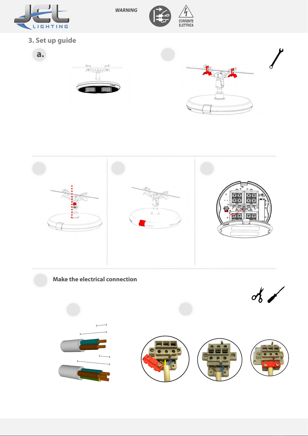
b.
c. d. e.
Before completing the device make sure
you have switched the system’s power o.
1. 2.
6 mm
25 mm
25 mm
6 mm
Make the electrical connection
CLASS II
CLASS I
Tighten the cable
clamp
Strip back the cables as shown in picture 1. Connect the switching station, as a function of the insulation class.Tighten the
block cable red, as shown in Figure 2.
Place the lighting xture on the cable wire. Adjust the
orientation by unscrewing the nut from 3/4 gas positio-
ned under the attack. Maximum rotation of the lantern
/--30 °. Tighten the nut. Secure the safety cord around a
tensioned cable and lock it with spring hook.
Insert the locking clamp in the wire system accessory.
Lock the lighting xture through the tightening of the
M6 screw, coupling torque 5Nm. Tighten the nuts for
device locking.
If you need to back tilt.
Insert the cable into PG16 in the
wire system accessory, and
introduce it inside the luminaire.
Open the lighting xture as shown in
the pictures, by acting on the opening
system.
Slide the cable inside the lantern throu-
gh the fairlead, until it reaches the line
disconnector.
Make the electrical connection
Power cord
bracket
JCL LIGHTING - 70 rue Louis Armand - ZI Les Milles - BP 144 - 13794 Aix-en-Provence Cedex 3 (France) -
Tél : 04-42-24-42-41 - Fax : 04-42-39-73-55 -
[email protected] - www.jcllighting.com


