JCM iVIZION Manual

iVIZION® Banknote Validator Operator’s Guide June, 2014 June, 2014
Part No. 960-100932R_Rev. A © 2014, JCM American, Corporation
16
1
Part No. 960-100932R_Rev. A
For the Americas & Oceania, E-mail: support@jcmglobal.com
For the UK, Ireland, Europe, Africa, Russia & Middle East, E-mail: support@jcmglobal.eu
For Asia E-mail: asiapactechsupport@jcmglobal.com
JCM is a registered trademark of JCM American Corporation. All other product names
mentioned herein may be registered trademarks or trademarks of their respective companies.
Furthermore, ™, ®and ©are not always mentioned in each case throughout this publication.
Operator’s Guide
© 2014, JCM American, Corporation
Operator’s Guide
iVIZION® Banknote Validator
Preventive Maintenance Instructions
This Guide describes procedures for the cleaning and maintenance of the
iVIZION®Banknote Validator. For additional information, refer to Section 2 of
the iVIZION Operation and Maintenance Manual (JCM P/N 960-100929R).
iVIZION REFERENCE DIAGRAMS
Figure 1 identifies the iVIZION™Validator Head, Transport Unit and Cash Box.
• Notes regarding iVIZION Components:
– Sensor locations are shown in yellow.
– Rollers are shown in blue.
– Drive Belts are shown in orange.
– Release levers are shown in green.
– Anti-stringing area is shown in red.
Figure 1 iVIZION Unit, Validator Head, Transport Unit and Cash Box
Typical iVIZION Components
iVIZION Validator Head
Typical iVIZION Unit
(fully assembled)
iVIZION Head and Transport Unit
iVIZION Transport Unit
(inverted) iVIZION Cash Box
PERSONAL NOTES AND COMMENT AREA
Write any pertinent notes or comments regarding your particular installation
here.

Part No. 960-100932R_Rev. A © 2014, JCM American, Corporation Part No. 960-100932R_Rev. A © 2014, JCM American, Corporation
2
15
iVIZION® Banknote Validator Operator’s Guide Operator’s Guide June, 2014
iVIZION PREVENTIVE MAINTENANCE INSTRUCTIONS
Instructions for performing a basic cleaning and maintenance of the JCM
iVIZION Banknote Validator are described below.
TOOLS AND EQUIPMENT
The following Tools and Equipment are required to properly clean your
iVIZION Banknote Validator:
– Two clean, dry lint-free cloths (or micro-fiber cloths)
– Cleaning solution: Warm water with a few added drops of mild, non-abrasive
detergent, such as liquid dishwashing soap)
– Canned compressed air, or a clean, moisture-free source of low pressure
(LP) air
– Medium-bristled Technician’s Cleaning Brush (JCM P/N 501-000097R),
nylon brush or acid brush
– Wood or plastic wand
– PS75-002 (or equivalent 12 Volt DC) Power Supply, or a suitable 24 Volt DC
Power Supply
– JCM Tool Suite Installation Guide - Refer to the Support section at
www.jcmglobal.com
REFERENCE MANUALS
– iVIZION Operations and Maintenance Manual - Refer to the Support section at
www.jcmglobal.com
NOTE: In the following procedures, be sure to use only WARM water with a
small amount of liquid dishwashing soap as a cleaning solution.
Alcohol, thinner, solvents, and citrus-based cleaners SHOULD
NEVER be used. These types of chemicals can cause “hazing” of the
imaging and optical sensors, and premature drying out of the Drive
Belts and Rollers.
NOTE: JCM Global does not recommend the use of any Cleaning Card on
the iVIZION Banknote Validator.
PERSONAL NOTES AND COMMENT AREA
Write any pertinent notes or comments regarding your particular installation
here.

iVIZION® Banknote Validator Operator’s Guide Operator’s Guide June, 2014
Part No. 960-100932R_Rev. A © 2014, JCM American, Corporation Part No. 960-100932R_Rev. A © 2014, JCM American, Corporation
14
3
PREVENTIVE MAINTENANCE SCHEDULE
The iVIZION Banknote Validator will perform at optimal levels when regularly-
scheduled maintenance is performed. The recommended Preventive Mainte-
nance Schedule should be followed based on time periods or acceptance cycles.
The acceptance cycle can be determined by adding the number of Banknotes
accepted to the number of Tickets accepted for a total estimate of acceptance
cycles.
MONTHLY OR 12,000 CYCLES
Every Month or 12,000 Cycles, the following procedures should be performed at
the Machine (approximate time for completion: 30-60 seconds):
INSPECTION
1. Remove the iVIZION Validator from the Machine, and place it on a suitable
work surface.
2. Perform a visual inspection of the entire iVIZION Unit. Look for any broken or
damaged parts that need to be repaired or replaced.
Table 1 Monthly or 12,000 Cycles
Component Procedure Description (Details follow this table)
Validator Head Clean all the Sensor Lenses in the Validator Head (refer to
Figure 2 - iVIZION Validator Head (Yellow Area).
Transport Clean all the Sensor Lenses in the Transport Unit (refer to
Figures 3 and 8 - iVIZION Transport Unit (Yellow Areas).
Transport Clean the Transport Feed-In Sensor Lenses (refer to
Figure 3 - iVIZION Transport Unit - Feed-In Sensor).
Cash Box Clean all the Sensor Lenses in the Cash Box (refer to
Figure 4- iVIZION Cash Box (Yellow Area).
Reinstall and verify proper operation.
NOTE: The actual Maintenance Schedule may vary, due to environmental
conditions and/or usage levels.
CASH BOX PREVENTIVE MAINTENANCE
1. Open the Cash Box and use compressed air or moisture-free low pressure (LP)
air to blow out any dust or debris from inside the Cash Box.
2. Use a damp, lint-free cloth to wipe away any dust, dirt or stains from the Cash
Box Gears.
3. Using a Technician’s Cleaning Brush (JCM P/N 501-000097R), clean any
debris built up on the Cash Box Gears.
4. Using a clean, damp, lint-free cloth, clean the Cash Box Sensors (refer to Figure
10, yellow areas).
5. Use a dry, clean, lint-free cloth to wipe away any dirt, debris and moisture from
the Cash Box.
NOTE: Cash Box Preventive Maintenance should be performed annually
or as needed. Remove the Cash Box from the Game, and then
perform the procedure listed below.
Figure 10 iVIZION Unit and Cash Box
Typical iVIZION Unit
(fully assembled)

Part No. 960-100932R_Rev. A © 2014, JCM American, Corporation Part No. 960-100932R_Rev. A © 2014, JCM American, Corporation
4
13
iVIZION® Banknote Validator Operator’s Guide Operator’s Guide June, 2014
CLEANING THE VALIDATOR HEAD (MONTHLY/12,000 CYCLES)
1. Remove the iVIZION Validator Head (refer to Figures 1 and 2) from the
Transport Unit. To do so:
a). Press the green release (“PUSH”) button on the front of the Validator Head.
b). Pull the Validator Head off and away from the Transport Unit.
2. Open the Validator Head cover by pressing the green-colored release latches on
the left and right sides (refer to Figure 2).
3. Use a clean, lint-free Micro-Fiber cloth (dampened with cleaning solution) to
wipe off any dirt and stains from the surfaces of the Imaging and Optical Sensors.
4. Use a clean, dry Micro-Fiber cloth to perform a second wipe-down of the Bill
Path area, to remove any excess cleaning solution, moisture, residue or haze from
the Imaging and Optical Sensor Lenses. Make sure the entire Bill Path is free of
any smudges, streaks or residue.
NOTE: Be sure to wipe down the entire Bill Path in both the upper and lower
sections of the Validator Head.
Figure 2 iVIZION Validator Head
GENERAL (ANNUAL/144,000 CYCLES)
1. After cleaning, reassemble the iVIZION Validator Head and the Transport Unit,
so that the iVIZION Unit is fully assembled.
2. Calibrate the iVIZION Unit.
3. Using the JCM Tool Suite application, initialize the iVIZION Statistics.
4. If a repair or firmware change is not required, then the iVIZION Cleaning and
Preventive Maintenance procedure is complete. The iVIZION Unit may be
returned to service.
NOTE: Refer to Section 6 of the iVIZION Operation and Maintenance Manual
(JCM P/N 960-100929R) for calibration instructions.
NOTE: Initialization resets the performance numbers to Zero (0) and stores
the date from the PC on the iVIZION Unit for future reference.
NOTE: Repeat the Monthly, 6 Month and Annual Procedures for the next
Preventive Maintenance cycle.
Figure 9 iVIZION Unit (Fully Assembled)

Part No. 960-100932R_Rev. A © 2014, JCM American, Corporation Part No. 960-100932R_Rev. A © 2014, JCM American, Corporation
12
5
iVIZION® Banknote Validator Operator’s Guide Operator’s Guide June, 2014
CLEANING THE TRANSPORT (MONTHLY/12,000 CYCLES)
1. Open the Rear Transport Cover on the Transport Unit. To do so, pull forward on
the green release catch on the top of the Transport Unit, to expose the rear section
of the Transport Unit for cleaning (refer to Figure 3).
2. Use a clean, lint-free Micro-Fiber cloth (dampened with cleaning solution) to
wipe off any dirt and stains from the Optical Sensors (refer to the yellow areas in
Figure 3).
3. Locate the Feed-In Optical Sensor Lenses, directly in front of the Anti-Stringing
Mechanism (refer to the red areas in Figure 3). This area features a grooved
channel in the molding that can collect dust in dirty environments.
4. Use a clean, lint-free Micro-Fiber cloth to wipe the grooved channel clean, and
reduce the risk of false “Bill Jam” errors.
5. Using a clean, lint-free Micro-Fiber cloth (dampened with cleaning solution),
clean and dry the Feed-In Optical Sensor Lenses located on each side of the
Transport Path.
NOTE: Be sure to wipe down the entire Bill Path in both the upper and lower
sections of the Transport Unit.
Figure 3 iVIZION Transport Unit
CLEANING THE TRANSPORT (ANNUAL/144,000 CYCLES)
1. Perform the Monthly Transport Cleaning Procedures (refer to Page 5).
2. Perform the 6 Month Transport Cleaning Procedures (refer to Page 9).
3. Use the JCM Tool Suite application to run the Aging Test. Listen for excessive or
unusual noise.
4. The Transport Unit uses light pipes for the transfer of some optical signals in the
unit. Remove the bottom cover of the Transport Unit to clean the Lenses on the
inside of the Transport Cover where these signals cross over (refer to Figure 8,
yellow areas).
5. Clean the Sensor components on the Processor PCB, using compressed air or
moisture-free low pressure (LP) air to blow out any dust.
6. Remove the Motor Gear Assembly.
7. Remove the Encoder PCB from the Motor Gear Assembly.
8. Use compressed air or moisture-free low pressure (LP) air to blow out any dust or
debris from the gears.
9. Inspect the Motor Drive Gear Assembly for damaged or worn gears.
10. Reinstall the Motor Drive Gear Assembly in the Transport Unit, and then reinstall
the bottom cover.
11. Use a clean, dry, lint-free Microfiber cloth to wipe down the Transport Unit and
remove any cleaning solution, moisture or residue that may remain on the Optical
Sensor Lenses.
NOTE: Perform at least 5 Aging Cycles. If necessary, replace the Motor Gear
Assembly.
NOTE: Refer to Section 4 of the iVIZION Operation and Maintenance Manual
(JCM P/N 960-100929R) for removal instructions.
NOTE: If necessary, replace the Motor Drive Gear Assembly.
Figure 8 iVIZION Transport Unit (Inverted)

iVIZION® Banknote Validator Operator’s Guide Operator’s Guide June, 2014
Part No. 960-100932R_Rev. A © 2014, JCM American, Corporation Part No. 960-100932R_Rev. A ©2014, JCM American, Corporation
6
11
CLEANING THE CASH BOX (MONTHLY/12,000 CYCLES)
The three sets of Cash Box Optical Sensors (refer to the yellow areas in Figure 4)
are not flush-mounted, and often tend to collect dust.
1. Use a clean, lint-free Micro-Fiber cloth (dampened with cleaning solution) to
wipe away any dust, dirt or stains from the Optical Sensor Lenses on the Cash
Box (refer to the yellow areas in Figure 4).
2. Use a dry, clean, lint-free Micro-Fiber cloth to wipe down the Cash Box to
remove any excess cleaning solution, moisture or residue that may remain on the
Optical Sensor Lenses.
3. Reassemble the Validator Head and Transport Unit.
4. Reinstall the iVIZION Unit into the Machine.
5. Verify proper operation.
NOTE: The Cash Box Optical Sensorscan be accessed while the CashBox is
mounted in the Frame.
Figure 4 iVIZION Cash Box
ANNUAL OR 144,000 CYCLES
Every 12 Months or 144,000 Cycles, the following procedures should be
performed in a Service Area (approximate time for completion: 20 Minutes):
INSPECTION
1. Using JCM Tool Suite, check the Statistics for information on performance.
Be sure to note the three most common Error Codes for Banknotes and Tickets.
During the Maintenance Procedure, check areas of the iVIZION Validator that
might generate the noted Error Codes.
2. Perform a visual inspection of the entire iVIZION Unit (Validator Head and
Transport Unit). Look for any broken or damaged parts that need to be repaired
or replaced.
CLEANING THE VALIDATOR HEAD (ANNUAL/144,000 CYCLES)
Perform the Monthly Validator Head Cleaning Procedures (refer to Page 4).
Table 3 12 Months or 144,000 Cycles
Component Procedure Description (Details follow this table)
All Perform the Monthly cleaning procedures (refer to Page 3).
All Perform the 6 Month cleaning procedure (refer to Page 7).
Transport Remove the Transport Unit’s bottom cover, then clean the
inside lens surfaces (refer to Figure 8 - iVIZION Transport
Unit (Yellow Area).
Transport Inspect for gear damage or dirt build-up on the Motor Gear
Assembly and clean as needed.
Complete Unit Run the Aging Test to check for excessive noise, squealing
or errors.
Transport Verify Software Version and update, if necessary.
Complete Unit Calibrate the Unit.
Complete Unit Run the Acceptance Test and verify proper operation.
NOTE: Refer to Appendix A in the iVIZION Operation and Maintenance
Manual (JCM P/N 960-100929R) for Error Codes.

iVIZION® Banknote Validator Operator’s Guide Operator’s Guide June, 2014
Part No. 960-100932R_Rev. A © 2014, JCM American, Corporation Part No. 960-100932R_Rev. A © 2014, JCM American, Corporation
10
7
GENERAL (6 MONTHS/72,000 CYCLES)
1. Reassemble the iVIZION Validator Head and the Transport Unit, so that the
iVIZION Unit is fully assembled.
2. Using the JCM Tool Suite application, initialize the iVIZION Statistics.
3. If a repair, calibration or firmware change is not required, then the iVIZION
Cleaning and Preventive Maintenance procedure is complete. The iVIZION Unit
may be returned to service.
NOTE: Initialization resets the performance numbers to Zero (0) and stores
the date from the PC on the iVIZION Unit for future reference.
Figure 7 iVIZION Unit and Cash Box
Typical iVIZION Unit
(fully assembled)
6 MONTHS OR 72,000 CYCLES
Every 6 Months or 72,000 Cycles, the following procedures should be per-
formed in a Service Area (approximate time for completion: 10-15 Minutes):
INSPECTION
1. Using JCM Tool Suite, check the Statistics for information on performance.
Be sure to note the three most common Error Codes for Banknotes and Tickets.
During the Maintenance Procedure, check areas of the iVIZION Validator that
might generate the noted Error Codes.
2. Perform a visual inspection of the entire iVIZION Unit (Validator Head and
Transport Unit). Look for any broken or damaged parts that need to be repaired
or replaced.
Table 2 6 Months or 72,000 Cycles
Component Procedure Description (Details follow this table)
Inspection Inspect for damaged or broken parts - repair or replace as
required.
Inspection Inspect Belts for wear or damage in the Validator Head and
Transport Unit - Repair or replace as required.
Inspection Inspect Optical Sensor Lenses for damage in the Validator
Head, Transport Unit and Cash Box - Replace Lenses if
scratched, cracked, discolored or damaged.
General Complete the monthly cleaning procedure (refer to Page 3).
Validator Head Clean the Validator Head Rollers (refer to Figure 5 -
iVIZION Validator Head (Blue Area).
Validator Head Clean the Validator Head Belts (refer to Figure 5 - iVIZION
Validator Head (Orange Area).
Transport Clean the Transport Rollers (refer to Figure 6 - iVIZION
Transport Unit (Blue Area).
Transport Clean the Transport Belts (refer to Figure 6 - iVIZION
Transport Unit (Orange Area).
Run the Acceptance Test and verify proper operation.
NOTE: Refer to Appendix A in the iVIZION Operation and Maintenance
Manual (JCM P/N 960-100929R) for Error Codes.

iVIZION® Banknote Validator Operator’s Guide June, 2014
Part No. 960-100932R_Rev. A © 2014, JCM American, Corporation Part No. 960-100932R_Rev. A © 2014, JCM American, Corporation
8
9
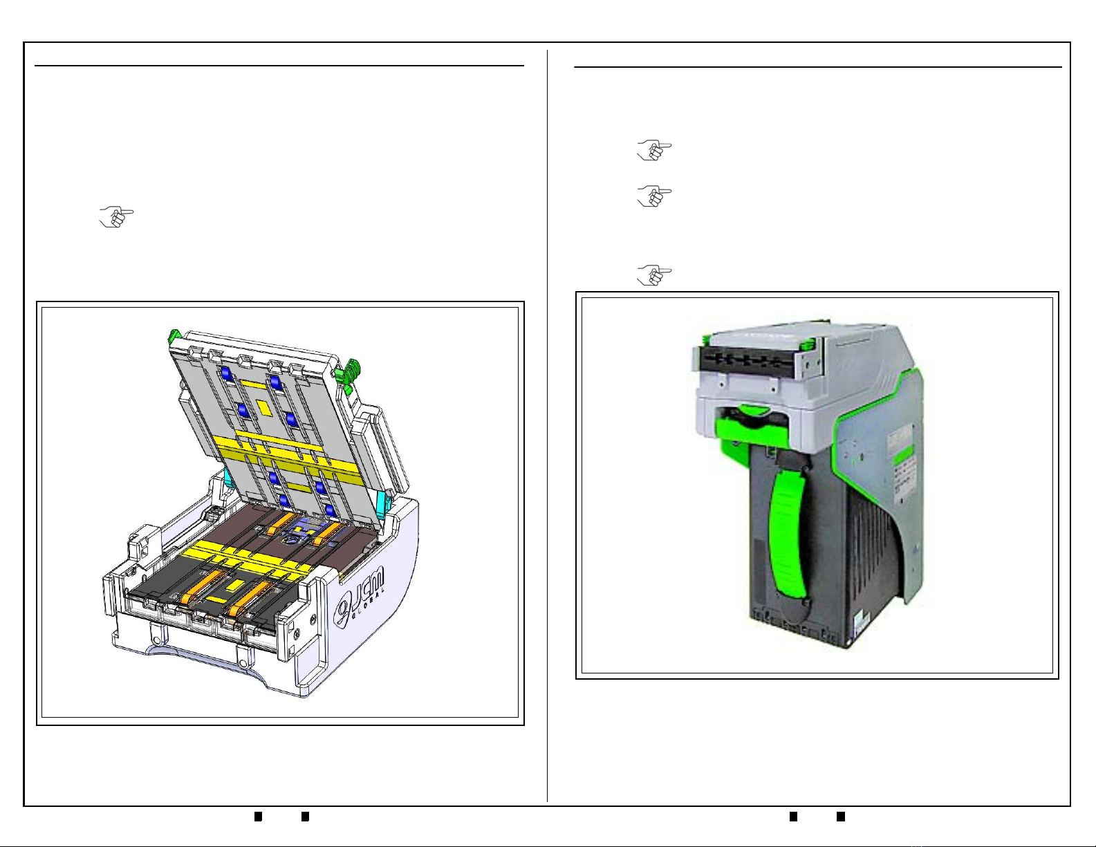
CLEANING THE VALIDATOR HEAD (6 MONTHS/72,000 CYCLES)
1. Perform the Monthly Validator Head Cleaning Procedures (refer to Page 4).
2. Inspect the Drive Belts in the Validator Head (refer to Figure 5, orange areas).
2. Inspect the Imaging and Optical Sensor Lenses on the Validator Head (refer to
Figure 5, yellow areas) for scratches, chips, cracks or discoloration.
3. Using canned, compressed air or a clean, moisture-free source of low pressure
(LP) air, blow out any dust, debris, or paper fibers from the Validator Head.
4. Clean the Rollers in the Validator Head using a Technician’s Cleaning Brush
(JCM P/N 501-000097R) to remove the dirt and any build-up.
5. Clean the Drive Belts in the Validator Head using a clean cloth dampened with
cleaning solution. The Drive Belts in the iVIZION Validator Head can easily be
moved by hand, to allow cleaning of the entire belt.
NOTE: If the Drive Belts are heavily frayed, worn out, or damaged, the belts
should be replaced.
Minor fraying along the left and right edges of the drive belts may
result in “Belt Strings” extending out from the sides of the belts. These
strings can be snipped away with a small pair of scissors. Drive belts
do not need to be replaced if only minor fraying is evident.
NOTE: If a lens has any of these conditions, the lens should be replaced.
NOTE: Use a wood or plastic wand to apply pressure to the side of a Roller, to
keep it from turning during cleaning.
Be careful not to scratch the Rollers! Scratched Rollers will collect dirt
faster, and may require more frequent cleaning.
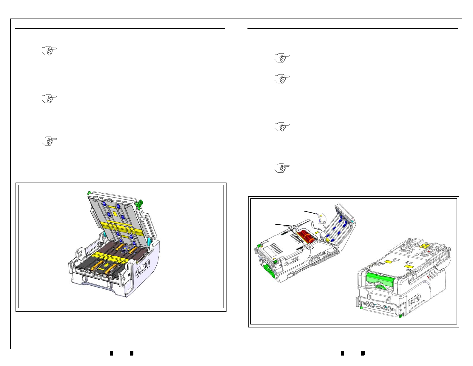
Figure 5 iVIZION Validator Head
CLEANING THE TRANSPORT (6 MONTHS/72,000 CYCLES)
1. Perform the Monthly Transport Cleaning Procedures (refer to Page 5).
2. Inspect the Optical Sensor Lenses on the Transport Unit (refer to Figure 6, yellow
areas) for scratches, chips, cracks or discoloration.
3. Inspect the Drive Belts in the Transport Unit (refer to Figure 6, orange areas).
4. Using canned, compressed air or a clean, moisture-free source of low pressure
(LP) air, blow out any dust, debris, or paper fibers from the Transport Unit.
5. Use a clean, lint-free Micro-Fiber cloth (dampened with cleaning solution) to
wipe off the Rollers in the Transport Unit (refer to Figure 6, blue areas).
6. Use a clean, lint-free Micro-Fiber cloth (dampened with cleaning solution) to
wipe off the Belts in the Transport Unit (refer to Figure 6, orange areas).
.
NOTE: If a lens has any of these conditions, the lens should be replaced.
NOTE: If the Drive Belts are heavily frayed, worn out, or damaged, the belts
should be replaced.
Minor fraying along the left and right edges of the drive belts may
result in “Belt Strings” extending out from the sides of the belts. These
strings can be snipped away with a small pair of scissors. Drive belts
do not need to be replaced if only minor fraying is evident.
NOTE: Be sure to blow out the Anti-Stringing Mechanism and the grooved
channel in front of it (refer to Figure 6).
NOTE: If necessary, use a Technician’s Cleaning Brush (JCM P/N 501-
000097R) to remove residue build-up from the Belts in the Transport
Unit. The Drive Belts can easily be moved by hand, in order to clean
the entire belt.
Figure 6 iVIZION Head and Transport Unit/Inverted Unit
Feed-In
Sensor
Stacker
Sensor Lens
Table of contents
Other JCM Bank Note Validator manuals