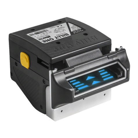
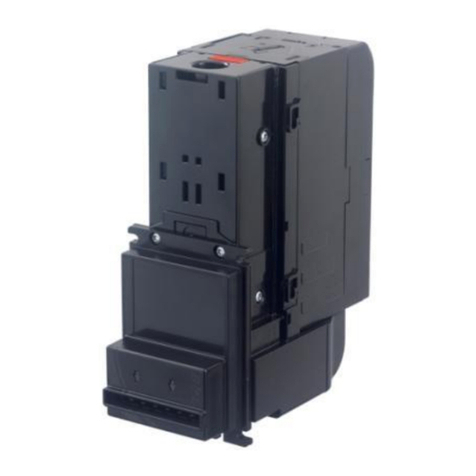
JCM VEGA Series User manual

© 2009, Japan CashMachine Co., Limited
Support: http://www.jcmglobal.com/en/contact/default.aspx Web-Site: http://www.jcmglobal.com
VEGA
™
Series
BankNote Validator
Operation and Maintenance
Manual
(Revision A)
P/N 960-100189RA_Rev. A {EDP #148850}
Issue #4064-SME-01-00

This product document (hereinafter referred to as “Manual”) is fully covered by legal Copyrights owned by the Japan
Cash Machine, Co., Ltd., (hereinafter referred to as “JCM”) under Japanese laws and foreign countries. This Manual
contains many copyrighted, patented or properly registered equipment items manufactured by JCM, that are prohibited
and illegal to duplicate, replicate or copy in whole, or in part, without the express
authorization by JCM with the following exceptions:
1. When an authorized JCM agency or distributor duplicates the Manual for sales promotion and/or service
maintenance of the product, or technical service personnel education as required; and
2. When an end user duplicates the Manual to maintain operation of the product or operate the product in general.
JCM retains all rights to amend, alter, change or delete any portion of this Manual in whole, or in part, or add items
thereto without notice regarding the product or its related products.
JCM is a registered trademark of Japan CashMachine Co, Limited. All other product names mentioned herein may be
registered trademarks or trademarks of their respective companies. Furthermore, ™,
®
and
©
are not always mentioned
in each case throughout this publication.
Copyright © 2009 By Japan CashMachine Co, Limited
VEGA™ Series BankNote Validator Operation and Maintenance Manual
REVISION HISTORY
Rev №.Date Reason for Update Comment
A 8/28/09 Initial Version
1
2
Issue #4064-SME-01-00

P/N 960-100189RA_Rev. A {EDP #148850} © 2009, Japan CashMachine Co., Limited
i
VEGA™ Series
BankNote Validator
Table of Contents
Page
TOC
1 GENERAL INFORMATION.................................................................................. 1-1
Model/Type Number Specifications ........................................................................... 1-2
Precautions .................................................................................................................. 1-2
Installation Precautions .............................................................................................................1-2
User Precautions.......................................................................................................................1-2
Cash Box Handling....................................................................................................................1-3
Mounting & Dismounting the Unit ............................................................................................................1-3
Placing Foreign Objects into the Unit ......................................................................................................1-3
Unacceptable Banknotes.........................................................................................................................1-3
Primary Features ......................................................................................................... 1-4
Component Names...................................................................................................... 1-4
System Configurations ............................................................................................... 1-5
Specifications .............................................................................................................. 1-6
Technical Specifications ...........................................................................................................1-6
Environmental Specifications ...................................................................................................1-6
Electrical Specifications.............................................................................................................1-7
Structural Specifications ............................................................................................................1-7
VEGA Unit Dimensions ............................................................................................... 1-8
Entire Unit Outside Dimensions (Type SH with Standard Cash Box) ........................................1-8
Entire Unit Clearance Dimensions (Type SH with Standard Cash Box)....................................1-8
Entire Unit Outside Dimensions (Type SH with Large Cash Box) .............................................1-9
Entire Unit Clearance Dimensions (Type SH with Large Cash Box) .........................................1-9
Entire Unit Outside Dimensions (Type SD/SU with Standard Cash Box) ................................1-10
Entire Unit Outside Dimensions (Type SD/SU with Large Cash Box) .....................................1-10
Entire Unit Outside Dimensions (Type SD/SU Back Access).................................................. 1-11
VEGA Cash Box Outside Dimensions (Standard Cash Box) .................................................. 1-11
VEGA Cash Box Outside Dimensions (Large Cash Box) .......................................................1-12
VEGA Bezel Outside Dimensions (Type SH) ..........................................................................1-12
VEGA Bezel Outside Dimensions (Type N) ............................................................................1-13
VEGA Bezel Outside Dimensions (Type D) ............................................................................1-13
JCM Contact Information .......................................................................................... 1-14
Americas & Oceania................................................................................................................1-14
JCM American Corporation ...................................................................................................................1-14
Europe, Africa, Russia & Middle East .....................................................................................1-14
JCM Europe GmbH ...............................................................................................................................1-14
UK & Ireland ............................................................................................................................1-14
JCM United Kingdom Ltd.......................................................................................................................1-14
Asia .........................................................................................................................................1-14
JCM Gold (HK) Ltd. ...............................................................................................................................1-14
Japan Cash Machine Co, Limited (HQ) .................................................................................................1-14
2 INSTALLATION/OPERATION ............................................................................. 2-1
Installation....................................................................................................................2-1
Installation Procedure................................................................................................................2-1
DIP Switch Configurations ......................................................................................... 2-2
Basic Settings............................................................................................................................2-2
Special Settings.........................................................................................................................2-3

Table of Contents
P/N 960-100189RA_Rev. A {EDP #148850} © 2009, Japan CashMachine Co., Limited
ii
Page
VEGA™ Series BankNote Validator
Stand-by Mode LED Assignment Indication............................................................................................ 2-3
Rewriting cc-Talk Encryption Code (Initialize)......................................................................................... 2-3
Connector Pin Assignments ...................................................................................... 2-4
Preventive Maintenance ............................................................................................. 2-5
Retrieving Banknotes................................................................................................................ 2-5
Clearing a Banknote Jam .........................................................................................................2
-5
Cleaning Procedure .................................................................................................................. 2-5
Sensor Cleaning Procedure:................................................................................................................... 2-5
Standard Interface Circuit Schematics...................................................................... 2-7
Operational Flowcharts............................................................................................... 2-8
Operational Flowchart (Continued 1) ........................................................................................ 2-9
Operational Flowchart (Continued 2) ...................................................................................... 2-10
3 COMMUNICATIONS ............................................................................................ 3-1
Americas & Oceania ................................................................................................................. 3-1
JCM American Corporation..................................................................................................................... 3-1
Europe, Africa, Russia & Middle East ....................................................................................... 3-1
JCM Europe GmbH................................................................................................................................. 3-1
UK & Ireland ............................................................................................................................. 3-1
JCM United Kingdom Ltd. ....................................................................................................................... 3-1
Asia........................................................................................................................................... 3-1
JCM Gold (HK) Ltd.................................................................................................................................. 3-1
Japan Cash Machine Co, Limited (HQ) .................................................................................................. 3-1
4 DISSASSEMBLY/REASSEMBLY........................................................................ 4-1
Tool Requirements ...................................................................................................... 4-1
CPU Board Removal ................................................................................................... 4-1
Upper Sensor Board Removal ................................................................................... 4-3
Sub-Circuit Board Removal........................................................................................ 4-3
Feed and Stacker Motor Removal.............................................................................. 4-4
Sub-Sensor Board Removal....................................................................................... 4-5
Lower Sensor Board Removal ................................................................................... 4-5
Transport Belt Removal .............................................................................................. 4-5
Stacker Belt Removal.................................................................................................. 4-6
5 WIRING DIAGRAMS ............................................................................................ 5-1
VEGA System Wiring Diagram................................................................................... 5-1
6 CALIBRATION AND TESTING ............................................................................ 6-1
Download Workbench Tool Requirements................................................................................ 6-1
Driver Installation & Software Download Preparation ............................................................... 6-1
Driver Installation Procedure..................................................................................................... 6-2
Software Download Procedure ................................................................................................. 6-3
Calibration Procedures ............................................................................................................. 6-4
When to Calibrate ................................................................................................................................... 6-4
Calibration Types .................................................................................................................................... 6-4
Workbench Calibration Tool Requirements............................................................................... 6-4
Calibration Preparation ............................................................................................................. 6-4
Reference Paper Usage ...........................................................................................................6
-5
Calibration Using a PC ............................................................................................................. 6-6
VEGA_Adjustement.exe Program Use ................................................................................................... 6-6
VEGA_Adjustement_Zero.exe Program Use.......................................................................................... 6-7
Calibration Failure..................................................................................................... 6-10
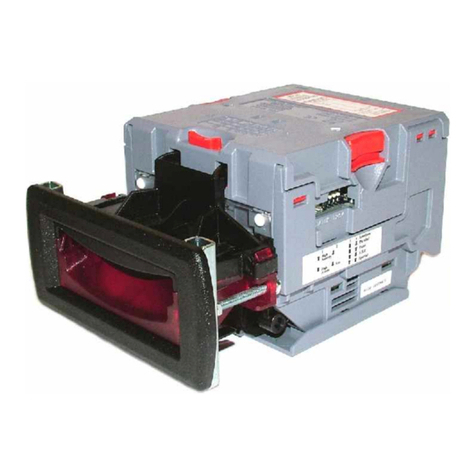
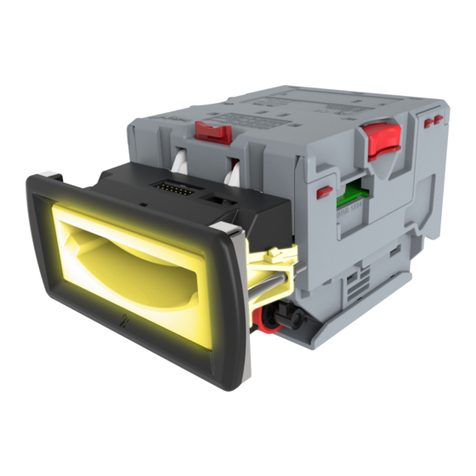
Table of Contents
P/N 960-100189RA_Rev. A {EDP #148850} © 2009, Japan CashMachine Co., Limited
iii
Page
VEGA™ Series BankNote Validator
Activation Failure .................................................................................................................... 6-10
Adjustment Failure.................................................................................................................. 6-10
Adjustment Data Writing Failure ..............................................................................................6-11
Menu Item Functions .................................................................................................6-11
Writing a Serial Number.......................................................................................................... 6-12
Reading a Serial Number ....................................................................................................... 6-12
Reading ccTalk Encryption Code............................................................................................ 6-12
Reading the ccTalk Address ................................................................................................... 6-13
Writing a Stand-by LED Pattern Color .................................................................................... 6-13
Reading a Stand-by LED Pattern Color .................................................................................. 6-13
Reading Adjustment Data ....................................................................................................... 6-13
Reading the VEGA Software Version ..................................................................................... 6-14
Non-PC Calibration Procedure ............................................................................................... 6-14
Performance Tests .................................................................................................................. 6-15
Performance Test Preparation .............................................................................................................. 6-15
Performance Tests Activation ............................................................................................................... 6-16
Performance Test Initiation .....................................................................................................6-16
DIP Switch Test..................................................................................................................................... 6-16
Feed Motor Forward Rotation Test ....................................................................................................... 6-16
Feed Motor Reverse Rotation Test: ...................................................................................................... 6-17
Stacker Motor Test ................................................................................................................................ 6-17
Aging Test ............................................................................................................................................. 6-17
Off-line Banknote Acceptance Test....................................................................................................... 6-18
Sensor Test ........................................................................................................................................... 6-18
7 EXPLODED VIEWS AND PARTS LISTS............................................................. 7-1
Entire VEGA Unit Exploded View (SH) ...................................................................... 7-1
Entire VEGA Unit Exploded View (SD/SU/SDB/SUB) ............................................... 7-2
Entire VEGA Parts List.............................................................................................................. 7-3
Upper VEGA Transport Unit Exploded View ............................................................. 7-4
Upper VEGA Transport Unit Parts List .................................................................................... 7-5
Lower VEGA Transport Unit Exploded View............................................................. 7-6
Lower VEGA Transport Unit Parts List ..................................................................................... 7-7
VEGA Course Path Turning Unit Exploded View...................................................... 7-9
VEGA Course Path Turning Unit Parts List ............................................................................ 7-10
VEGA Cash Box Unit Exploded View .......................................................................7-11
VEGA Cash Box Unit Parts List .............................................................................................. 7-12
VEGA SH Unit Bezel Exploded View........................................................................ 7-14
VEGA SH Unit Bezel Parts List .............................................................................................. 7-15
VEGA SD/SU/SDB/SUB Unit Bezel Type D Exploded View.................................... 7-16
VEGA SD/SU/SDB/SUB Unit Bezel Type D Parts List .......................................................... 7-17
VEGA SD/SU/SDB/SUB Unit Bezel Type N Exploded View.................................... 7-18
VEGA SD/SU/SDB/SUB Unit Bezel Type N Parts List .......................................................... 7-19
VEGA Option Unit Parts Exploded View ................................................................. 7-20
VEGA Option Unit Parts List ................................................................................................... 7-21
8 INDEX ................................................................................................................... 8-1
A TROUBLESHOOTING......................................................................................... A-1
Introduction .................................................................................................................A-1
Troubleshooting Overview .........................................................................................A-1
Fault Table Listings .....................................................................................................A-1

Table of Contents
P/N 960-100189RA_Rev. A {EDP #148850} © 2009, Japan CashMachine Co., Limited
iv
Page
VEGA™ Series BankNote Validator
Malfunction LED Error Code.....................................................................................................A-1
Error and Reject Codes ............................................................................................................A-2
Maintenance Equipment .............................................................................................A-7
VGEA Maintenance Equipment ................................................................................................ A-7
JCM Contact Information............................................................................................A-8
Americas & Oceania .................................................................................................................A-8
JCM American Corporation..................................................................................................................... A-8
Europe, Africa, Russia & Middle East .......................................................................................A-8
JCM Europe GmbH................................................................................................................................. A-8
UK & Ireland ............................................................................................................................. A-8
JCM United Kingdom Ltd. ....................................................................................................................... A-8
Asia...........................................................................................................................................A-8
JCM Gold (HK) Ltd.................................................................................................................................. A-8
Japan Cash Machine Co, Limited (HQ) .................................................................................................. A-8
B GLOSSARY ........................................................................................................ B-1

P/N 960-100189RA_Rev. A {EDP #148850} © 2009, Japan CashMachine Co., Limited
v
VEGA™ Series
BankNote Validator
List of Figures
Page
LOF
Figure 1-1 VEGA Unit Assembly ............................................................................. 1-1
Figure 1-2 Precautionary Symbols .......................................................................... 1-2
Figure 1-3 Unacceptable Banknotes ....................................................................... 1-3
Figure 1-4 VEGA Component Names ..................................................................... 1-4
Figure 1-5 VEGA System Configuration with Host destination example ................. 1-5
Figure 1-6 VEGA Banknote Validator Unit Outside Dimensions
(Type SH - Standard Cash Box) ............................................................ 1-8
Figure 1-7 VEGA Mounting Space Clearance Dimensions
(Type SH - Standard Cash Box) ............................................................ 1-8
Figure 1-8 VEGA Banknote Validator Unit Outside Dimensions
(Type SH - Large Cash Box).................................................................. 1-9
Figure 1-9 VEGA Banknote Validator Unit Outside Dimensions
(Type SH - Large Cash Box).................................................................. 1-9
Figure 1-10 VEGA Banknote Validator Unit Outside Dimensions
(Type SD/SU - Standard Cash Box) ................................................... 1-10
Figure 1-11 VEGA Banknote Validator Unit Outside Dimensions
(Type SD/SU - Large Cash Box).......................................................... 1-10
Figure 1-12 VEGA Banknote Validator Unit Outside Dimensions
(Type SD/SU Rear Access) ................................................................. 1-11
Figure 1-13 VEGA Cash Box Outside Dimensions (Standard Cash Box)............... 1-11
Figure 1-14 VEGA Cash Box Outside Dimensions (Large Cash Box) .................... 1-12
Figure 1-15 VEGA Bezel Outside Dimensions (Type SH) ...................................... 1-12
Figure 1-16 VEGA Bezel Outside Dimensions (Type N)......................................... 1-13
Figure 1-17 VEGA Bezel Outside Dimensions (Type D)......................................... 1-13
Figure 2-1 M4 Nut & DIP Switch Locations ............................................................. 2-1
Figure 2-2 Cable Interconnection ............................................................................ 2-1
Figure 2-3 Bezel Attachment ................................................................................... 2-2
Figure 2-4 M4 Screw & Nut Locations..................................................................... 2-2
Figure 2-5 Cash Box & Guide Cover Location ........................................................ 2-2
Figure 2-6 DIP Switch DS1 (Gradient Color Setting) ................................................ 2-3
Figure 2-7 DIP Switch DS1 (Blue Color Setting) ..................................................... 2-3
Figure 2-8 DIP Switch DS1 (Green Color Setting) .................................................. 2-3
Figure 2-9 DIP Switch DS1 (cc-Talk Initialize)......................................................... 2-3
Figure 2-10 Retrieving Banknotes............................................................................. 2-5
Figure 2-11 Opening the Upper Validation Section................................................... 2-5
Figure 2-12 Retrieving Cash Box Banknote Jam ...................................................... 2-5
Figure 2-13 VEGA Sensor Cleaning Locations ......................................................... 2-6
Figure 2-14 VEGA Photo Coupler Circuit Interface Schematic Diagram .................. 2-7
Figure 2-15 VEGA RS-232C Circuit Interface Schematic Diagram........................... 2-7
Figure 2-16 VEGA ccTalk Circuit Interface Schematic Diagram ............................... 2-7

List of Figures
P/N 960-100189RA_Rev. A {EDP #148850} © 2009, Japan CashMachine Co., Limited
vi
VEGA™ Series BankNote Validator
Page
Figure 2-17 VEGA Banknote Validator Operational Flowchart (Part 1 Full Process).2-8
Figure 2-18 VEGA Banknote Validator Operational Flowchart (Part 2 Stack) ...........2-9
Figure 2-19 VEGA Banknote Validator Operational Flowchart (Part 3 Reject) ........2-10
Figure 4-1 Cash Box & Course Path Reversing Guide Cover Removal...................4-1
Figure 4-2 Cash Box Frame Removal......................................................................4-1
Figure 4-3 Upper Assembly Separation (Part 1) ......................................................4-1
Figure 4-4 Upper Assembly Separation (Part 2) ......................................................4-2
Figure 4-5 Front Bezel Removal...............................................................................4-2
Figure 4-6 Flap Positioning Spring Removals ..........................................................4-2
Figure 4-7 Shaft and Flap #1 & #2 Removal ............................................................4-2
Figure 4-8 Flap Lever Arm Reassembly...................................................................4-2
Figure 4-9 Upper Transport Assembly Removal ......................................................4-3
Figure 4-10 Main CPU Board Removal......................................................................4-3
Figure 4-11 Upper Sensor Board Removal................................................................4-3
Figure 4-12 Base Unit Carrier Removal (Part 1) ........................................................4-3
Figure 4-13 Base Unit Carrier Removal (Part 2) ........................................................4-4
Figure 4-14 Unplug Inter-Assembly Harnesses .........................................................4-4
Figure 4-15 Sub-Circuit Board Removal ....................................................................4-4
Figure 4-16 Gear Box Motor Assembly Removals .....................................................4-4
Figure 4-17 Stacker & Feed Motor Removal..............................................................4-5
Figure 4-18 Sub-Sensor Board Removal ...................................................................4-5
Figure 4-19 Lower Sensor Board Removal................................................................4-5
Figure 4-20 Tension Pulley Unit Removal..................................................................4-5
Figure 4-21 Belt Cover Removal................................................................................4-6
Figure 4-22 Transport Belt Removals ........................................................................4-6
Figure 4-23 Stacker Unit Removal (Part 1) ................................................................4-6
Figure 4-24 Stacker Unit Removal (Part 2) ................................................................4-6
Figure 4-25 Course Path Reversing Guide Removal.................................................4-6
Figure 4-26 E-Ring, Gear & Clutch Shaft Removal....................................................4-7
Figure 4-27 Right Stacker Belt Removal....................................................................4-7
Figure 4-28 Left Stacker Belt Removal ......................................................................4-7
Figure 4-29 Transport Belt Installation .......................................................................4-7
Figure 5-1 VEGA System Wiring Diagram ...............................................................5-1
Figure 6-1 USB Cable Requirement.........................................................................6-1
Figure 6-2 Tool and Harness Connection.................................................................6-1
Figure 6-3 VEGA Port, DIP Switch & LED Indicator Locations ..................................6-2
Figure 6-4 Hardware Wizard Welcome Screen ........................................................6-2
Figure 6-5 Installation Path Selection Screen ..........................................................6-2
Figure 6-6 Install Options Screen.............................................................................6-2
Figure 6-7 Installation Warning Screen ....................................................................6-2
Figure 6-8 Hardware Wizard Completion Screen.....................................................6-3
Figure 6-9 DIP Switch No. 1 Initial Setting ...............................................................6-3
Figure 6-10 UBA Downloader Screen........................................................................6-3
Figure 6-11 VEGA Software Selection Screen ..........................................................6-3

List of Figures
P/N 960-100189RA_Rev. A {EDP #148850} © 2009, Japan CashMachine Co., Limited
vii
Page
VEGA™ Series BankNote Validator
Figure 6-12 Download Progress Screen.................................................................... 6-3
Figure 6-13 Completed Screen.................................................................................. 6-4
Figure 6-14 Reference Paper Types ......................................................................... 6-4
Figure 6-15 PC Calibration Tools & Cabling.............................................................. 6-5
Figure 6-16 Non-PC Calibration Tools & Cabling ...................................................... 6-5
Figure 6-17 Opening VEGA For Paper Placement.................................................... 6-5
Figure 6-18 Type Name Location .............................................................................. 6-5
Figure 6-19 Placing Reference Paper ....................................................................... 6-5
Figure 6-20 Locking Reference Paper In Place......................................................... 6-5
Figure 6-21 DIP Switch Block #1 Initial Settings........................................................ 6-6
Figure 6-22 VEGA Adjustment File Screen ............................................................... 6-6
Figure 6-23 Entrance Sensors Adjustment................................................................ 6-6
Figure 6-24 White Reference Paper Placement Request Screen ............................. 6-6
Figure 6-25 White Reference Paper Calibration Progress Screen ............................ 6-6
Figure 6-26 Black Reference Paper Placement Request Screen.............................. 6-6
Figure 6-27 Black Reference Paper Calibration Progress Screen ............................ 6-7
Figure 6-28 Black Reference Paper Removal Request Screen ................................ 6-7
Figure 6-29 Non-Paper Calibration Screen 1 ............................................................ 6-7
Figure 6-30 Non-Paper Calibration Screen 2 ............................................................ 6-7
Figure 6-31 Motor Speed Test................................................................................... 6-7
Figure 6-32 Adjustment Complete; Request Writing Data To Memory Screen ......... 6-7
Figure 6-33 Writing EEPROM Data Progress Screen ............................................... 6-7
Figure 6-34 The Save As” PC Screen ....................................................................... 6-7
Figure 6-35 VEGA Adjustment Complete Screen...................................................... 6-7
Figure 6-36 DIP Switch Block #1 Initial Settings........................................................ 6-8
Figure 6-37 VEGA Adjustment Zero File Screen....................................................... 6-8
Figure 6-38 Serial No. Input Field Location ............................................................... 6-8
Figure 6-39 Entrance Sensors Adjustment................................................................ 6-8
Figure 6-40 White Reference Paper Placement Request Screen ............................. 6-8
Figure 6-41 White Reference Paper Calibration Progress Screen ............................ 6-8
Figure 6-42 Black Reference Paper Placement Request Screen.............................. 6-8
Figure 6-43 Black Reference Paper Calibration Progress Screen ............................ 6-9
Figure 6-44 Black Reference Paper Removal Request Screen ................................ 6-9
Figure 6-45 Non-Paper Calibration Screen 1 ............................................................ 6-9
Figure 6-46 Non-Paper Calibration Screen 2 ............................................................ 6-9
Figure 6-47 Motor Speed Test................................................................................... 6-9
Figure 6-48 Adjustment Complete; Request Writing Data To Memory Screen ......... 6-9
Figure 6-49 Clearing EEPROM Data Screen ............................................................ 6-9
Figure 6-50 Writing EEPROM Data Progress Screen ............................................... 6-9
Figure 6-51 “Save As” PC Screen ............................................................................. 6-9
Figure 6-52 Calibration Completed Screen ............................................................. 6-10

Figure 6-53 USB Driver Confirmation Screen.......................................................... 6-10

Figure 6-54 Communication Error Screen ............................................................... 6-10
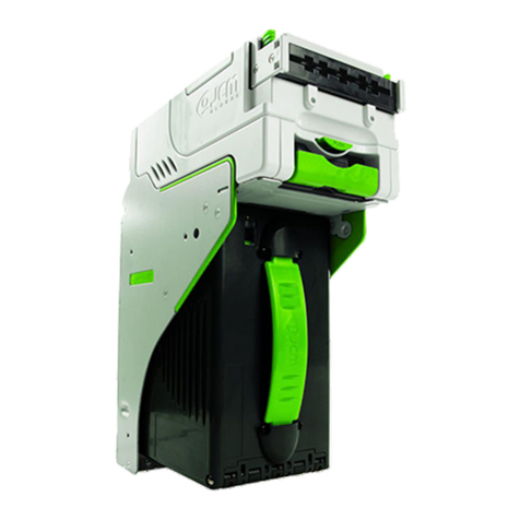
Figure 6-55 Adjust Error Screen .............................................................................. 6-10
List of Figures
P/N 960-100189RA_Rev. A {EDP #148850} © 2009, Japan CashMachine Co., Limited
viii
VEGA™ Series BankNote Validator
Page
Figure 6-56 Retrying Calibration Message Screen ..................................................6-10
Figure 6-57 Calibration Failed Message Screen......................................................6-10
Figure 6-58 Error “Save As” PC Screen...................................................................6-10
Figure 6-59 Duplicate File Name Confirmation ........................................................6-11
Figure 6-60 EEPROM Write Error Screen................................................................6-11
Figure 6-61 Retrying Writing Message Screen ........................................................6-11
Figure 6-62 Data Writing Failure Screen..................................................................6-11
Figure 6-63 Menu Bar Pull-Down Selections 1 ........................................................6-12
Figure 6-64 Serial No. Input Request Screen ..........................................................6-12
Figure 6-65 Serial No. Text Input Field Screen ........................................................6-12
Figure 6-66 Writing Serial No. Complete Screen .....................................................6-12
Figure 6-67 Menu Bar Pull-Down Selections 2 ........................................................6-12
Figure 6-68 Serial No. Read Complete Dialog Screen.............................................6-12
Figure 6-69 Menu Bar Pull-Down Selections 3 ........................................................6-12
Figure 6-70 ccTalk Encryption Code Screen............................................................6-13
Figure 6-71 Menu Bar Pull-Down Selections 4 ........................................................6-13
Figure 6-72 ccTalk Address Read Complete Dialog Screen....................................6-13
Figure 6-73 Menu Bar Pull-Down Selections 5 ........................................................6-13
Figure 6-74 Select LED Pattern Color Screen .........................................................6-13
Figure 6-75 Writing LED Stand-by Indication ...........................................................6-13
Figure 6-76 Menu Bar Pull-Down Selections 6 ........................................................6-13
Figure 6-77 Reading LED Stand-by Indication.........................................................6-13
Figure 6-78 Menu Bar Pull-Down Selections 7 ........................................................6-13
Figure 6-79 Save Adjustment Results Screen .........................................................6-14
Figure 6-80 Menu Bar Pull-Down Selections 8 ........................................................6-14
Figure 6-81 Software Version Read Complete Dialog Screen.................................6-14
Figure 6-82 Non-PC Calibration DIP Switch Block Initial Settings ...........................6-14
Figure 6-83 Tool and Harness Interconnections ......................................................6-15
Figure 7-1 Entire VEGA Unit Exploded View (SH) ...................................................7-1
Figure 7-2 Entire VEGA Unit Exploded View (SD/SU/SDB/SUB) ............................7-2
Figure 7-3 Upper VEGA Transport Unit Exploded View...........................................7-4
Figure 7-4 Lower VEGA Transport Unit Exploded View...........................................7-6
Figure 7-5 VEGA Course Path Turning Unit Exploded View....................................7-9
Figure 7-6 VEGA Cash Box Unit Exploded View ...................................................7-11
Figure 7-7 VEGA SH Unit Bezel Exploded View ....................................................7-14
Figure 7-8 VEGA SD/SU/SDB/SUB Unit Bezel Type D Exploded View.................7-16
Figure 7-9 VEGA SD/SU/SDB/SUB Unit Bezel Type N Exploded View.................7-18
Figure 7-10 VEGA SD/SU/SDB/SUB Unit Bezel Type N Exploded View ................7-20
Figure A-1 Additional Maintenance Equipment Requirements ................................ A-7

P/N 960-100189RA_Rev. A {EDP #148850} © 2009, Japan CashMachine Co., Limited
ix
VEGA™ Series
BankNote Validator
List of Tables
Page
LOT
Table 1-1 Model Number Specifications................................................................... 1-2
Table 1-2 VEGA System Configuration List.............................................................. 1-5
Table 1-3 VEGA Technical Specification.................................................................. 1-6
Table 1-4 VEGA Environmental Specification .......................................................... 1-6
Table 1-5 VEGA Electrical Specification................................................................... 1-7
Table 1-6 VEGA Structural Specification.................................................................. 1-7
Table 2-1 DIP Switch Block 1 Settings ..................................................................... 2-2
Table 2-3 DIP Switch Block 3 Settings ..................................................................... 2-3
Table 2-2 DIP Switch Block 2 Settings ..................................................................... 2-3
Table 2-4 VEGA Pin Assignments............................................................................ 2-4
Table 2-5 VEGA Sensor Cleaning Methods ............................................................. 2-6
Table 6-1 Red Blink Rate Error............................................................................... 6-15
Table 6-2 Performance Test DIP Switch Configuration Settings ............................ 6-16
Table 6-3 Transport Motor Abnormal Error Codes ................................................. 6-17
Table 6-4 Stacker Motor Abnormal Error Codes .................................................... 6-17
Table 6-5 Feeding/Stacking Abnormal Error Codes ............................................... 6-17
Table 6-6 DIP Switch Block DS2 Sensor Configuration Settings ........................... 6-18
Table 7-1 Entire VEGA Parts List ............................................................................. 7-3
Table 7-2 Upper VEGA Transport Unit Parts List ..................................................... 7-5
Table 7-3 Lower VEGA Transport Unit Parts List ..................................................... 7-7
Table 7-4 VEGA Course Path Turning Unit Parts List ............................................ 7-10
Table 7-5 VEGA Cash Box Unit Parts List.............................................................. 7-12
Table 7-6 VEGA SH Unit Bezel Parts List .............................................................. 7-15
Table 7-7 VEGA SD/SU/SDB/SUB Unit Bezel Type D Parts List........................... 7-17
Table 7-8 VEGA SD/SU/SDB/SUB Unit Bezel Type N Parts List........................... 7-19
Table 7-9 VEGA Option Unit Parts List................................................................... 7-21
Table A-1 LED Diagnostics ....................................................................................... A-1
Table A-2 Error Codes .............................................................................................. A-2
Table A-3 Reject Codes ............................................................................................ A-4
Table A-4 Additional Maintenance Equipment Parts Lists ........................................ A-7

P/N 960-100189RA_Rev. A {EDP #148850} © 2009, Japan CashMachine Co., Limited
1-1
VEGA™ Series
BankNote Validator
Section 1
This section provides a general overview of the
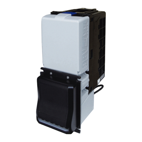
VEGA BankNote Validatior pictured in Figure 1-1.
This first section is designed to help you navigate
through the manual with ease and provides the
following information:
•
Model/Type Number Specifications
•
Precautions
•
Primary Features
•
Component Names
•
System Configuration
•
Specifications
•
VEGA Unit Dimensions.
In order to make operation of this device easier and
make navigation within this manual simpler, the
following illustrations were used within the text:
•
Safety Instructions, which need to be
observed in order to protect both the operators
and equipment, have been written in bold text
and have been given the pictograph:
•
Special Notes,which effect the use of the
Banknote Validator, have been written in italic
text and have been given the pictograph:
•
Steps, requiring the operator to perform
specific actions are given sequential numbers
(1., 2., 3., etc.).
1 GENERAL INFORMATION
Figure 1-1 VEGA Unit Assembly

P/N 960-100189RA_Rev. A {EDP #148850} © 2009, Japan CashMachine Co., Limited
1-2
Section 1 VEGA™ Series BankNote Validator General Information
Model/Type Number Specifications
Precautions
The Figure 1-2 symbols are defined as follows:
1. (Type 1) Do not insert a torn, folded, or wet Ban-
knotes, as this action may cause a Banknote jam
inside the unit.
2. (Type 2) Do not expose the unit to water. The
unit contains several precision electronic devices
which can be damaged into the unit.
3. (Type 3) Do not install the unit into a dusty envi-
ronment. Dust may affect and degrade a Sensor’s
performance.
I
NSTALLATION
P
RECAUTIONS
The following precautions should be observed
when handling and installing a VEGA Unit:
1. This equipment is not fully warranted for outdoor
use. Be sure the Host Machine contains enough
protection to avoid wet or dusty conditions when
installing it in both open-air and indoor spaces.
2. Be sure the Host Machine is designed with
careful consideration for retrieving a Banknote
and/or clearing a Banknote jam.
3. Be careful not to use excessive outside pressure
on the Mounting Plate when removing the Cash
Box from the Unit.
4. Avoid exposing the Banknote Insertion Slot to
direct Sunlight and/or Incandescent Lamp ill-
umination having a Gradient Angle of 15
Degrees or more, and an illumination index of
3000 Lux or less. Insure that the Host Machine is
also designed to avoid exposing the Banknote
Insertion Slot to direct Sunlight or incandescent
light contact.
5. Do not allow the Validator to endure a range of
temperature and humidity beyond the environ-
mental limits specified (See “Environmental
Specifications” on page 1-6 of this Section).
6. Do not use the Validator when placed in severe
Temperature changing environments.
7. Do not use the Validator in a place having air
born evaporated or sporadic chemicals.
8. Clean and maintain the Validator regularly when
located in an excessively smoke filled environ-
ment.
U
SER
P
RECAUTIONS
The following User precautions should be
observed when installing, operating and servicing
the Unit:
1. When closing the Upper portion of the Transport
path or the Course Path Reversing Guide Cover,
ensure that it clicks firmly into place.
Table 1-1: Model Number Specifications
NoModel: VEGA - * * * - *** - **** - * * ** * - ** - **
N
o
(1) (2,3,4) (5) (6) (7,8,9,10)(11) (12)
(1) Product Series Name
(2) CPU Board Type
1. Standard
(3) Durability
0 = Standard
(4) SUB Board
0 = 12V DC Power (NO Magnetic Sensor)
1 = 12V DC Power / Magnetic Sensor
2 = 24V DC Power / NO Magnetic Sensor
3 = 24V DC Power / Magnetic Sensor
(5) Stacker Type
SH = Downward horizontal stacking
SU = Upward vertical stacking
SD = Downward vertical stacking
SUR = Upward vertical stacking (Backside removal)
SDR = Downward vertical stacking (Backside removal)
(6) Country Code
Refer to Specific County’s “Software Information Sheet”
(7) Cash Box
3 = Standard Box
A = Large Box
(8) Lock
0 =Thumb Lock
(9) Bezel
01 = SH 68mm (EUR)
02 = SH 76mm (GBR/SCO/NIRL)
03 = SH 71mm (RUS)
04 = SH 77mm (JPN)
05 = SH 67mm (USA)
N1 = SU/SD 68mm (EUR)
N2 = SU/SD 76mm (GBR/SCO/NIRL)
D1 = SU/SD 67mm (USA)
D2 = SU/SD 71mm (RUS)
D3 = SU/SD 68mm (EUR)
(10) Box Access
F = Front Access
B = Rear Access
(11) Option
00 = NO Option
01 = Frame Key
02 = Bezel Protector
03 = Frame Key + Bezel Protector
(12) Interface
I4 = 4 Types
Type 1Type 2Type 3
Figure 1-2 Precautionary Symbols
Caution: Turn the VEGA’s Power OFF
when opening the Upper or Lower
Guide; otherwise, the Rollers may
begin operating and personal injury to
fingers may occur buy getting them
pulled into the Unit.
Caution: Be careful to avoid personal
injury to your fingers when closing the
Upper Guide Section.

P/N 960-100189RA_Rev. A {EDP #148850} © 2009, Japan CashMachine Co., Limited
1-3
General Information VEGA™ Series BankNote Validator Section 1
2. If the Banknote Validation Section is dirty due to
dust, foreign objects or other such debris adher-
ing to it, Banknote acceptance rate will degrade.
Clean the VEGA Unit once a month to keep its
performance stable.
3. Use a lint-free cloth or cotton swabs to carefully
remove dirt on the Sensors and to remove any
Paper powder dust adhering to the Rollers.
4. Do not redesign or disassemble the VEGA Vali-
dator. Unauthorized use by inadequately trained
personnel, or use outside the original manufac-
turer’s intent for operation voids the warranty.
C
ASH
B
OX
H
ANDLING
Observe the following precautions when handling
a Cash Box:
1. If the Cash Box does not securely mount in place,
have Security Management solve the problem.
2. Do not strike or drop the Cash Box to the ground;
this may cause it to incure remounting damage.
Mounting & Dismounting the Unit
Observe the following precautions when mounting
ans dismounting the Unit:
1. Be sure to turn the Power OFF before mounting
or removing the VEGA Unit from its permanent
location.
2. Plugging or unplugging connector receptacles
while the Power is ON may cause damage to the
Unit.
3. If transporting the VEGA Unit without a Cash
Box, its Frame’s shape may become bent in the
process. Always install a Cash Box into the
VEGA Unit when transporting it.
Placing Foreign Objects into the Unit
Observe the following precautions when placing
foreign objects into the Unit:
1. Do not insert anything except Banknotes into the
Insertion Slot. Inserting Receipts, Stapled Tick-
ets, Rubber Bands, or Credit Cards into the Unit
may damage the Banknote Transport path.
2. Do not inject liquids into the Banknote Insertion
Slot. Injecting water, oil or cleaning agents may
damage the Sensors’ within the Banknote Trans-
port path.
Unacceptable Banknotes
The following Banknote types may not validate
correctly, or can cause a Banknote jam and/or dam-
age to the Unit’s Transport path. Banknotes exhib-
iting the following conditions should be avoided
(See Figure 1-3 ):
•
Torn
•
Having excessive folds
•
Dirty
•
Wet
•
Having excessive wrinkles
•
Adhering foreign objects and/or oil.
WARNING: Under no circumstances
allow a cleaning cloth to be wet enough
to allow excess fluid to run into the
device; internal printed circuit boards
may be damaged. Do not use any
alcohol, citrus based cleaners, solvents
or scouring agents that can damage the
plastic surfaces of the device.
WARNING: Do not inject water or liquid
agents of any kind into the Validator; as
this may cause extreme damage to the
Unit.
Damaged Banknotes
Wrinkled Banknotes
Curled Banknotes
Folded or Partial Banknotes
Figure 1-3 Unacceptable Banknotes

P/N 960-100189RA_Rev. A {EDP #148850} © 2009, Japan CashMachine Co., Limited
1-4
Section 1 VEGA™ Series BankNote Validator General Information
Primary Features
The VEGA contains the following primary
features:
1. The ability to replace an identical VEGA Unit
installation (e.g., a Unit having an SH Specifica-
tion or a SU/SD Specification) into a wide range
of target Host Machines by changing the Face-
plate and the Cash Box Stop location.
2. A single denomination can flow in reverse by
adding the optional VEGA-RC Unit.
Component Names
Figure 1-4 illustrates the VEGA Component Names and Locations.
Figure 1-4 VEGA Component Names
e
a) Upper Section
b) Bezel
c) Upper Section Open/Close Buttons
d) Cash Box
e) USB Connector Receptacle Cover
f) Interface Connector Receptacle
g) Recycler (RC) Connector Receptacle
h) DIP Switches
i) Course Path Reversing Guide
j) Course Path Reversing Guide Cover
Release Buttons
k) Cash Box Door
l) Thumb Lock Knob
m) Banknote Insertion Slot
n) Frame Lock (Option)
a
b
c
d
gf
h
j
l
k
i
m
n

P/N 960-100189RA_Rev. A {EDP #148850} © 2009, Japan CashMachine Co., Limited
1-5
General Information VEGA™ Series BankNote Validator Section 1
System Configurations
Figure 1-5 illustrates a typical VEGA system configuration.
Table 1-2: VEGA System Configuration List
Part Item
aVEGA Unit
bPC (Windows 2000/XP)
cPower Supply (e.g., UAC, MIB232, etc.)
dHost Machine (e.g., Game Machine, Vending Machine etc.)
eInterface Connector (VEGA)
fMaintenance Connector (VEGA)
gStandard Marketplace USB Cable (to VEGA: Mini B Plug/ to PC: Standard A Plug)
hPower Harness
iHarnessa
a. User prepared interface Harness: Refer to “Connector Pin Assignments” on page 2-4 of Section 2 of this Manual for list of the required materials.
a
ef
g
h
i
b
c
d
Figure 1-5 VEGA System Configuration with Host destination example

P/N 960-100189RA_Rev. A {EDP #148850} © 2009, Japan CashMachine Co., Limited
1-6
Section 1 VEGA™ Series BankNote Validator General Information
Specifications
T
ECHNICAL
S
PECIFICATIONS
E
NVIRONMENTAL
S
PECIFICATIONS
Table 1-3: VEGA Technical Specification
Accepted Denomination: Refer to the Specific Country’s “Software Information Sheet”
Acceptance Rate:a
a. Based on new Euro Banknotes. Refer to the “Software Information Sheet” for each Country’s Banknote particular acceptance rate.
95% or greater (including the 1st Banknote returned and 2nd Banknote
accepted)
Note: The following Banknote types are excluded:
a) Banknotes with excess or poor magnetism or unclear graphics.
b) Double (dual) Banknotes.
c) Worn, dirty, wet, stained, torn or excessively wrinkled Banknotes.
d) Banknotes having folded corners or edges.
e) Banknotes having the wrong cut dimensions or printing displacement.
f) Returned Banknote because of incorrect or failed insertion.
g) Banknotes having excessive or insufficient Magnetic-ink (when Magnetic
Sensor contact occurs).
Banknote Types Accepted: Long side: 110~165mm (4.33~6.5 in.).
Short side: 60~82mm (2.36~3.23 in.).
Insertion Direction: Four (4) ways
Validation Method: Optical, 5 wavelength (transparency and reflection)
Processing Speed:b
b. Based on Euro Banknote sizes. Processing time depends on the Host communication time lag.
a) Approximately 2 seconds (from Banknote insertion to vend signal output).
b) Approximately 3 seconds (from Banknote insertion to completion of stacking).
c) Approximately 3 seconds (from Banknote insertion to enable of next
insertion).
Diagnostic Indicators: LED (full-Color range)
Escrow: 1
Banknote
Sequential Operation: Not supported (Sequential Operation by more than 100
Banknotes
is
prohibited).
Anti-stringing Mechanism: Optical and mechanical combination.
Cash Box Capacity: Approximately 300 notes (new
Banknotes
for Standard Cash Box)
Approximately 1000 notes (new
Banknotes
for Large Cash Box).
Cash Box Access: Front or Rear (SH Type).
Upward (SU or SD Type).
Cash Box Type: Standard Cash Box
Large Cash Box.
Interface:c
c. Related Parameters for the respective Interface type or types listed.
Table 1-4: VEGA Environmental Specification
Operating Temperature: 0°C to ~ + 50°C (32°F to ~122°F)a
Storage Temperature: -20°C to ~ + 60°C (- 4°F to ~140°F)a
a. Depends on Hydrothermal conditions
Relative Operating Humidity: 30% to ~80% RH (non-condensed)
Relative Storage Humidity: 10% to ~85% RH (non-condensed)
Visible Light Sensitivity: Avoid contact with direct sunlight (
Interior lighting must be incandescent with a Gradient
Angle of 15 Degree or more, having an Illumination index of 3000 Lux or less
)
Installation: Indoors Only (
Not exposed to the elements, including the internal Unit assemblies
)
a) Photo-coupler Isolation
b) RS232C
c) ccTalk
†
(a~b) = ID-003
†
c) = ID-0E3
35°C/80RH%
50°C/30RH%
Hydrothermal Condition Graph
Allowable
Operating
Temperature and
Humidity Range

P/N 960-100189RA_Rev. A {EDP #148850} © 2009, Japan CashMachine Co., Limited
1-7
General Information VEGA™ Series BankNote Validator Section 1
E
LECTRICAL
S
PECIFICATIONS
S
TRUCTURAL
S
PECIFICATIONS
Table 1-5: VEGA Electrical Specification
Supply Voltagea:
a. Hot-swapping is prohibited (e.g., do not plug connectors in or out while the power is ON).
12V DC (±5%) 2.0A REcommended
12V DC (±5%) 5.0A REcommended (VEGA & VEGA-RC Specification)
Current Consumption: Standby = 0.2A (12V DC)
Operation = 0.7A (Max:0.8A) (12V DC)
Table 1-6: VEGA Structural Specification
Weight: Unit: Approximately 2kg (4.409 lbs)
Cash Box: Approximately 0.8kg (1.763 lbs)
Mounting:a
a. Both vertical and transverse types should be installed at 90 degrees to the Frame.
Horizontal (SH Type)
Vertical Surface Installation (SU/SD Type)
Cash Box Limit Stop:
a) Rear Installation (Front Access) (SHF Type)
b) Front Installation (Rear Access) (SHR Type)
Outer Dimensions: 168mm (6.61 in) High x 221.5mm (8.72 in) Deep x 104mm (4.09 in)
Wide.b
b. Without a 12mm width Faceplate.

P/N 960-100189RA_Rev. A {EDP #148850} © 2009, Japan CashMachine Co., Limited
1-8
Section 1 VEGA™ Series BankNote Validator General Information
VEGA Unit Dimensions
E
NTIRE
U
NIT
O
UTSIDE
D
IMENSIONS
(T
YPE
SH
WITH
S
TANDARD
C
ASH
B
OX
)
Figure 1-6 illustrates the entire VEGA SH Unit with a Standard Cash Box’s outside dimensions.
E
NTIRE
U
NIT
C
LEARANCE
D
IMENSIONS
(T
YPE
SH
WITH
S
TANDARD
C
ASH
B
OX
)
Figure 1-7 illustrates the VEGA SH Unit with Standard Cash Box mounting space clearance dimensions.
NOTE: All Dimension are in Millimeters
Figure 1-6 VEGA Banknote Validator Unit Outside Dimensions (Type SH - Standard Cash Box)
a) Upper Section Open/
Close Button
b) Course Path Reversing
Guide Door Release Button
NOTE: All Dimension are in
Millimeters
Figure 1-7 VEGA Mounting Space Clearance Dimensions (Type SH - Standard Cash Box)
Table of contents
Other JCM Bank Note Validator manuals