JCM DBV Series User manual

1
Part No. 960-000187R_Rev. A
November, 2016
®
© 2016 JCM American Corporation
Phone (800) 683-7248
(702) 651-0000
Fax (702) 651-0214
E-mail [email protected]
www.jcmglobal.com
JCM®TRAINING
OVERVIEW
DBV®Series
DBV-500 Banknote Validator

Part No. 960-000187R_Rev. A © 2016 JCM American Corporation
2
DBV-500 Banknote Validator JCM® Training Overview November, 2016
Page
DBV-500 Banknote Validator
Table of Contents
Overview ................................................................................. 3
DBV-500 SD Unit ..................................................................................... 3
Component Locations ............................................................. 4
Component Names .................................................................................. 4
DIP Switch Settings ................................................................ 5
Communication Settings ......................................................... 6
Setting the LED Bezel Default Color Setting .......................... 7
Sensor and Roller Cleaning Procedure .................................. 8
JCM Tool Suite Standard Edition ............................................ 9
Software Download Procedures ........................................... 10
Performance Testing Procedures ......................................... 12
Performance Testing .............................................................................. 12
Available Tests Using the JCM Tool Suite Application ....................... 12
Available Tests Using DIP Switch Block 1 .......................................... 14
Sensor Test ............................................................................................ 15
Calibration ............................................................................ 16
Validation Sensor Calibration ................................................................. 16
White Level Test ..................................................................................... 18
LED Error Codes .................................................................. 20
Startup Errors ......................................................................................... 20
Operational Errors .................................................................................. 21
Banknote Reject Errors .......................................................................... 22
Personal Notes and Comments ............................................ 23
DBV-500 Parts List ............................................................... 24
Part No. 960-000187R_Rev. A © 2016 JCM American Corporation
3
November, 2016 JCM® Training Overview DBV-500 Banknote Validator
Lecture Notes
OVERVIEW
This training course addresses the following JCM DBV-500 device versions:
DBV-500 SD U
NIT
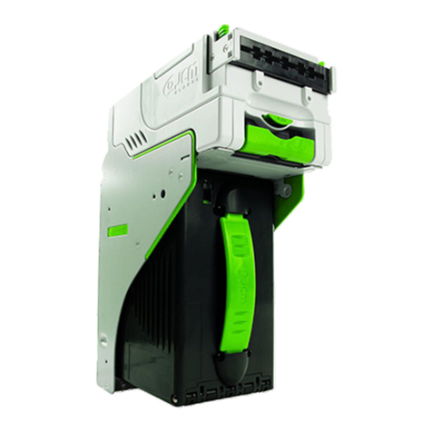
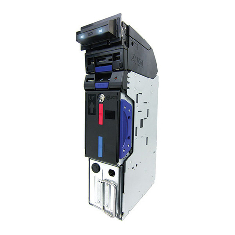
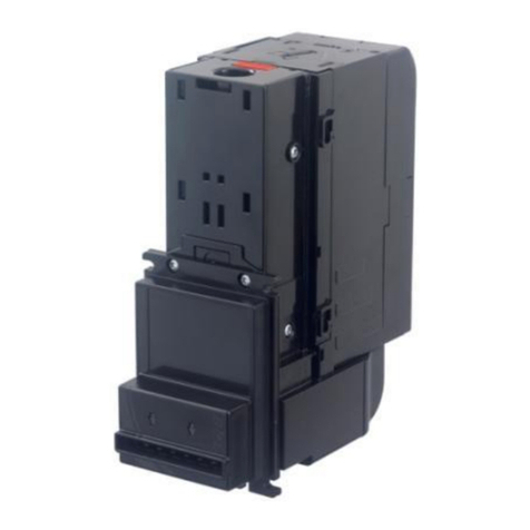
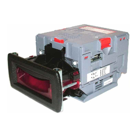
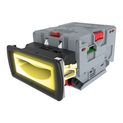
Figure 1 illustrates the DBV-500 SD Banknote Validator Unit.
Table 1 DBV-500 Banknote Validator Versions
Device Version Difference
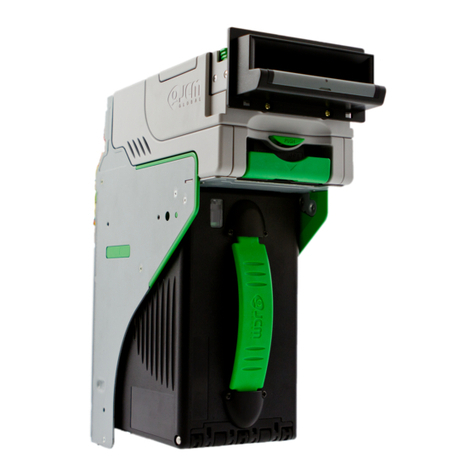
DBV-500 SU Upstack Unit
DBV-500 SD Downstack Unit
Figure 1 Typical DBV-500 SD Unit
SD Unit

Part No. 960-000187R_Rev. A © 2016 JCM American Corporation
4
DBV-500 Banknote Validator JCM® Training Overview November, 2016
COMPONENT LOCATIONS
C
OMPONENT
N
AMES
Figure 2 illustrates the DBV-500 Component Names and Locations.
n
m
l
k
e
Option Items
b
c
a
d
g
f
j
h
i
Figure 2 DBV-500 Component Names
a) Bezel
b) Full-Color Indicator
c) Transport Unit
d) Cash Box
e) Cash Box Latches
f) Unit Guide Open/Close Latches
g) USB Connector (for Maintenance)
h) Power/Interface Connector
i) DIP Switch Block #1
j) DIP Switch Block #2
k) Cash Box Handle
l) Frame Lock
m) Plastic Latch
n) Metal Lock

Part No. 960-000187R_Rev. A © 2016 JCM American Corporation
5
DBV-500 Banknote Validator JCM® Training Overview November, 2016
Lecture Notes
DIP SWITCH SETTINGS
Table 2 lists the default Configuration Settings for the DBV-500 DIP Switch
Block #1. Table 2 DIP Switch Block #1 Configuration Settings*
* See the Software Information Sheet (SIS) for proper Switch Settings.
Switch No. Switch ON Switch OFF
1 VEND 1 INHIBIT VEND 1 ACCEPT
2 VEND 2 INHIBIT VEND 2 ACCEPT
3 VEND 3 INHIBIT VEND 3 ACCEPT
4 VEND 4 INHIBIT VEND 4 ACCEPT
5 VEND 5 INHIBIT VEND 5 ACCEPT
6 VEND 6 INHIBIT VEND 6 ACCEPT
7OFF OFF
8 TEST MODE OFF (OPERATING MODE)
ON
OFF

Part No. 960-000187R_Rev. A © 2016 JCM American Corporation
6
November, 2016 JCM® Training Overview DBV-500 Banknote Validator
Lecture Notes
COMMUNICATION SETTINGS
The DBV-500 Banknote Validator supports the following communication
interface types:
Table 3 lists the default Configuration Settings for DIP Switch Block #2.
– Photo-Coupler (9600 bps) – Pulse
– TTL (38400 bps) – USB 2.0*
* USB Communications requires an external harness for USB connection.
– RS-232C (38400 bps)
Table 3 DIP Switch Block #2 Configuration Settings (Default)
Switch
No.
DIP Switch #2*
* For correct DIP Switch Block #2 Settings for other protocols, check the Software Information
Sheet (SIS) for the specific protocol.
ID-003 ID-0E4
Photo
Coupler TTL RS-
232C TTL RS-
232C
Baud
Rate
9600
bps
Baud
Rate
19200
bps
Baud
Rate
38400
bps
Baud
Rate
115200
bps
1 OFF ON OFF OFF ON
2OFFOFFON OFF ON OFF ON
3
OFF = Standard ID-003
OFF OFF ON ON
ON = Send Enable or
Disable Status before
Stacker Full
4 OFF OFF OFF
5 OFF OFF OFF
6 OFF OFF OFF
7OFF = Standard Current Mode [Peak Current: 3.0A]
ON = Maximum Current Limitation Mode [Peak Current: 2.0A]
8OFF = ID-003 Mode
ON = ID-0E4 Mode

Part No. 960-000187R_Rev. A © 2016 JCM American Corporation
7
Lecture Notes
DBV-500 Banknote Validator JCM® Training Overview November, 2016
SETTING THE LED BEZEL DEFAULT
COLOR SETTING
To set or change the LED Bezel default color setting, proceed as follows:
1. Remove power from the DBV-500 Banknote Validator Unit.
2. Set the DBV-500 DIP Switch Block #1 (Switches #1, #4, #5, #6, #7 and #8)
settings to ON.
3. Restore power to the DBV-500 Banknote Validator Unit.
4. Select the desired Bezel LED Color SOLID ON by setting DIP Switch Block #2 as
indicated in Table 4 below.
5. Set DIP Switch Block #1 Switch #8 to OFF to save the Bezel LED color
configuration.
6. Remove power from the DBV-500 Banknote Validator Unit.
7. Reset all DIP Switch settings on DIP Switch Block #1 and Block #2 to the
original settings.
NOTE: Before changing settings, record the current settings of DIP Switches #1
through #8 in DIP Switch Block #2. These settings will need to be restored in order to
complete this procedure.
NOTE: To change the Bezel LED Color from a SOLID ON to a Flashing (ON/OFF)
display, set the DIP Switch Block #2 Switches (Table 4) ON for the desired LED Color,
then set Switch #8 ON to enable the Flashing function for the selected LED Color.
Table 4 LED Bezel Color Settings [Enable (Idling) State]
Bezel
LED Color DIP Switch Block #2 Settings
12345678
GREEN ON
CYAN ON
BLUE ON
MAGENTA ON
WHITE ON
YELLOW ON
RED ON
GRADIENT
(FADING) ON ON ON ON ON ON ON
LED OFF ON ON ON ON ON ON ON ON

Part No. 960-000187R_Rev. A © 2016 JCM American Corporation
8
DBV-500 Banknote Validator JCM® Training Overview November, 2016
SENSOR AND ROLLER CLEANING PROCEDURE
To clean the DBV-500 Unit, gently wipe the Sensors and Rollers using a clean
(slightly damp) lint-free Microfiber cloth.
1. Turn the DBV-500 Unit Power OFF.
2. Open the Validation Guide.
3. Clean the Lens of each Sensor (yellow) and the Rollers (green). (See Figure 3
for Locations and Table 5 for Cleaning Methods.)
4. Calibrate the DBV-500 Unit after cleaning.
Table 5 DBV-500 Sensor and Roller Cleaning Methods
Label Sensor Description Cleaning Method
aEntrance Sensor
bCentering Start Sensor
cSide Sensor
dCOB Sensor
eExit Sensor
NOTE: DO NOT use Alcohol, solvents, citrus-based products or scouring agents.
These items may cause damage to the Validation Section Sensors and Rollers.
e
g
a
a
b
e
d
a
b
e
c
b
a
NOTE: Clean the surface of each Roller
(green) using a clean (slightly damp)
lint-free Microfiber cloth.
NOTE: Always calibrate the
DBV-500 Unit after cleaning!
Figure 3 DBV-500 Sensor and Roller Locations
Wipe Sensors (yellow areas) clean using a
clean (slightly damp) lint-free Micro-fiber cloth.
Wipe Rollers (green areas) clean using a
clean (slightly damp) lint-free Microfiber cloth.

Part No. 960-000187R_Rev. A © 2016 JCM American Corporation
9
November, 2016 JCM® Training Overview DBV-500 Banknote Validator
JCM TOOL SUITE STANDARD EDITION
Figure 4 illustrates the JCM Tool Suite Standard Edition’s Main Screen.
The JCM Tool Suite Standard Edition supports the following operational
modes and User-selectable Functions, under the “Service Mode” drop-down
Menu:
The available Service Mode Functions include:
• Normal Mode or Operational Mode
(All DIP Switch Block #1 Switches = OFF):
– Download
– Statistics
– Event Log View
• Test Mode (DIP Switch Block #1 Switch #8 = ON):
– Download
– Statistics
– Sensor Adjustment
– Performance Test
– Event Log View
Use a Standard USB Type-A to Mini-B Cable between the PC and DBV-500.
1. Remove the Cash Box.
2. Connect the Mini-B cable to the USB Port by the DIP Switches.
3. Connect the Type-A connector to the USB Port on the PC.
4. Apply power to the DBV-500 Unit.
5. Open the JCM Tool Suite Application. When connected, the Device Information
Fields will be filled in, as shown in Figure 4.
NOTE:
For DBV-500, JCM Tool Suite Version 1.29 or higher is required.
Figure 4 JCM Tool Suite Main Screen
NOTE:
All Diagnostics Tests can also be performed by setting various DIP Switch
settings. For more information on setting the DIP Switches for testing, refer to Section 6
in the DBV
®
Series DBV-500 Operation and Maintenance Manual (
P/N 960-100933R
{EDP #233449}
).

Part No. 960-000187R_Rev. A © 2016 JCM American Corporation
10
DBV-500 Banknote Validator JCM® Training Overview November, 2016
Lecture Notes
SOFTWARE DOWNLOAD PROCEDURE
To update the Software Version in the DBV-500 Unit:
1. Click the “Service Mode” drop-down menu (Figure 5 a), then click “Download.”
The JCM Downloader Suite Edition display appears (Figure 6).
2. To select the file to download, click “Browse” (Figure 6 a).
3. From the folder that contains the DBV-500 download file, click the DBV-500
Download file name, then click the “Open” screen button.
The JCM Downloader Suite Edition Version x.xx display reappears.
4. Click “Download” to start the file transfer (Figure 6 b).
Figure 5 JCM Service Mode Drop-Down Menu
a
NOTE: A Blue Barograph will display the download progression.
When downloading is complete, the DBV-500 Unit will automatically reset, and
the Online message will be displayed (Figure 6 c).

Part No. 960-000187R_Rev. A © 2016 JCM American Corporation
11
DBV-500 Banknote Validator JCM® Training Overview November, 2016
Lecture Notes
5. Verify that the Host CRC and Device CRC values are identical (Figure 6 d).
6. Disconnect the USB Cable used for the Download, and remove power from the
DBV-500 Unit.
7. Set the DIP Switches on the DBV-500 Unit to the Operational position.
.
Figure 6 Downloader Suite Display
=dc
a
b
NOTE: If the DBV-500 Software becomes corrupted or is not installed (e.g., when
changing the CPU Circuit Board), set Forced Download Mode by setting DIP Switch
Block #1 Switches #6, #7 and #8 ON. (The DIP Switches are located behind the Cash
Box; remove the Cash Box to gain access).

Part No. 960-000187R_Rev. A © 2016 JCM American Corporation
12
Lecture Notes
DBV-500 Banknote Validator JCM® Training Overview November, 2016
PERFORMANCE TESTING PROCEDURES
P
ERFORMANCE
T
ESTING
Available Tests Using the JCM Tool Suite Application
• Transport Motor Normal Rotation
• Transport Motor Reverse Rotation
• Stacking
•SensorTest
• DIP Switch 1 Test
• DIP Switch 2 Test
•LEDTest
•CenteringTest
To run Performance Tests, proceed as follows:
1. Disconnect the DBV-500 Unit from its power source.
2. Remove the DBV-500 Unit’s Cash Box to access the Maintenance USB Port.
3. Set DIP Switch Block #1, Switch #8 ON.
4. Reconnect the DBV-500 Unit to its power source.
5. Connect a USB Type-A to Mini-B cable between the PC’s USB Port and the
DBV-500 Maintenance USB Port.
6. Launch the “JCM Tool Suite Standard Edition” software application.
7. Click the Service Mode drop-down menu (Figure 5), then select Performance Test
(refer to Figure 7 on the following page).
8. Click on the desired Performance Test in the left column (e.g., STACK TEST).
9. Click the “Start” Screen Button to begin the Performance Test.
Test Results are displayed in the Performance Test window (right column).
10.Click the “Stop” Screen Button to end the selected Performance Test.
NOTE: Additional tests are available using DIP Switch Performance Testing
Procedures.
NOTE: Repeat Steps 8 through 10 above to run additional Performance Tests.

Part No. 960-000187R_Rev. A © 2016 JCM American Corporation
14
November, 2016 JCM® Training Overview DBV-500 Banknote Validator
P
ERFORMANCE
T
ESTING
Available Tests Using DIP Switch Block #1
Table 6 below lists the available Performance Tests using DIP Switch Block #1,
and the settings required for each test.
To run Performance Tests using DIP Switch Settings, proceed as follows:
1. Disconnect the DBV-500 Unit from its power source.
2. Remove the DBV-500 Unit’s Cash Box.
3. Set DIP Switch Block #1, Switch #8 ON.
4. Reconnect the the DBV-500 Unit to its power source.
5. Set the appropriate DIP Switch(es) to ON as shown in Table 6.
6. Set DIP Switch Block #1, Switch #8 OFF to begin the Performance Test.
7. Confirm correct operation.
8. Set DIP Switch Block #1, Switch #8 ON to end the selected Performance Test.
NOTE: To perform the Acceptance Test:
1. Turn DIP Switch Block #1 Switch 8 OFF.
2. Set the Cash Box onto the DBV-500 Unit.
The Acceptance Test will begin automatically.
Table 6 Performance Tests Using DIP Switch Settings
Test Item DIP Switch Block #1 Settings Test
Description
12345678*
* DIP Switch Block #1 Switch 8 Setting: OFF to start Test, ON to stop Test.
Transport Motor
Normal Rotation ON ON/
OFF Normal Rotation
Speed Test
Transport Motor
Reverse Rotation ON ON/
OFF Reverse Rotation
Speed Test
Stacking Test ON ON/
OFF
Stacking Mechanism
Movement (check @
3 second intervals)
Aging Test ON ON/
OFF
Aging Movement
(check @ intervals set
by DIP SW1 #6 & #7)
Centering
Mechanism ON ON ON/
OFF
Centering Mechanism
Movement (check @
3 second intervals)
Sensor Test ON ON/
OFF Each Sensor
Performance Check†
† Refer to Sensor Test and Table 7 on page 15 for Sensor and LED Conditions for the Sensor
being tested.
Acceptance Test
(with Validation) ON ON ON ON ON/
OFF Acceptance Check
with Validation
Acceptance Test
(No Validation) ON ON ON ON ON ON/
OFF Acceptance Check
without Validation
Reject Test
(No Validation) ON ON ON ON ON ON ON/
OFF Reject Check without
Validation
DIP Switch #1 Test ON ON ON ON ON ON ON ON/
OFF DIP Switch #1
Performance Check
DIP Switch #2 Test ON ON ON ON ON ON ON/
OFF DIP Switch #2
Performance Check
LED Test ON ON ON ON ON/
OFF LED
Performance Check

Part No. 960-000187R_Rev. A © 2016 JCM American Corporation
15
DBV-500 Banknote Validator JCM® Training Overview November, 2016
Lecture Notes
S
ENSOR
T
EST
To test each sensor, block each Sensor, then consult Table 7 and confirm the
Bezel LED color changes to the correct color for the Sensor being tested.
Table 7 Sensor and LED Condition*
* If multiple sensors are active, the status of the sensor with lowest priority is
shown.
Sensor Name Condition LED
Entrance Sensor Shielded RED
Centering Sensor Shielded GREEN
Validation Sensor Shielded BLUE
Exit Sensor Shielded YELLOW
Stacker Home
Position Sensor
When the Pusher Plate is
NOT at Home Position MAGENTA
Centering Home
Position Sensor
When the Centering
Mechanism is NOT
at Home Position
CYAN
Box Detection
Sensor
When the Cash
Box is installed WHITE

Part No. 960-000187R_Rev. A © 2016 JCM American Corporation
16
DBV-500 Banknote Validator JCM® Training Overview November, 2016
CALIBRATION
Calibration of the DBV-500 Unit needs to be performed when any of the
following conditions occur:
• When removing and replacing the CPU Circuit Board
• When removing or replacing any Sensors or Sensor Boards
• After cleaning the DBV-500 Unit
• If the Banknote Acceptance rate has decreased.
V
ALIDATION
S
ENSOR
C
ALIBRATION
To perform the DBV-500 Validation Sensor Calibration procedure:
1. Disconnect power from the DBV-500 Unit.
2. Set DIP Switch Block #1, Switch # 8 to ON.
3. Restore power to the DBV-500 Unit.
4. Connect the USB Type-A to Mini-B cable between your PC’s USB port and the
USB port located on the DBV-500 Unit.
5. Launch the “JCM Tool Suite Standard Edition” software application.
6. Click the Service Mode drop-down menu (Figure 5), then click Sensor Adjust-
ment.
7. Confirm that the DBV-500 Calibration Tool is running, as shown in Figure 8.
8. Click the Sensor Calibration function screen button (Figure 8 a).
The Sensor Calibration screen appears momentarily (refer to Figure 9).
NOTE: KS-091 Reference Paper is specified for use when calibrating the DBV-500.
NOTE: The DBV-500 Unit’s Front Bezel LED will flash Green.
a
Figure 8 DBV-500 Calibration Tool

Part No. 960-000187R_Rev. A © 2016 JCM American Corporation
17
DBV-500 Banknote Validator JCM® Training Overview November, 2016
9. Follow the onscreen prompts and click the Start button (Figure 9 a) to begin the
DBV-500 Validation Sensor Calibration.
10.When prompted to Change Serial Number?, click Yes if the Serial Number
recorded on the CPU Circuit Board needs to be changed; otherwise, click No to
complete Calibration.
11.When the Sensor Calibration Screen appears (Figure 10), click the Start button
(Figure 10 a) to save the Calibration Settings to EEPROM.
NOTE: KS-091 Reference Paper must be used for Calibration of the DBV-500.
a
Figure 9 DBV-500 Sensor Calibration Function
a
b
Figure 10 DBV-500 Sensor Calibration Results

Part No. 960-000187R_Rev. A © 2016 JCM American Corporation
18
November, 2016 JCM® Training Overview DBV-500 Banknote Validator
Lecture Notes
12.When the “Write EEPROM Succeeded” prompt appears, click the “OK” screen
button to close the screen. Then click the Close box (Figure 10 b) to close the
Sensor Calibration Screen and complete the Calibration process.
W
HITE
L
EVEL
T
EST
To perform the DBV-500 White Level Test procedure:
1. Disconnect power from the DBV-500 Unit.
2. Set DIP Switch Block #1, Switch # 8 to ON.
3. Restore power to the DBV-500 Unit.
4. Connect the USB Type-A to Mini-B cable between your PC’s USB port and the
USB port located on the DBV-500 Unit.
5. Launch the “JCM Tool Suite Standard Edition” software application.
6. Click the Service Mode drop-down menu, then click Sensor Adjustment.
7. Confirm that the DBV-500 Calibration Tool is running, as shown in Figure 11.
8. Click the White Level Test function screen button (Figure 11 a).
The White Level Test screen appears momentarily (refer to Figure 12).
NOTE: The DBV-500 Unit’s Front Bezel LED will flash Green.
a
Figure 11 DBV-500 Calibration Tool

Part No. 960-000187R_Rev. A © 2016 JCM American Corporation
19
DBV-500 Banknote Validator JCM® Training Overview November, 2016
9. Follow the onscreen prompts and click the Start button (Figure 12 a) to begin
the DBV-500 White Level Test.
10.When the White Level Test is complete, click the Close box (Figure 13 a)
to close the White Level Test Screen and complete the process.
NOTE: KS-091 Reference Paper must be used for Calibration of the DBV-500.
a
Figure 12 DBV-500 White Level Test Function
a
Figure 13 DBV-500 White Level Test Complete

Part No. 960-000187R_Rev. A © 2016 JCM American Corporation
20
November, 2016 JCM® Training Overview DBV-500 Banknote Validator
Lecture Notes
LED ERROR CODES
S
TARTUP
E
RRORS
Startup Errors can occur during initial power up of the DBV-500 Unit. During
Normal Operating Mode, the Bezel LED flashes white; in Performance Test
Mode, however, the Bezel LED flashes white intervals. To identify the Startup
Error, count the flashes between pauses, then consult Table 8 to determine the
Error, Causes and Solutions.
Table 8 DBV-500 Startup Errors, Causes and Solutions
Normal
Operation Performance
Test Error Causes and Solutions
White (1) White (1) Boot Check Boot Program incorrectly written - CPU Board
White (3) White (2) Boot I/F Boot interface incorrectly written/No Operating
Program - Download the software, CPU Board
White (3) White (3) CPU Internal
RAM RAM Reading/Writing Error, CPU Board
White (3) White (4) External
SD RAM
SD-RAM Reading/Writing Error, Download
Software, CPU Board
White (3) White (5) EEPROM EEPROM Reading/Writing Error, Calibrate,
CPU Board
White (3) White (6) Downloading
File Check file for DBV-500, Download proper software
White (3) White (8) I2C Access Sensors detected abnormal condition, Clean
Sensors, check Stacker.
Other manuals for DBV Series
1
This manual suits for next models
1
Table of contents
Other JCM Bank Note Validator manuals