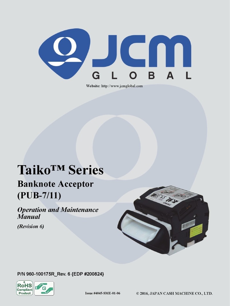
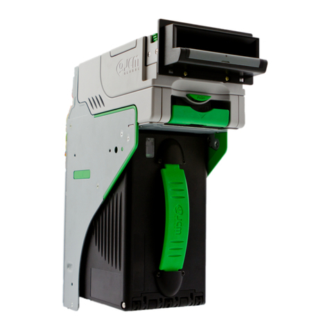
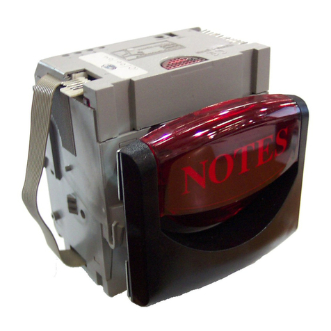
JCM TAIKO User manual

Service Manual
Issue: 06/2008
4045-SME-000E

TAIKO Service Manual
2
Preface
© 2006 Japan Cash Machine Co.Ltd. All rights reserved.
Preface
Thank you for purchasing JCM’s TAIKO Bill Acceptor. Please be sure to read the follow-
ing and any related documents thoroughly to understand the correct operation and features
of this unit.
Note
1. It is forbidden to copy the contents of this manual, in whole or in part, except for the
user’s personal use, without the express permission of Japan Cash Machine Co., Ltd.
2. The information provided in this manual is subject to change without notice.
3. This manual has been written with care and attention to detail; however, should you
find any errors or omissions, please contact Japan Cash machine Co., Ltd. and inform
them of you findings.
4. Please be aware that Japan Cash Machine shall not be held liable by the user for any
damages, losses or third party claims arising from any uses of this product.
5. All Company/Manufacturer names used in this manual are the registered trademarks of
those companies.
Precautions
Machine Design
- We take all possible measures to ensure the quality of this unit. However, performance
degradation or possible short or open circuit faults could occur at the end of a
product’s life. Please ensure safety by sufficiently implementing a fail-safe design.
- Allow sufficient space around the unit to facilitate the collection of banknotes and
cleaning of jams.
Installation
- Do not use the acceptor outside of the operation temperature and humidity ranges
specified in this guide.
- Do not use the acceptor in locations that will obstruct the acceptor’s air holes and
cause the unit to become hot.
- Do not use the acceptor in locations with extreme temperature fluctuations.
- Do not use the acceptor in direct sunlight or incandescent lighting (3000 Lx or greater
at a 15 degrees angle or less).
- Do not use or store the acceptor in locations with high levels of dust.
- The acceptor is for indoor use only; do not use it outside.
- Do not use the acceptor in locations where chemical vapor is present.

3
TAIKO Service Manual
Preface
© 2006 Japan Cash Machine Co.Ltd. All rights reserved.
- When using the acceptor in a location where the air is subject to the car exhaust emis-
sions or cigarette smoke, be sure to clean and maintain the unit at regular intervals.
Wiring
- When installing the TAIKO unit or connecting the wiring harness, make sure that the
power harness from the power terminal.
- When connecting the wiring harness to the TAIKO unit, be sure to confirm the rated
voltage and pin assignments. Failure to do so may result in damage to the unit.
- Be sure to connect the power harness properly. Failure to do so may result in incorrect
input/output due to contact failure.
- Do not pull on the power harness with undue force, as that may cause the harness to
break.
Operation
- Be sure to turn off the power to the TAIKO unit when opening the upper and lower
covers. Failure to do so may result in your fingers becoming caught in the moving
roller.
- Be careful not to get your finger caught when closing the upper cover.
- Do not modify the TAIKO unit. Doing so may damage the unit.
- Do not expose the TAIKO unit to strong impacts or drop the unit as doing so may
damage the unit.
- Do not wipe the TAIKO unit, either outside or inside, with thinner or organic solvent.
- Do not allow moisture or liquid to enter the TAIKO unit.
- Do not store the acceptor outside of the specified storage temperature and humidity
ranges.
- The following banknotes might be not accepted properly by the TAIKO unit or may
cause a jam or damage to the unit.
a. Banknotes with stain, wear, tears or excessive wrinkles, or that are wet or damp.
b. Dog-eared or creased banknotes
c. Banknotes with incorrect cut dimensions or printing displacement
d. Banknotes with oil smear of oil or foreign objects
Disposal
- Disposal of this unit should be accomplished in accordance with your country’s regula-
tions for similar types of industrial waste.

TAIKO Service Manual
4
Preface
© 2006 Japan Cash Machine Co.Ltd. All rights reserved.
Product Configurations
TAIKO unit’s are configured as follows.
[Model] PUB-* [Type] *** - * * * * - **
A B C D E F G
A. Validation Method 7: Optical/Transparency/Reflection
11: Optical/Transparency/Reflection/MAG
B. Country Code ISO based 3-digit codes
C. Faceplate Type 0: Withdout faceplate
1: Acceptable Bill Width Max. 82mm/ Min. 67mm
2: Acceptable Bill Width Max.82mm/ Min. 75mm
3: Acceptable Bill Width Max.82mm/ Min. 70mm
5: Acceptable Bill Width 66mm
D. Optional Unit 0: Without optional unit
1: With interface pin assignment conversion harness
(ccTalk-compatible)
2: ID-001 Interface Type (Upper tray for 16PIN connector)
3: Individual
E. Board Type 1: Standard
2: Interface pin assignment (ccTalk-compatible)
3: Parallel Interface type
F. Operation Code 0: Standard
G. Interface X4: SERIAL(ID-003)/MDB/PULSE/ccTalk
01 : ID-001 (parallel)
Example: PUB-7 EUR-1020-X4
Indicates the TAIKO model Bill Acceptor with Optical/Transparency Reflection
Type, Type 1 faceplate, Euro software, no optional unit, interface pin assignment
(ccTalk-compatible) type board, standard operation code, and an Serial(ID-003)/
MDB/Pulse/ccTalk interface.

5
TAIKO Service Manual
Preface
© 2006 Japan Cash Machine Co.Ltd. All rights reserved.
Package Contents
The following items are contained within the TAIKO Package.
TAIKO unit
Installation Guide
- This unit has been carefully packed, with special attention
taken in regard to quality. However if you happen to find any-
thing damaged of missing, please contact your local distribu-
tor immediately.
TAIKO
Integration
Guide
㪈
ID-001 I/F Harness
(3280-05-100)
* Bandled Item for
Parallel Interface
Specification

TAIKO Service Manual
6
Preface
© 2006 Japan Cash Machine Co.Ltd. All rights reserved.
CE Marking Note
DECLARATION OF CONFORMITY
MANUFACTURER
Name : JAPAN CASH MACHINE CO., LTD.
Address : 3-15, 2-chome, Nishiwaki, Hirano-ku, Osaka, 547-0035 Japan
Phone : +81-6-6703-8405
Fax : +81-6-6704-7843
DETAILS OF PRODUCT : BILL ACCEPTOR
MODEL TYPES : PUB-7, PUB-11
THIS PRODUCT CONFORMS TO THE ESSENTIAL REQURIEMENTS OF :
Electromagnetic Compatibility Directive 89/336/EEC
Amended by 92/31/EEC, 93/68/EEC
Low Voltage Directive 73/23/EEC
Amended by 93/68/EEC
and is supported by the following applicable standards
EN61000-6-1 : 2001
EN61000-4-2 : 1995+A1 : 1998+A2 : 2001
EN61000-4-3 : 2002+A1 : 2002
EN61000-4-8 : 1993+A1 : 2001
EN61000-6-3 : 2001
EN55022 : 1994+A1 : 1995+A2 : 1997(ClassB)
EN60950-1 : 2001+A11 : 2004 First Edition
Authorized signatory on behalf of the responsible person
Name/Signature : Tatsuya Urata/
Date : December 1, 2006
Position : Director and executive officer, general manager manufacturing division
Germany Office
Address : Mundelheimer Weg 60, 40472 Dusseldorf, Germany
Phone : +49-211-530645-0
Fax : +49-211-530645-65
Tatsuya Urata

7
TAIKO Service Manual
Preface
© 2006 Japan Cash Machine Co.Ltd. All rights reserved.
Documentation Conventions
The list below describes the documentation convertions used in this manual.
Icon/Mark Descriptions
This icon indecates important information or procedures that must be
followed for correct and risk-free unit operation.
This icon indicates useful or recommended supplemental
information.
1. 2…. This indicates steps in a procedure. Be sure to perform these steps
in the order given.
See=> This indicates related information to refer.
* This indicates useful or important supplemental inforamation
RoHS Compliance
The TAIKO (PUB-7/PUB-11) is a RoHS Compliant products. The following six kind of
hazardous substances restricted by RoHS are NOT contained in the TAIKO unit.
Restricted Hazardous Substances
- Plumbum
- Mercury
- Cadmium
- Chromium Hexavalent
- PBB
- PBDE
- All brand names and product names are trademarks or regis-
tered trademarks of their respective companies.

TAIKO Service Manual
8
Preface
© 2006 Japan Cash Machine Co.Ltd. All rights reserved.
Table of Contents
Preface
Preface ............................................................................................................................. 2
Note .................................................................................................................................. 2
Precautions...................................................................................................................... 2
Product Configurations ................................................................................................. 4
Package Contents ........................................................................................................... 5
CE Marking Note ........................................................................................................... 6
RoHS Compliance .......................................................................................................... 6
Documentation Conventions ......................................................................................... 6
Chapter 1 Introduction
1-1. Main Features.......................................................................................................1-2
1-2. Prior to Use ...........................................................................................................1-3
1-3.Component Names ................................................................................................1-4
1-4. System Configuration ..........................................................................................1-5
1-5. Operation Flowchart............................................................................................1-6
Chapter 2 Specifications
2-1. Specifications ........................................................................................................2-2
2-1-1. Basic Technical Specifications ......................................................................................... 2-2
2-1-2. Electrical Specifications ................................................................................................... 2-2
2-1-3. Environmental Specifications.......................................................................................... 2-2
2-1-4. Structural Specifications.................................................................................................. 2-3
2-2. Connector..............................................................................................................2-4
2-2-1. Interface Connector
X4: ID-003 (serial)/ MDB/ Pulse/ ccTalk specification ................................................... 2-4
2-2-1-1. Interface Connector Pin Assignments
X4: ID-003 (serial)/ MDB/ Pulse/ ccTalk specification .......................................... 2-4
2-2-2. Interface Connector
01: ID-001 (parallel) specification ................................................................................... 2-5
2-2-2-1. Interface Connector Pin Assignments
01: ID-001 (parallel) specification ........................................................................... 2-6
2-3. Interface Circuit ...................................................................................................2-7
2-3-1. ccTalk Interface Circuit ................................................................................................... 2-7
2-3-2. ID-003 (serial)/ MDB Interface4 Circuit ........................................................................ 2-8
2-3-3. Pulse Interface Circuit ..................................................................................................... 2-9
2-3-4. ID-001 (parallel) Interface4 Circuit.............................................................................. 2-10

9
TAIKO Service Manual
Preface
© 2006 Japan Cash Machine Co.Ltd. All rights reserved.
2-4. External Dimensions .......................................................................................... 2-11
2-4-1. When installing the Type 1/ Type 2/ Type 3 faceplate with TAIKO unit................... 2-11
2-4-2. When installing the Type 5 faceplate with TAIKO unit ............................................. 2-12
2-5. DIP Switch Setting .............................................................................................2-13
2-5-1. Basic Settings
X4: ID-003 (serial)/ MDB/ Pulse/ ccTalk specification ................................................. 2-14
2-5-2. Basic Settings
01 : ID-001 (parallel) specification ................................................................................. 2-14
2-6-3. Special Settings ............................................................................................................... 2-14
Chapter 3 Installation / Operation
3-1. Installation/Removal ............................................................................................ 3-2
3-2. Wiring....................................................................................................................3-5
3-2-1. Recommended Parts ........................................................................................................ 3-5
3-2-1-1. Reccomended Parts
X4: ID-003 (serial)/ MDB/ Pulse/ ccTalk specification .......................................... 3-5
3-2-1-2. Reccomended Parts
01 : ID-001 (parallel) specification .......................................................................... 3-5
3-2-2. Wiring Procedure ............................................................................................................. 3-6
3-3. Clearing Bill JAM ................................................................................................3-7
Chapter 4 Download / Adjustment
4-1. Download ..............................................................................................................4-2
4-1-1. Requirements .................................................................................................................... 4-2
4-1-2. Connecting Procecedure .................................................................................................. 4-3
4-1-3. Download Procedure ........................................................................................................ 4-4
4-1-4. Writing Serial No.............................................................................................................. 4-5
4-2. Adjustment............................................................................................................4-6
4-2-1. Requirements .................................................................................................................... 4-6
4-2-2. Adjustment Procedure ..................................................................................................... 4-6
4-3. Palm.......................................................................................................................4-8
4-3-1. Requirement...................................................................................................................... 4-8
4-3-2. Installing File Converter (PdbConvEN.exe) .................................................................. 4-8
4-3-3. Converting Software Program ....................................................................................... 4-9
4-3-4. Download Procedure ...................................................................................................... 4-10
4-4. Cloning ................................................................................................................ 4-11
4-4-1. Required Items ............................................................................................................... 4-11
4-4-2. Cloning Procedures ........................................................................................................ 4-11
Chapter 5 Trouble Shooting / Maintenance
5-1. Error Code ............................................................................................................5-2
5-1-1. Error Code ........................................................................................................................ 5-2
TAIKO Service Manual
10
Preface
© 2006 Japan Cash Machine Co.Ltd. All rights reserved.
5-2. Trouble Shooting ..................................................................................................5-2
5-2-1. General Troubles .............................................................................................................. 5-2
5-2-2. Adjustment Troubles ........................................................................................................ 5-4
5-2-3. Communication Troubles ................................................................................................ 5-5
5-3. Test Mode (Diagnostics).......................................................................................5-6
5-3-1. DIP Switch Setting List .................................................................................................... 5-6
5-3-2. DIP Switch Test Procedure .............................................................................................. 5-6
5-3-3. Transport Motor Forward Rotation Test Procedure .................................................... 5-6
5-3-4. Transport Motor Reverse Rotation Test Procedure...................................................... 5-7
5-3-5. Aging Procedure ............................................................................................................... 5-7
5-3-6. Solenoid Test Procedure................................................................................................... 5-8
5-3-7. Accepting Test Procedure ................................................................................................ 5-8
5-3-8. Entrance Flapper Test Procedure ................................................................................... 5-9
5-3-9. Exit Flapper Test Procedure ........................................................................................... 5-9
5-4. Cleaning ..............................................................................................................5-10
5-5. Maintenance Tool List ....................................................................................... 5-11
5-6. Wiring Diagram .................................................................................................5-12
5-5-1. PUB-7 Wiring Diagram ................................................................................................. 5-12
5-5-2. PUB-11 Wiring Diagram................................................................................................ 5-13
5-7. Product Support .................................................................................................5-14
Chapter 6 Replacement
6-1. Replacement of Faceplate Guide ........................................................................6-2
6-2. Replacement of CPU Board ................................................................................6-3
6-3. Replacement of MAG Board...............................................................................6-4
6-4. Replacement of Sensor Board .............................................................................6-5
6-5. Replacement of Encoder Board/Motor Unit......................................................6-9
6-6. Replacement of Solenoid ...................................................................................6-10
Chapter 7 Exploded View / Parts List
7-1. Entire Unit & Option ...........................................................................................7-2
7-1-1. Entire Unit & Option Exploded View ............................................................................ 7-2
7-1-2. Entire Unit & Option Parts List ..................................................................................... 7-3
7-2. TAIKO (PUB-7/PUB-11) Unit .............................................................................7-4
7-2-1. TAIKO (PUB-7/PUB-11) Unit Exploded View .............................................................. 7-4
7-2-2. TAIKO (PUB-7/PUB-11) Unit Parts List ....................................................................... 7-5
7-3. Bezal Unit..............................................................................................................7-7
7-3-1. Bezel Unit Exploded View................................................................................................ 7-7
7-3-2. Bezel Unit Parts List......................................................................................................... 7-8

Integration Guide
Bill Acceptor

2
Table of Contents
1. Precautions .......................................................................................................................... 4
1-1. Machine Design ........................................................................................................... 4
1-2. Installation ................................................................................................................... 4
1-3. Wiring .......................................................................................................................... 4
1-4. Operation ..................................................................................................................... 4
1-5. Disposal ....................................................................................................................... 4
2. Package Contents ................................................................................................................ 5
3. Product Configurations .......................................................................................................5
4. CE Marking ......................................................................................................................... 6
5. RoHS Compliance ............................................................................................................... 7
6. Names of Parts .................................................................................................................... 7
7. Product Specifications ......................................................................................................... 8
7-1. General Specifications ................................................................................................. 8
7-1-1. Basic Specifications .......................................................................................... 8
7-1-2. Electrical Specifications .................................................................................... 8
7-1-3. Environmental Specifications ............................................................................ 8
7-1-4. Installation Specifications ................................................................................. 9
7-2. Connector ..................................................................................................................... 9
7-2-1. Interface Connector
X4:Serial(ID-003)/MDB/Pulse/ccTalk Specification .................................. 9
7-2-1-1.Interface Connector Pin Assignment
X4:Serial(ID-003)/MDB/Pulse/ccTalk Specification ................................ 10
7-2-2. Interface Connector
01:Parallel(ID-001) Specification ............................................................... 11
7-2-2-1. Interface Connector Pin Assignment
01:Parallel(ID-001) Specification ............................................................... 11
7-3. Interface Circuit ......................................................................................................... 12
7-3-1. ccTalk Interface Circuit ................................................................................... 12
7-3-2. Serial(ID-003)/MDB Interface Circuit ............................................................ 13
7-3-3. Pulse Interface Circuit ..................................................................................... 14
7-3-4. Parallel(ID-001) Interface Circuit .................................................................. 15
7-4. External Dimensions .................................................................................................. 16
7-4-1. External Dimensions when installing Type1/Type2/Type3 Faceplate ............. 16
7-4-2. External Dimensions when installing Type5 Faceplate ................................... 17
7-5. DIP Switch Settings ................................................................................................... 18
7-5-1. Basic Settings
X4:Serial(ID-003)/MDB/Pulse/ccTalk Specification ................................ 18
7-5-1-1. Denomination Setting Mode ....................................................................... 19
7-5-1-2. Encryption Code Initializing Setting Mode ................................................ 19
7-5-2. Basic Settings
01:Parallel(ID-001) Specification .............................................................. 20
7-5-3. LED Pattern Setting Mode ......................................................................... 20

3
Table of Contents
8. Installation/Removal .........................................................................................................21
9. Wiring ................................................................................................................................ 24
9-1. Recommended Parts .................................................................................................. 24
9-1-1. Recommended Parts X4:Serial(ID-003)/MDB/Pulse/ccTalk Specification ....... 24
9-1-2. Recommended Parts 01:Parallel(ID-001) Specification ..................................... 24
9-2. Wiring Procedure ....................................................................................................... 25
10. Clearing a Banknote Jam ................................................................................................. 26
11. Error Codes ...................................................................................................................... 27
12. Cleaning .......................................................................................................................... 27
13. Product Support ............................................................................................................... 28

4
1. Precautions
Thank you for purchasing JCM’s TAIKO Bill Acceptor. Please be sure to read the following and
any related documents thoroughly to understand the correct operation and features of this unit.
1-1. Machine Design
- We take all possible measures to ensure the quality of this unit. However, performance degrada-
tion or possible short or open circuit faults could occur at the end of a product’s life. Please
ensure safety by sufficiently implementing a fail-safe design.
- Allow sufficient space around the unit to facilitate the collection of banknotes and the clearing of
jams.
1-2. Installation
- Do not use the acceptor outside of the operation temperature and humidity ranges specified in
this guide.
- Do not use the acceptor in location that will obstruct the acceptor’s air holes and cause the unit to
become hot.
- Do not us the acceptor in locations with extreme temperature fluctuations.
- Do not use the acceptor in direct sunlight or incandescent lighting (3000Lx or greater at a 15-
degree angle or less).
- Do not use or store the acceptor in location with high levels of dust.
- The acceptor is for indoor use only; do not use it outside.
- Do not use the acceptor in locations where chemical vapor is present.
- When using the acceptor in a location where the air is subject to the car exhaust emissions or
cigarette smoke, be sure to clean and maintain the unit at regular intervals.
1-3. Wiring
- When installing the TAIKO unit or connecting the wiring harness, make sure that the power
harness is unplugged from the power terminal to avoid unit damage.
- When connecting the wiring harness to TAIKO unit, be sure to confirm the rated voltage and pin
assignments. Failure to do so may result in damage to the unit.
- Be sure to connect the power harness properly. Failure to do so may result in incorrect input/
output due to contact failure.
- Do not pull on the power harness with undue force, as that may cause the harness to break.
1-4. Operation
- Be sure to turn off the power to the TAIKO unit when opening the upper and lower lid. Failure to
do so may result in your fingers becoming caught in the moving roller.
- Be careful not to get your finger caught when closing the upper lid.
- Do not modify the TAIKO unit. Doing so may damage the unit.
- Do not expose the TAIKO unit to strong impacts or drop the unit as doing so may damage the
unit.
- Do not wipe the TAIKO unit, either outside or inside, with thinner or organic solvent.
- Do not allow moisture or liquid to enter the TAIKO unit.
- Do not store the acceptor outside of the specified storage temperature and humidity ranges.
- The following banknotes might be not accepted properly by TAIKO unit or may cause a jam or
damage to the unit.
a. Banknotes with stains, wear, tears or excessive wrinkles, or that are wet or damp.
b. Dog-eared or creased banknotes
c. Banknotes with incorrect cut dimensions or printing displacement
d. Banknotes with oil smears or foreign objects
1-5. Disposal
- Disposal of this unit should be accomplished in accordance with your country’s regulations for
similar types of industrial waste.

5
2. Package Contents
The following items are contained within the TAIKO packaging.
TAIKO unit
Installation Guide
ID-001 I/F Harness
<This guide> (3280-05-100)
* The item is packaged
for Parallel Interface
Specification only.
- This unit has been carefully packed, with special attention taken in re-
gard to quality. However if you happen to find anything damaged or
missing, please contact your local distributor immediately.
3. Product Configurations
TAIKO units are configured as follows.
[Model] PUB-* [Type] *** - * * * * - **
A B C D E F G
A.Validation Method 7: Optical/Transparency/Reflection
11: Optical/Transparency/Reflection/MAG
B. Country Code ISO 3166 based 3-digit codes
C. Faceplate Type 0: Without faceplate
1: Bill Width Min.68mm/Max.82mm
2: Bill Width Min.76mm/Max.82mm
3: Bill Width Min.70mm/Max.82mm
5: Bill Width 66mm
D. Optional Unit 0: Without optional unit
1: With interface pin assignment conversion adapter harness
(ccTalk-compatible)
2:Parallel(ID-001) Interface Type (Upper Tray dedicated 16PIN
connecter)
3:Individual Specification
E. Board Type 1: Standard
2: Interface pin assignment (ccTalk compatible)
3:Parallel Interface Type
F. Operation Code 0: Standard
1:Individual Specification
G. Interface X4: Serial(ID-003)/MDB/Pulse/ccTalk
01:Parallel(ID-001)
Installation
Guide
㪈

6
4. CE Marking
DECLARATION OF CONFORMITY
MANUFACTURER
Name : JAPAN CASH MACHINE CO., LTD.
Address : 3-15, 2-chome, Nishiwaki, Hirano-ku, Osaka, 547-0035 Japan
Phone : +81-6-6703-8405
Fax : +81-6-6704-7843
DETAILS OF PRODUCT : BILL ACCEPTOR
MODEL TYPES : PUB-7, PUB-11
THIS PRODUCT CONFORMS TO THE ESSENTIALREQURIEMENTS OF :
Electromagnetic Compatibility Directive 89/336/EEC
Amended by 92/31/EEC, 93/68/EEC
Low Voltage Directive 73/23/EEC
Amended by 93/68/EEC
and is supported by the following applicable standards
EN61000-6-1 : 2001
EN61000-4-2 : 1995+A1 : 1998+A2 : 2001
EN61000-4-3 : 2002+A1 : 2002
EN61000-4-8 : 1993+A1 : 2001
EN61000-6-3 : 2001
EN55022 : 1994+A1 : 1995+A2 : 1997(ClassB)
EN60950-1 : 2001+A11 : 2004 First Edition
Authorized signatory on behalf of the responsible person
Name/Signature: Tatsuya Urata/
Date : December 1, 2006
Position : Director and executive officer, general manager manufacturing division
Germany Office
Address : Mundelheimer Weg 60, 40472 Dusseldorf, Germany
Phone : +49-211-530645-0
Fax : +49-211-530645-65
Tatsuya Urata
Example: PUB-7 EUR-1020-X4
Indicates the TAIKO model with optical/transparency/reflection validation method,
faceplate type 1, euro software, no optional unit, interface pin assignment (ccTalk
compatible) type board, standard operation code and an Serial(ID-003)/MDB/Pulse/
ccTlak interface.

7
6. Names of Parts
The name of parts for the TAIKO unit are as follows.
A. Faceplate B. LED lamp
C. Upper lid D. Lower lid
E. Lower lid lock release button F. Bill insertion slot
G. Bill ejection slot H. Interface connector
I. Maintenance connector J. Faceplate installation guide pin
K. Upper lid open/close button L. Optional connector(No Optional Connector for
M. DIP switches Parallel(ID-001) Interface Specification.)
Top
Right
Bottom
Rear
Front
C
G
L
D
KM
H
A
B
F
Left
J
I
E
J
5. RoHS Compliance
The TAIKO unit is a RoHS Compliant products. The following six kind of hazardous substances
fulfil the safety limit of the standard restricted by RoHS compliance.
Restricted Hazardous Substances
- Plumbum
- Mercury
- Cadmium
-Hexavalent Chromium
- PBB
- PBDE

8
Power Supply Voltage 12V ±5% DC
Rated Power Consumption
Standby: Approx. 0.1 A
Operation: Approx. 0.8 A
Max.: Approx. 1.4 A (Max. 300 ms)
7. Product Specifications
7-1. General Specifications
7-1-1. Basic Specifications
Acceptable Banknote Size Length: 120 mm to 160 mm
Width: 62 mm to 82 mm
Insertion Direction *1 4-way
Acceptance Rate *1 95% or higher
Validation Method PUB-7: Optical/T ransparency/Reflection
PUB-11: Optical/T ransparency/Reflection/MAG
Anti-fishing Mechanism Lever and optical sensor combination
Interface X4:Serial(ID-003)/MDB/Pulse/ccTalk *2
01:Parallel(ID-001)
Escrow 1 banknote
LED LED lamp (upper portion of faceplate)
Full-color lightning (gradation/solid)
*1 May differ depending on the software for your country. For details, refer to the
Software Information Sheet.
*2 Can be selected using the DIP switches. => 7-5-1.Refer to DIP switch settings.
(No DIP switch settings for Parallel(ID-001) Interface Specification.)
7-1-3. Environmental Specifications
*1 The overall operation temperature and humidity range is as follows.
Operation T emperature *1 5oC t o 50oC
Storage Temperature -20oC t o 6 0oC
Operation Humidity *1 20%RH to 85%RH (No condensation)
Storage Humidity 20%RH to 85%RH (No condensation)
Ligh t Dist urbance
Avoid direct sunlight
Interior lighting must be incandescent lamp
Angle: 15 degrees or more
Illumination: 3000Lx or less
Installation For indoor use only
Ambient temperature
humidity range
35
o
C / 85RH%
50
o
C / 40RH%
(RH%)
100
90
80
70
60
50
40
30
20
10
0
0 5 10 15 20 25 30 35 40 45 50 55 60 (
o
C)
7-1-2. Electrical Specifications

9
91
2
10
7-2. Connector
7-2-1. Interface Connector
X4:Serial(ID-003)/MDB/Pulse/ccTalk Specification
The following diagram is the interface connector as viewed from the acceptor side or from a
relay board.
Box Type Plug
XG4C-1034 (Omron)
- If a relay board is attached to the TAIKO unit, do not attempt to re-
move it.
7-1-4. Installation Specifications
Mounting *1 Door and Horizontal Mounting (No vibration)
Weight Approx. 0.6 kg
External Dimensions
When installing Type 1/2/3 faceplate:
124mm (W) x 88mm (H) x 145.2mm (D)
When installing Type 5 faceplate:
124mm (W) x 88mm (H) x 143mm(D)
Cashbox *2 Supplied by the customer
*1 Allow 100 mm above the unit to open the lid for removal of the unit from the
faceplate
*2 The cashbox must be 100 mm or more in depth from the bottom of the TAIKO
unit, 200 mm or more in depth from the rear of the unit and 100 mm or more in
width. Both sides of the cashbox must be higher than the position of the bill
ejection slot.
Depth from rear of unit
200 mm or more
Cashbox
100 mm or more
Depth from bottom of unit
100 mm or more
Width
100 mm or more
Position of
bill ejection slo
t
Side Rear

10
*1 Conditions for the I/O (Input/Output) column are from the acceptor side.
Pin No. Signal Name I/O *1 Function
1 ccTalk+ IN/OUT ccT alk Send/Receive Line
2 NC - Not Connected
3 NC - Not Connected
4 NC - Not Connected
5 NC - Not Connected
6 NC - Not Connected
7 VCC - 12V DC Power Supply
8 VSS - Power Supply GND
9 NC - Not Connected
10 NC - Not Connected
ccTalk Communication
7-2-1-1. Interface Connector Pin Assignment
X4:Serial(ID-003)/MDB/Pulse/ccTalk Specification
- The following pin assignment is for TAIKO units with a blue JCM logo
label. If the logo is black, the pin assignment may differ. For details,
contact JCM.
Blue
Black
Pin No. Signal Name I/O *1 Function
1 NC - Not Connected
2 NC - Not Connected
3 RXD-
4RXD+
5 TXD-
6TXD+
7 VCC - 12V DC Power Supply
8 VSS - P o wer Sup p ly GND
9 NC - Not Connected
10 NC - Not Connected
IN
OUT
Data Receive Line
(Active when current is applied)
Data Send Line
(Active when current is applied)
Serial(ID-003)/MDB Communication
*1 Conditions for the I/O (Input/Output) column are from the acceptor side.
Table of contents
Other JCM Bank Note Validator manuals