JCM TBV Series Installation guide

1
Part No. 960-100941R_Rev. A
October, 2016
®
© 2016 JCM American Corporation
Phone (800) 683-7248
(702) 651-0000
Fax (702) 651-0214
E-mail [email protected]
www.jcmglobal.com
JCM®TRAINING
OVERVIEW
TBV™Series
TBV Transaction Based Validator

Part No. 960-100941R_Rev. A © 2016 JCM American Corporation
2
TBV Transaction Based Validator JCM® Training Overview October, 2016
Page
TBV™Transaction Based Validator
Table of Contents
Overview ................................................................................. 3
TBV Transaction Based Validator Unit ................................... 3
Component Locations ............................................................. 4
DIP Switch Settings ................................................................ 5
Cleaning Procedures .............................................................. 8
JCM Tool Suite™ Overview .................................................. 10
Firmware Download Procedure .............................................11
Calibration ............................................................................ 12
Using the Calibration Program ...............................................................12
Validation Sensor Calibration .................................................................12
Positioning Sensor Calibration ...............................................................13
Performance Testing Procedures ......................................... 15
Operation Tests ..................................................................... 16
Acceptance Tests ...................................................................................16
Motor Tests .............................................................................................19
Motor Speed Test ...................................................................................21
Device Function Test...............................................................................21
Sensor On/Off Test ............................................................... 22
DIP Switch Test .................................................................... 25
TBV Error Code Tables ......................................................... 26
Banknote Jam Error Codes.....................................................................26
Operational Error Codes.........................................................................27
ICB Error Codes......................................................................................30
Reject Error Codes..................................................................................31
Ticket Reject Error Codes.......................................................................33
Calibration Errors ...................................................................................35
TBV Maintenance Equipment ............................................... 37
Maintenance Equipment Parts List ....................................... 38
Part No. 960-100941R_Rev. A © 2016 JCM American Corporation
3
TBV Transaction Based Validator JCM® Training Overview October, 2016
OVERVIEW
This training course addresses the following JCM TBV™device versions:
TBV T
RANSACTION
B
ASED
V
ALIDATOR
U
NIT
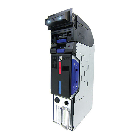
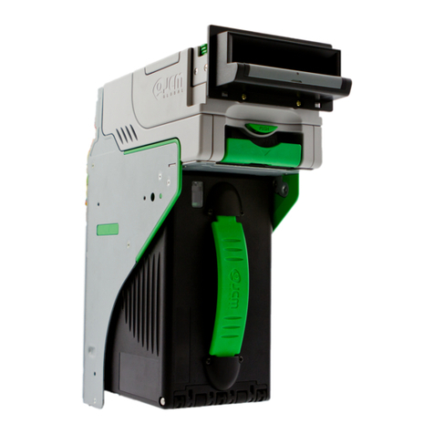
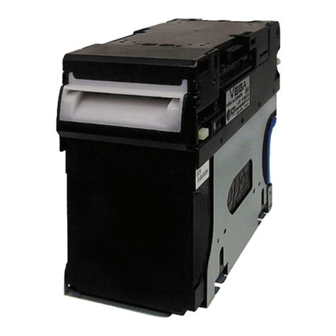
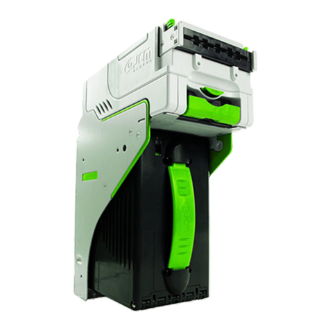
Figure 1 illustrates the TBV FSH, FLD, GSH and GLD Unit Versions (ASH Unit
not shown).
Table 1 TBV Versions
Device Version Description
TBV-100 FSH BNF, Horizontal Stack Cash Box, Centering Path
TBV-101 FSH BNF, Horizontal Stack Cash Box, Fixed Path
TBV-100 FLD BNF, No Cash Box, Centering Path
TBV-101 FLD BNF, No Cash Box, Fixed Path
TBV-100 GLD Single note, Gated Bezel, No Cash Box, Centering Path
TBV-101 GSH Single note, Gated Bezel, Horizontal Stack Cash Box, Fixed Path
TBV-101 ASH Single Note, JCM Standard Bezel, Horizontal Stack Cash Box, Fixed Path
Figure 1 Available TBV Unit Versions
TBV (GLD Version) TBV (GSH Version)
TBV (FLD Version)
TBV
(FSH Version)

Part No. 960-100941R_Rev. A © 2016 JCM American Corporation
4
October, 2016 JCM® Training Overview TBV Transaction Based Validator
COMPONENT LOCATIONS
Figure 2 illustrates the TBV component names and locations.
Frame
Section
Transport
Section
Frame Section Top
BNF
Section
Bezel
Section
1
2
3
4
5
6
7
8
9
10
11
12
13
14
16
15
17
18
19 20 21 22
23
24
25
26
27
28 29 30 31 32
33
34
Figure 2 TBV Component Names
1. Interface Connector
2. Cash Box Lock Lever (Back Side)
3. ICB Sensor Lens Assembly (Option)
4. ICB Power Switch (DS7) (Option)
5. Transport Signal Connector
6. Transport Section Rear Guide Latch
7. Centering Release Port (Back Side)
8. Transport Section Front Guide Release Latch
9. Transport Section Release Lever
10.LED Indicator (Green/Yellow/Red)
11. Return Path Open/Close Cover
12.BNF Guide Latch
13.Pusher Plate
14.BNF LED Indicator (Full Color Range)
15.Bezel (Standard)
16.BNF/Transport Section Release Lever
17.USB Connector Port
18.BNF Connector (Back Side)
19.Transport USB Connector Port
20.Denomination INHIBIT/ACCEPT Switches
(DS3 [Set identical as DS1])
21.Bezel LED Indicator Connector
22.Transport Signal Connector
23.Cash Box Release Lever
24.Cash Box Handle
25.Thumb Twist Lock Knob
(replaced by Optional Lock)
26.Cash Box Seal Assembly (Option)
27.Cash Box Lock Lever (Back Side)
28.Denomination INHIBIT/ACCEPT Switches
(DS1 [Set identical as DS3])
29.Set BNF Buzzer Volume Switches (DS2)
30.TBV Centering Mechanism ON/OFF & Select
Communication Interface Switches (DS4)
31.ICB Sensor
32.TBV Photo-Coupler/RS232 Interface
Selection Switch (DS5)
33.TBV Option Memory Selection Switches
(DS6)
34.Lock & Key Assembly (Option)

Part No. 960-100941R_Rev. A © 2016 JCM American Corporation
5
Lecture Notes
TBV Transaction Based Validator JCM® Training Overview October, 2016
DIP SWITCH SETTINGS
Table 2 lists the default TBV DIP Switch Configuration for DS1 on the Bulk
Note Feed (BNF) Unit, and DS3 on the Transport Unit.
Table 3 lists the BNF Unit Buzzer Volume Switch settings for DS2.
Table 2 BNF Set Vend Denomination Switch DS1/DS3 Settings
Switch No. Switch ON Switch OFF
1 VEND 1 INHIBIT VEND 1 ACCEPT
2 VEND 2 INHIBIT VEND 2 ACCEPT
3 VEND 3 INHIBIT VEND 3 ACCEPT
4 VEND 4 INHIBIT VEND 4 ACCEPT
5 VEND 5 INHIBIT VEND 5 ACCEPT
6 VEND 6 INHIBIT VEND 6 ACCEPT
7 VEND 7 INHIBIT VEND 7 ACCEPT
8 Test Mode OFF (Fixed)
Table 3 BNF Buzzer Volume Switch DS2 Settings
Switch
No. Switch ON Switch OFF
1N/A*
* Not Applicable (N/A). Never Switched to ON.
OFF (Fixed)
2 Performance Buzzer ON Performance Buzzer OFF
3 ON Fixed N/A
4 N/A* OFF (Fixed)
NOTE: If the BNF Unit is installed, use DS1 (DS3 settings have no effect).
If the BNF Unit is NOT installed (single note configuration), use DS3.
ON
OFF DS1/DS3
OFF DS2
ON

Part No. 960-100941R_Rev. A © 2016 JCM American Corporation
6
October, 2016 JCM® Training Overview TBV Transaction Based Validator
Lecture Notes
Table 4 lists the TBV Centering Mechanism and COM Interface Switch set-
tings for DS4.
Table 5 lists the TBV Photo-Coupler/RS-232 Interface Selection Switch setting
for DS5.
Table 4 TBV Centering Mechanism &
Select Com Interface Switch DS4 Settings
Switch No. Switch ON Switch OFF
1 Fixed Version Centering Version
2Barcode Coupon
Single Read*
* When using the “Single Read” Barcode Coupon setting, its Checksum may have
to be changed to improve reading accuracy. The “Double Read” setting however,
has a higher reliability and read accuracy by the TBV Validation System.
Barcode Coupon
Double Read*
3†
† Match each setting to equal the setting of DIP Switch DS5 Switch #1.
4†
Table 5 TBV Photo-Coupler/RS232 Interface Selection Switch DS5 Setting
Switch No. Switch ON Switch OFF
1*
* Match each setting to DIP Switch DS4 Switches #3 & #4.
Photo-Coupler RS232
OFF DS4
ON
I/F Selection Switch #3 Switch #4
RS232 OFF OFF
Photo-Coupler ON OFF
ccTalk OFF ON
ccTalk with Encryption ON ON
RS232
Photo-Coupler
DS5 ON
OFF

Part No. 960-100941R_Rev. A © 2016 JCM American Corporation
7
TBV Transaction Based Validator JCM® Training Overview October, 2016
Lecture Notes
Table 6 lists the TBV Optional Memory Selection Switch settings for DS6.
Table 7 lists the TBV Intelligent Cash Box (ICB) DS7 Settings.
Table 6 TBV Option Memory Selection Switch DS6 Settings
Switch No. Switch ON Switch OFF
1N/A*
* Not Applicable (N/A). Never Switched to ON.
OFF (Fixed)
2 N/A* OFF (Fixed)
Table 7 TBV ICB Cash Box DS7 Settings
Switch No. Switch ON Switch OFF
1 ICB ON ICB OFF*
* Initial Switch setting is OFF. When using the ICB, turn the ICB Switch
located on the Intelligent Cash Box side to ON.
ON
OFF DS6
NOTE: DS7 is on the Cash Box if an ICB Module is installed.
ICB Disable
ICB Enable
DS7 ON
OFF

Part No. 960-100941R_Rev. A © 2016 JCM American Corporation
8
October, 2016 JCM® Training Overview TBV Transaction Based Validator
CLEANING PROCEDURES
To clean the TBV Unit, gently wipe the Sensors, Rollers and Belts using a
clean, dry (or slightly damped with soap solution) lint-free Microfiber cloth.
Sensor and Roller Cleaning Procedure
1. Turn the TBV Unit power OFF.
2. Remove the TBV Unit from the Host Machine.
3. Open the TBV Unit, BNF, Transport, and Validation sections.
4. Clean the Lens of each Sensor. Refer to Figure 3 for the TBV Sensor Locations
and Table 8 for each Sensor’s cleaning method.
NOTE: When cleaning the TBV Unit, DO NOT use alcohol, solvents, citrus-based
cleaners or scouring agents. These items may cause damage to the Sensors or
Rollers. Use only a mild, non-abrasive detergent or cleaning solution.
1
2
3
4810 11
9
6
5
712
13 18
17
14 16
15 20
19
21
22
Validation Section
Transport Section
(Upper Door Open)
BNF Section
(Upper Portion Open)
(Lower End Open)
23
31
32
33 34
Cash Box Frame Section
24
Figure 3 TBV Sensor and Roller Cleaning Locations
2526 27
2829
30

Part No. 960-100941R_Rev. A © 2016 JCM American Corporation
9
October, 2016 JCM® Training Overview TBV Transaction Based Validator
Table 8 TBV Sensor/Roller Types and Cleaning Methods
Symbol Sensor/Roller Type Cleaning Method
1 Transport Entrance Sensor Prism
Wipe clean using a soft, slightly
damp, lint-free Microfiber cloth*
* Wipe and clean all Rollers and the GREEN Colored Belts shown in Figure 3 using a soft, lint-free Microfiber cloth.
2 Centering Sensor
3 Side Sensor
4 Transport Entrance Sensor
5 Centering Sensor Prism
6 Bar Sensor
7 Box Near Full Sensor
8 Box Full Sensor
9 Feed Out Sensor Prism
10 UV Sensor
11 Magnetic Sensor
12 Feed Out Sensor
13 Pusher Plate Home Position Sensor
14 Box Lock Sensor
15 ICB
16 Pusher Mechanism Home Position Sensor
17 Box Sensor
18 Box Feed Out Sensor
19 Line Sensor
20 UV Sensor
21 BNF Reject Sensor
22 BNF Assignation Sensor
23 BNF Entrance Sensor
24 Pusher Plate Home Position Sensor Prism
25 ICB
26 Box Sensor Prism
27 Box Feed Out Sensor Prism
28 Pusher Mechanism Home Position Sensor Prism
29 Box Near Full Sensor Prism
30 Box Full Sensor Prism
31 Cash Box Lock Sensor Prism
32 Retard Roller Wipe clean using a damp, lint-
free Microfiber cloth†
† When cleaning the Retard Roller, Pick Up Roller, and Feed Roller, use a lint-free Microfiber cloth slightly dampened
with water.
33 Pick Up Roller
34 Feed Roller
NOTE: If Sensor Lenses or Prisms become exposed to water, wipe them dry
IMMEDIATELY using a soft, dry lint-free Microfiber cloth. Then allow them to air
dry for a sufficient amount of time to allow maximum evaporation.

Part No. 960-100941R_Rev. A © 2016 JCM American Corporation
10
October, 2016 JCM® Training Overview TBV Transaction Based Validator
JCM TOOL SUITE™OVERVIEW
The JCM Tool Suite™Standard Edition Software Program supports the follow-
ing Operational Modes and User-selectable Functions (accessible by clicking
the Service Mode drop-down menu as shown in Figure 4):
To use the JCM Tool Suite Software Application:
1. Connect a standard USB Type A-to-Mini B cable from the PC’s USB Port to the
TBV Unit.
2. Apply electrical power to the TBV Unit.
3. Launch the JCM Tool Suite Software Application.
The Main Screen will be displayed (Figure 4).
Table 9 JCM Tool Suite Operational Modes and Functions
Service Mode Functions
Normal (Operational) Mode
(All DS1/DS3 DIP Switches OFF)
(
Download
Statistics
Event Log View
Test Mode*
(DS1/DS3 DIP Switch 8 ON)
* In Test Mode, Bezel LED flashes WHITE.
Download
Statistics
Sensor Adjustment
Performance Test
Event Log View
NOTE: All Diagnostic Tests can be performed by specifying various DIP Switch
settings. Refer to Section 6 of the JCM Global®TBV®Series Transaction Based
Validator Operation and Maintenance Manual (P/N 960-100926R) for information
on setting DIP Switches for testing purposes.
Figure 4 JCM Tool Suite Main Screen

Part No. 960-100941R_Rev. A © 2016 JCM American Corporation
11
October, 2016 JCM® Training Overview TBV Transaction Based Validator
FIRMWARE DOWNLOAD PROCEDURE
To download Firmware to the TBV Unit, proceed as follows:
1. Click on the Service Mode drop down menu, then select Download.
The JCM Downloader Suite Edition screen will appear (Figure 5).
2. Click the “Browse”Screen Button and select the file to be downloaded.
Then click the Open Screen button that appears.
3. The JCM Downloader Suite Edition screen will reappear (Figure 5). Click the
“Download”Screen Button to begin downloading the Firmware.
4. Verify the Host CRC (Cyclic Redundancy Check) (Figure 5 a) and the Device
CRC (Figure 5 b) Checksum values are identical.
5. Disconnect the USB Type A-to-Mini B cable from the PC’s USB Port and the
TBV Unit.
6. Reset electrical power on the TBV Unit.
This completes the Firmware Download Procedure.
NOTE: A BLUE-colored Barograph will display the Download progression.
When downloading is complete, the following message is displayed (Figure 5):
Download Success. Reset Done. Waiting for USB Cable Disconnection.
a
b
Figure 5 JCM Downloader Suite Edition Main Screen
NOTE: If the TBV Software becomes corrupted or has not been installed (e.g.,
when changing the CPU Board), set Forced Download Mode by turning DS1 or
DS3 DIP Switches #1, #6, #7 and #8 to ON. Then follow the Firmware Download
Procedure described above.

Part No. 960-100941R_Rev. A © 2016 JCM American Corporation
12
October, 2016 JCM® Training Overview TBV Transaction Based Validator
CALIBRATION
Calibration of the TBV Unit needs to be performed whenever the following
conditions occur:
• When removing and replacing the CPU Circuit Board in the TBV Unit;
• When removing or replacing any Sensor Circuit Board;
• After cleaning dirt and debris from the TBV Unit; and/or
• Whenever the Banknote Acceptance Rate has degraded.
U
SING
THE
C
ALIBRATION
P
ROGRAM
This section describes how to use the Calibration Program to perform the fol-
lowing functions:
• Validation Sensor Calibration
• Positioning Sensor Calibration
Validation Sensor Calibration
To perform the TBV Validation Sensor Calibration procedure:
1. Remove the TBV Transport Unit from the Cash Box Frame.
2. Set DIP Switch #8 on DS1 (or DS3) to ON.
3. Apply electrical power to the TBV Unit.
4. Connect the Type A-to-Mini B cable between the PC’s USB Port and the USB
Port on the front of the TBV Unit.
5. Launch the JCM Tool Suite Standard Edition Software Application.
6. Click the Service Mode drop down menu, then select “Sensor Adjustment.”
The TBV Calibration Tool [Maintenance] screen will be displayed, as
shown in Figure 6.
NOTE: Reference papers are specified for use when calibrating the TBV-100 and
TBV-101 Units. Refer to Table 21 on page 38 for the correct Reference Papers to
be used.
NOTE: Calibration procedures can be performed individually.
NOTE: The TBV Unit Front Panel LED will flash WHITE.
a
b
Figure 6 Validation Sensor Calibration-TBV Calibration Tool [Maintenance]

Part No. 960-100941R_Rev. A © 2016 JCM American Corporation
13
October, 2016 JCM® Training Overview TBV Transaction Based Validator
7. Verify that NO Reference Paper is present in the TBV Unit’s Transport Path.
8. Make sure that the Transport Section’s Upper Door Cover and the Validation
Section’s Lower End Cover (refer to Figure 3) are closed and locked securely.
9. Click to select the Validation Sensor radio button (Figure 6 a).
10.Click the “Start”Screen Button (Figure 6 b).
11.Click Calibration Start when prompted to begin TBV Validation Sensor Calibra-
tion.
12.Follow all onscreen prompts to complete TBV Validation Sensor Calibration.
13.Click the “OK”Screen Button in the Calibration Completed pop-up
dialogue box once Validation Sensor Calibration is complete.
Positioning Sensor Calibration
To perform the TBV Positioning Sensor Calibration procedure:
1. Mount the TBV Transport Unit in a Frame with a Cash Box.
2. Set the DIP Switch #8 on DS1 (or DS3) to ON.
3. Apply electrical power to the TBV Unit.
4. Connect the Type A-to-Mini B cable between the PC’s USB Port and the USB
Port on the front of the TBV Unit.
5. Launch the JCM Tool Suite Standard Edition Software Application.
6. Click the Service Mode drop down menu, then select “Sensor Adjustment.”
The TBV Calibration Tool [Maintenance] screen will be displayed, as
shown in Figure 7.
7. Click to select the Positioning Sensor radio button (Figure 7 a).
8. Click the “Start”Screen Button (Figure 7 b).
9. Click Calibration Start to begin TBV Positioning Sensor Calibration.
NOTE: Every time the Validation Section’s Lower End Cover is opened (refer to
Figure 3), make sure it is securely closed afterward.
NOTE: The TBV Unit Front Panel LED will flash WHITE.
a
b
Figure 7 Positioning Sensor Calibration-TBV Calibration Tool [Maintenance]

Part No. 960-100941R_Rev. A © 2016 JCM American Corporation
14
October, 2016 JCM® Training Overview TBV Transaction Based Validator
Lecture Notes
Calibration values are saved, and the following message will be displayed
in a pop-up dialogue box: Calibration Completed.
10.Click the “OK”Screen Button once the TBV Positioning Sensor Cal-
ibration is complete.
NOTE: During the Calibration procedure, a GREEN-colored Barograph will
display the test’s progress.

Part No. 960-100941R_Rev. A © 2016 JCM American Corporation
15
TBV Transaction Based Validator JCM® Training Overview October, 2016
PERFORMANCE TESTING PROCEDURES
Available Tests
• Operation Test (Banknote Acceptance Tests)
•MotorTest
• Motor Speed Test
• Device Function Test
To perform these tests, proceed as follows:
1. Disconnect electrical power from the TBV Unit.
2. Set DIP Switch #8 on DS1 (or DS3) to ON.
3. Restore electrical power to the TBV Unit.
4. Connect the Type A-to-Mini B cable between the PC’s USB Port and the USB
Port on the front of the TBV Unit.
5. Launch the JCM Tool Suite Standard Edition Software Application.
6. Click the Service Mode drop down menu, then select “Performance Test.”
The TBV Performance Tool Version XX.XX screen will be displayed, as shown
in Figure 8.
NOTE: The TBV Performance Tool Version Number may vary from the version
shown.
Figure 8 TBV Performance Tool Version XX.XX Screen

Part No. 960-100941R_Rev. A © 2016 JCM American Corporation
16
TBV Transaction Based Validator JCM® Training Overview October, 2016
OPERATION TESTS
A
CCEPTANCE
T
ESTS
To perform each Operation Test, proceed as follows:
1. Click the Performance Test tab (Figure 9 a).
2. In the OPERATION TEST Section (Figure 9 b), click the desired Test Screen
Button to begin the test.
The Bezel LED will be lit BLUE.
3. To start the Test, insert a Banknote into the TBV Unit.
4. Verify the Banknote’s value using either of the following methods:
•LED Flash Count - For each Banknote inserted, the Bezel LED will flash
PURPLE for the Denomination Value detected. Count the number of LED
Flashes then refer to Table 10 on page 18 for Denomination Flash Codes.
•Denomination Update - Click the Denomination tab (Figure 10 a) to view the
Denomination Screen, then click the “Update”Screen Button
(Figure 10 b) to confirm the value of the Banknote inserted.
ab
Figure 9 TBV Performance Tool - Operation Test Options
NOTE: For a complete list of Acceptance Test descriptions, refer to Table 10 on
page 18. Test information appears in RED at the bottom of the Performance Test
tab screen as each Test is running.
NOTE: For each Banknote inserted into the TBV Unit, the Flash Code repeats
three (3) times, then the Bezel LED color returns to BLUE.

Part No. 960-100941R_Rev. A © 2016 JCM American Corporation
17
Lecture Notes
TBV Transaction Based Validator JCM® Training Overview October, 2016
As an example, by inserting a Banknote into the TBV Unit and clicking the
Denomination tab’s “Update”Screen Button, the Banknote value
will be displayed in the Denomi: field (Figure 10 c).
NOTE: When inserting a Ticket into the TBV Unit and clicking the “Update”
Screen Button, the Denomi: field displays a Zero (0) value.
b
a
c
Figure 10 TBV Performance Tool Denomination Screen
NOTE: To conduct other Acceptance Tests:
1) Close all screens to return to the JCM Tool Suite Main Menu.
2) Allow the TBV Unit to reset.
3) Click the Service Mode drop-down menu, then select “Performance Test.”
4) Click on the Operation Test Screen Button for the desired Acceptance Test.
Refer to Table 10 on page 18 for a list of Operation Test Screen Buttons (listed in
order in the “PC Screen” column).

Part No. 960-100941R_Rev. A © 2016 JCM American Corporation
18
October, 2016 JCM® Training Overview TBV Transaction Based Validator
Lecture Notes
Table 10 Operation Test Descriptions and LED Flash Codes
Test Item PC Screen Test Purpose
LED
Stand-
by Normal
Operation After
Banknote
Insertion Abnormal
Indication
Banknote
Acceptance
w/ Cash Box VALIDATE
STACKING BanknoteAcceptance
and Stacking
Movement WHITE
Flashes BLUE PURPLE
Flashes
$1=1 time
$5=2 times
$10=3 times
$20=4 times
$50=5 times
$100=6 times
Ticket=16 times
YELLOW
Flashes
RED
Flashes
GREEN
Flashes
Banknote
Acceptance
w/o Cash Box
VALIDATE
NO-
STACKING Banknote Acceptance WHITE
Flashes BLUE
YELLOW
Flashes
RED
Flashes
GREEN
Flashes
Banknote
Acceptance
w/ Cash Box
(No Validation)
NO-
VALIDATE
STACKING Test Transport and
Stacking Movement WHITE
Flashes BLUE
PURPLE
Flashes
(1 time)*
* For Older Firmware versions, LED After Banknote Insertion returns (1) PURPLE Flash. For Newer Firm-
ware versions, LED After Banknote Insertion returns Full Denominational PURPLE Flashes (Table 10).
YELLOW
Flashes
RED
Flashes
GREEN
Flashes
Banknote
Acceptance
w/o Cash Box
(No Validation)
NO-
VALIDATE
NO-
STACKING
Test Transport
Movement WHITE
Flashes BLUE
YELLOW
Flashes
RED
Flashes
GREEN
Flashes
Banknote
Reject ACCEPT/
REJECT Test Transport
Movement
(both directions) WHITE
Flashes BLUE GREEN
Flashes
(10 Times)
YELLOW
Flashes
RED
Flashes
GREEN
Flashes
Continuous
Acceptance
Cycles AGING Test Transport
Repeatedly WHITE
Flashes BLUE OFF
YELLOW
Flashes
RED
Flashes

Part No. 960-100941R_Rev. A © 2016 JCM American Corporation
19
Lecture Notes
TBV Transaction Based Validator JCM® Training Overview October, 2016
M
OTOR
T
ESTS
Ten Motor Tests are available for the TBV Unit.
To perform each Motor Test, proceed as follows:
1. In the MOTOR TEST Section, click the desired Test Screen Button (Figure 11 a)
to begin the test (e.g., TRANSPORT MTR FWD).
2. Confirm proper operation.
The Bezel LED will be lit BLUE.
3. To end the Test, click the “Stop”Screen Button.
NOTE: Refer to Table 11 on page 20 for a list of Motor Test Screen Buttons. Only
Motor Tests that are applicable to the TBV Model connected will be accessible.
NOTE: If an Error condition occurs (indicated by the RED Bezel LED Flashing),
refer to Operational Error Codes on page 27 for details about the Error condition.
a
Figure 11 TBV Performance Tool - Motor Test Options

Part No. 960-100941R_Rev. A © 2016 JCM American Corporation
20
October, 2016 JCM® Training Overview TBV Transaction Based Validator
Lecture Notes
Table 11 Motor Test Descriptions and LED Flash Codes
Test Item PC Screen Test Purpose LED
Stand-by Normal
Operation Error
Indication
Transport Motor
Normal Rotation TRANSPORT
MTR FWD Tests the Transport Motor
in Acceptance Direction Flashing
WHITE BLUE RED Flashing
Transport Motor
Reverse
Rotation TRANSPORT
MTR REV Tests the Transport Motor
in Reject Direction Flashing
WHITE BLUE RED Flashing
Stacker Motor
Normal Rotation STACKER
MTR FWD
Tests the Stacker Motor
Forward movement,
Stacker Home and
Stacker half sensors
Flashing
WHITE BLUE RED Flashing
Stacker Motor
Reverse
Rotation STACKER
MTR REV
Tests the Stacker Motor
Reverse movement,
Stacker Home and
Stacker half sensors
Flashing
WHITE BLUE RED Flashing
Centering Motor
Normal Rotation CENTERING
MTR FWD Tests the Centering Motor
Forward movement,
Centering Home sensor Flashing
WHITE BLUE RED Flashing
Transport Motor
and BNF
Transport Motor
Normal Rotation TBV-BNF FWD Tests the Transport and
BNF Motors’ Forward
movement Flashing
WHITE BLUE RED Flashing
Transport Motor
and BNF
Transport Motor
Reverse
Rotation
TBV-BNF REV Tests the Transport and
BNF Motors’ Reverse
movement Flashing
WHITE BLUE RED Flashing
BNF Pusher
Mechanism -
Push Up BNF KEEP UP Tests the BNF Pusher
Mechanism Push Up
Movement Flashing
WHITE BLUE RED Flashing
BNF Pusher
Mechanism -
Push Down BNF KEEP
DOWN Tests the BNF Pusher
Mechanism Push Down
Movement Flashing
WHITE BLUE RED Flashing
FAN Motor FAN Tests the Cooling
Fan Motion Flashing
WHITE BLUE RED Flashing
Gated Bezel
Shutter GS Shutter Tests the operation of the
Bezel Shutter on the GS
Metal Bezel Flashing
WHITE BLUE RED Flashing
N/A STOP Ends the Current Test Flashing
WHITE BLUE RED Flashing
This manual suits for next models
7
Table of contents
Other JCM Bank Note Validator manuals