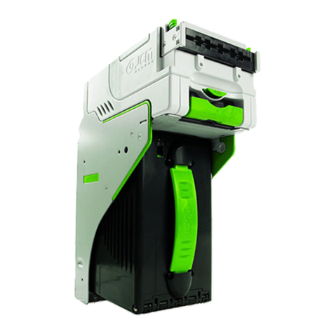
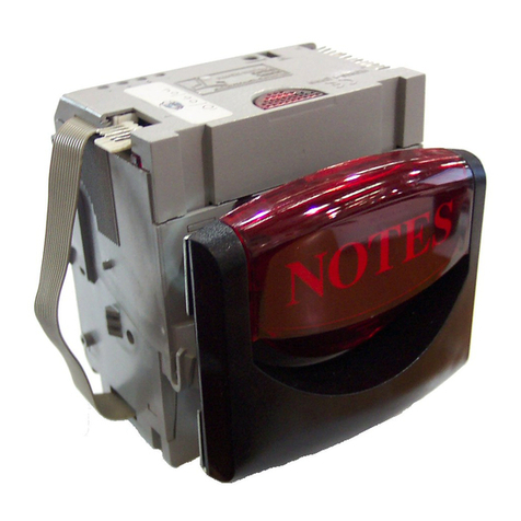
JCM ivision series Quick setup guide

DRAFT 5 © 2010, Japan CashMachine Co, Limited
iVIZION™Series
Next-Generation Banknote Acceptor
Integration Guide
Revision A, May 5, 2010
CONFIDENTIAL PROPERTY OF JCM GLOBAL
DRAFT RELEASE FOR OEM INTEGRATION USE ONLY

This product document (hereinafter referred to as “Guide”) is fully covered by legal Copyrights owned by the Japan Cash
Machine, Co., Ltd., (hereinafter referred to as “JCM”) under Japanese laws and other Foreign Countries.
This Manual contains many copyrighted, patented or properly registered equipment items manufactured by JCM, that
are prohibited and illegal to duplicate, replicate, copy in whole, or in part, without the express authorization by JCM with
the following exceptions:
1. When an authorized JCM agency or distributor duplicates the Manual for sales promotion and/or service
maintenance of the product, or technical service personnel education as required; and
2. When an end user duplicates the Manual to maintain operation of the product or operate the product in general.
JCM retains all rights to amend, alter, change or delete any portion of this Manual in whole, or in part, or add items
thereto without notice regarding the product or its related products.
JCM is a registered trademark of Japan CashMachine Co, Limited. All other product names mentioned herein may be
registered trademarks or trademarks of their respective companies. Furthermore, ™, ®and © are not always mentioned
in each case throughout this publication.
Copyright © 2010 By Japan CashMachine Co, Limited
iVIZION™ Series Next-Generation Banknote Acceptor Integration Guide
CONFIDENTIAL PROPERTY OF JCM GLOBAL
REVISION HISTORY
Rev №.Date Reason for Update Comment
A05-05-10
Initial Document
1
2
Contains Transmitter Module
FCC ID: VZQNRWA3
MODEL NO.: NRWA3
IC: 8285A-NRWA3
This device complies with Part 15 of FCC Rules and RSS-Gen of IC Rules. Operation is subject to the following two conditions:
(1) this device may not cause interference, and (2) this device must accept any interference, including interference that may
cause undesired operation of this device.
FCC WARNING
Changes or modifications not expressly approved by the party responsible for compliance could void the user’s authority to
operate the equipment.
FCC NOTICE
This equipment has been tasted and found to comply with the limits for a Class A digital device, pursuant to part 15 of the FCC
Rules. These limits are designed to provide reasonable protection against harmful interference when the equipment is operated
in a commercial environment.
This equipment generates, uses and can radiate radio frequency energy and, if not installed and used in accordance with the
instructions, may cause harmful interference to radio communications. Operation of this equipment in a residential area is likely
to cause harmful interference in which case the user will be required to correct the interference at his own expence.
IC NOTICE
This class A digital apparatus complies with Canadian ICES-003.
Cet appareil numerique de la classe A est conforme a la norme NMB-003 du Canada.
CONFIDENTIAL PROPERTY OF JCM GLOBAL DRAFT 5© 2010, Japan CashMachine Co, Limited
i
iVIZION™ Series
Integration Guide
Table of Contents Page
TOC
1 GENERAL INFORMATION......................................................................................1
Description.......................................................................................................................... 1
iVIZION Unit........................................................................................................................ 1
Component Names............................................................................................................. 2
2 SPECIFICATIONS....................................................................................................3
Technical Specifications ..................................................................................................... 3
Environmental Specifications .............................................................................................. 3
Electrical Specifications ...................................................................................................... 3
Structural Specifications...................................................................................................... 4
3 INSTALLATION .......................................................................................................4
Installation Procedure ......................................................................................................... 4
Installation Process......................................................................................................................... 4
Cable Interconnection ......................................................................................................... 5
DIP Switch Configurations .................................................................................................. 5
Primary LED Indications ................................................................................................................. 5
Cleaning Procedure ........................................................................................................................ 6
4 VARIOUS IVIZION UNIT DIMENSIONS ..................................................................8
iVIZION Entire Unit Outside Dimensions ............................................................................ 8
iVIZION Installation/Maintenance Space Requirements ................................................................. 9
Various Cash Box Unit Dimensions ............................................................................................. 10
5 TECHNICAL CONTACT INFORMATION ..............................................................11
Americas & Oceania ..................................................................................................................... 11
JCM Global ................................................................................................................................. 11
Europe, Africa, Russia & Middle East ........................................................................................... 11
JCM Europe GmbH .................................................................................................................... 11
UK & Ireland.................................................................................................................................. 11
JCM United Kingdom Ltd............................................................................................................ 11
Asia ............................................................................................................................................... 11
JCM Gold (HK) Ltd. .................................................................................................................... 11
Japan Cash Machine Co, Limited (HQ) ...................................................................................... 11
6 INDEX.....................................................................................................................13

CONFIDENTIAL PROPERTY OF JCM GLOBAL DRAFT 5© 2010, Japan CashMachine Co, Limited
iii
iVIZION™ Series
Integration Guide
List of Figures Page
LOF
Figure 1 iVIZION Unit..................................................................................................1
Figure 2 iVIZION Component Names .........................................................................2
Figure 3 Interface Harness Installation Location.........................................................4
Figure 4 M4 Screws Locations (Left/Right Side).........................................................4
Figure 5 Flat Head Screws Locations (Rear Side)......................................................4
Figure 6 Cable Interconnection ...................................................................................5
Figure 7 iVIZION Sensor Cleaning Locations .............................................................6
Figure 8 iVIZION Banknote Acceptor Unit Outside Dimensions .................................8
Figure 9 iVIZION Installation and Maintenance Space Requirements Diagram .........9
Figure 10 Maximum Gradient Angle = 50 Degrees.......................................................9
Figure 11 iVIZION Standard Cash Box Outside Dimensions......................................10
Figure 12 iVIZION Large Cash Box Outside Dimensions ...........................................10

CONFIDENTIAL PROPERTY OF JCM GLOBAL DRAFT 5© 2010, Japan CashMachine Co, Limited
v
iVIZION™ Series
Integration Guide
List of Tables Page
LOT
Table 1 iVIZION Technical Specification ....................................................................3
Table 2 iVIZION Environmental Specification ................................................................3
Table 3 iVIZION Electrical Specifications.......................................................................3
Table 4 iVIZION Structural Specifications......................................................................4
Table 5 Denomination INHIBIT DIP Switch Settings......................................................5
Table 6 JCM Private Line DIP Switch Setting ................................................................5
Table 7 Software DIP Switch Settings ...........................................................................5
Table 8 Serial Communications DIP Switch Settings.....................................................5
Table 9 LED Error Pattern Indications ...........................................................................5
Table 10 iVIZION Sensor Cleaning Locations ...............................................................7

CONFIDENTIAL PROPERTY OF JCM GLOBAL DRAFT 5© 2010, Japan CashMachine Co, Limited
1
iVIZION™ Series
Next-Generation Banknote Acceptor
Integration Guide
Revision A
Description
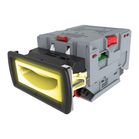
This section provides a general overview of the
iVIZION™ Next-Generation Banknote Acceptor
Series pictured in Figure 1. This first section is
designed to help you navigate through this guide
with ease and provides the following information:
• iVIZION™ Unit
• Component Names
• Primary Features
• Model Description
• Type Description
• Software Description
• Precautions
• Specifications
• Unit Dimensions
• International Compliance
• Technical Contact Information.
In order to make operation of this device easier and
make navigation within this manual simpler, the
following illustrations were used within the text:
• Safety Instructions,which need to be
observed in order to protect the operators and
equipment, have been written in bold text and
have been given the pictographs:
• Special Notes, which effect the use of the
Banknote Acceptor, have been written in italic
text and have been given the pictograph:
• Steps, requiring the operator to perform
specific actions are given sequential numbers
(1., 2., 3., etc).
1 GENERAL INFORMATION
iVIZION Unit
Figure 1 iVIZION Unit

CONFIDENTIAL PROPERTY OF JCM GLOBAL DRAFT 5© 2010, Japan CashMachine Co, Limited
2
iVIZION™ Series Next-Generation Banknote Acceptor Integration Guide
Component Names
Figure 2 illustrates the iVIZION™ Component Names and Locations.
Figure 2 iVIZION Component Names
A.Acceptor Unit
B.Front Upper Guide Access Lever (Acceptor Unit)
C.Bezel (Option)
D.Interface Connector
E.Rear Upper Guide Access Lever (Transport Unit)
F.Transport Unit
G.Frame Housing
H.DIP Switch Block (Denomination INHIBIT)
I. DIP Switch Block (JCM Custom Private Line)
J.Acceptor Unit Release Pushbutton
K.Status LED (Four (4) Colors: Red/Yellow/Green & Blue)
L.Front Panel Bezel JPL Connector
M.Transport Unit Release Lever
N.Power ON LED (Green)
O.USB (Mini-B) Software Download/Calibration
& Maintenance Connector
P.Cash Box
Q.Stack Volume Indicator Window
R.Cash Box Window - confirms the last stacked
Banknote Denomination Value
S.Lock Installation Hole (user provided)
T.Pusher Lever - manually moves the Pusher
Plate down (Activate to confirm the denomination value
through Cash Box Window “R”).
A
B
C
D
E
F
G
H
I
JK
L
MN
O
Q
P
R
S
T

CONFIDENTIAL PROPERTY OF JCM GLOBAL DRAFT 5© 2010, Japan CashMachine Co, Limited
3
iVIZION™ Series Next-Generation Banknote Acceptor Integration Guide
2 SPECIFICATIONS
Technical Specifications
Environmental Specifications
Electrical Specifications
Table 1 iVIZION Technical Specification
Banknote Types Accepted: Long edge: 110-170 mm (4.33-6.69 in.)
Short edge: 60-85 mm (2.36-3.35 in.).
Barcode Coupon*
*. Refer to the specific Country’s “Bar Code Coupon Specification” for more details.
Standard Specification
a) Read Code interleaved: 2 of 5
b) Narrow Bar: 0.5mm-1.0mm (0.19-0.23 in.)
c) Wide Bar: Narrow Bar = 3 : 1
d) Characters: 18 Characters
e) Print Position: Middle (by dividing a Coupon equally on the left, right, top and
bottom of the Coupon’s exact center)
f) Print Width: Wider than 10mm (0.39 in.).
Insertion Direction: Refer to the specific Country’s Software Information Sheet.
Processing Speed:
Approximately 2 seconds from Banknote insertion to Vend signal output.
Approximately 3 seconds from Banknote insertion to completion of the
stacking operation.
Validation Method Optical
Diagnostic Indicators: Power LED, Status LED, Bezel LED (Optional)
Escrow: 1 Note
Cash Box Type†:
†. User supplied installed Locks (including the attached Plate, Lock and Key).
Secure Cash Box
Intelligent Cash Box (available with RF-ID Specification)
Cash Box Capacity‡:
‡. The number of Notes stacked depends on the Banknote’s condition.
Standard: 500 Banknotes
Large: 900 Banknotes.
Fraud Detection: Equipped
Interface:
USB Interface: USB Specification Rev.2.0 Hi Speed Transfer (480 Mbps)
Serial Interface: Photo-Coupler Isolation
Serial Interface: RS232 Communication Protocol.
Table 2 iVIZION Environmental Specification
Operating Temperature: 5º C to ~ +50º C (41º F to ~ 122º F)
Storage Temperature: -20º C to ~ +70º C (-4º F to ~ 158º F)
Relative Operating Humidity: 15% to ~ 85% RH (non-condensed)
Relative Storage Humidity: 15% to ~ 85% RH (non-condensed)
Installation: Indoors Only
Table 3 iVIZION Electrical Specifications
Supply Voltage: 12V DC (-10%) ~ 24V DC (+10%)
Current Consumption:
Standby: 24V DC = 0.2A, 12V DC = 0.2A
Operation: 24V DC = 1.3A, 12V DC = 2.3A
Maximum: 24V DC = 3.2A, 12V DC = 3.0A
Hydrothermal Condition Table
[°C]
[RH%]
Allowable Operating
Temperature and
Humidity Range
40°C/85%
60°C/40%

CONFIDENTIAL PROPERTY OF JCM GLOBAL DRAFT 5© 2010, Japan CashMachine Co, Limited
4
iVIZION™ Series Next-Generation Banknote Acceptor Integration Guide
Structural Specifications
This section provides installation and operating
instructions for the iVIZION™ Series Banknote
Acceptor Unit. The information within contains the
following features:
• Installation Process
• DIP Switch Configurations
• Connector Pin Assignments
• Preventive Maintenance
• Clearing Banknote Jam
• Cleaning
• Interface Schematic
• Operational Flowchart
I
NSTALLATION
P
ROCESS
Mounting holes are provided in each Frame Unit to
attach the iVIZION™ to a related Machine during
installation. Select and perform the following steps
to install the iVIZION™ Unit:
1. Install the Interface Harness to the Frame
Grounding Plate (FG PLT) (See Figure 4 a) using
the two (2) Floating Collars (See Figure 4 b), the
single (1) M2.6x12 W Washer (See Figure 4 c),
the single (1) M2.6x10 W Washer (See Figure 4
d) and the single (1) M2.6 Nylon Nut (See
See Figure 4 e) to the Frame Assembly.
2. When a side mounting configuration is preferred,
bolt the left and right side of the iVIZION™
Frame into its intended location using six (6) M4
Screws on both sides of the Frame (3 Screws on
each side as shown in Figure 4).
3. When an end mounting configuration is preferred,
remove the Cash Box and bolt the rear end of the
iVIZION™ Frame into its intended location using
four (4) UNC6-32 Flat Head Screws from inside
the back end of the Frame as shown in Figure 5.
When installing the iVIZION™ Unit into the Host
Machine, refer to Figure 12 “iVIZION Installation
and Maintenance Space Requirements Diagram”
on page 9 of this document.
Table 4 iVIZION Structural Specifications
Weight Empty: Approximately 4.1kg (9.04 lbs)
Mounting: Horizontal (Maximum gradient limitation within 50 degrees; See Figure
12 on page 10)
Outside Dimensions: Refer to “iVIZION Banknote Acceptor Unit Outside Dimensions” on
page 8 of this document.
3 INSTALLATION
Installation Procedure
a
b
b
c
d
e
Figure 3 Interface Harness Installation Location
Figure 4 M4 Screws Locations (Left/Right Side)
Figure 5
Flat Head Screws Locations (Rear Side)
NOTE: The length of the M4 Screws should
be selected in order not to puncture the
Plastic Surface of the iVIZION™ Frame
when aside mounting configuration is
preferred.

CONFIDENTIAL PROPERTY OF JCM GLOBAL DRAFT 5© 2010, Japan CashMachine Co, Limited
5
iVIZION™ Series Next-Generation Banknote Acceptor Integration Guide
Cable Interconnection
Figure 6 illustrates the Cable Harness interconnect-
ion requirements between the iVIZION™ and a
Host Machine.
DIP Switch Configurations
This portion provides the denomination DIP Switch
Block Settings for the iVIZION™ Unit.
P
RIMARY
LED I
NDICATIONS
The iVIZION™ Unit pair of Color LED indications
appear when various operating and error conditions
occur.
Table 5 Denomination INHIBIT DIP Switch Settings
Validation CPU Board SW1
Switch
No. Switch ON Switch OFF
1VEND 1 INHIBIT VEND 1 ACCEPT
2VEND 2 INHIBIT VEND 2 ACCEPT
3VEND 3 INHIBIT VEND 3 ACCEPT
4VEND 4 INHIBIT VEND 4 ACCEPT
5VEND 5 INHIBIT VEND 5 ACCEPT
6VEND 6 INHIBIT VEND 6 ACCEPT
7VEND 7 INHIBIT VEND 7 ACCEPT
8N/A*
*. Not Applicable (N/A). Never Switched to ON.
OFF (Fixed)
Table 6 JCM Private Line DIP Switch Setting
Validation CPU Board JP1
Switch
No. Non-Marked (O) Marked (C)
1RS-485 Terminating
Resistance Open
RS-485 Terminating
Resistance Closed
a
bc
d
a) iVIZION™ Unit
b) Interface Connector (iVIZION™)
c) Harness
d) Host Machine (Game Machine, Jute Box, Kiosk,
etc.)
Figure 6 Cable Interconnection
SW1
JP1
Table 7 Software DIP Switch Settings
Control CPU Board SW1
Switch
No. Switch ON Switch OFF
1N/A*
*. Not Applicable (N/A). Never Switched to ON.
OFF (Fixed)
2N/A* OFF (Fixed)
3N/A* OFF (Fixed)
4N/A* OFF (Fixed)
Table 8 Serial Communications DIP Switch
Settings
Control CPU Board JP2 & JP3
Switch No. Marked Non-Marked
JP2 Photo-Coupler
Isolation (Standard) RS232
JP3 Photo-Coupler
Isolation (Standard) RS232
Table 9 LED Error Pattern Indications
No. Condition
LED Indications
Power LED*
*. The Power LED lights when Power is supplied to the Unit.
Status LED
1OFF Extinguished
(OUT)
Extinguished
(OUT)
2Initializing Green Lit Blue Flashes
3Stand-by Green Lit Extinguished
(OUT)
4Reject Green Lit Green Flashes
5Banknote Jam Green Lit Yellow Flashes
6Abnormal
Error Green Lit Red Flashes
7Downloading Green Lit Red Lit
Green Lit
8
Performance
Tes t
(Stand-by)
Green Lit Blue Lit
NOTE: When changing the type of iVIZION
Serial Communications, Switches JP2 and
JP3 located on the Control CPU Board must
be set to identical switch positions.
SW1
JP2 JP3

CONFIDENTIAL PROPERTY OF JCM GLOBAL DRAFT 5© 2010, Japan CashMachine Co, Limited
6
iVIZION™ Series Next-Generation Banknote Acceptor Integration Guide
C
LEANING
P
ROCEDURE
To clean the lenses, use a lit-free cloth and a mild
non-abrasive detergent such as liquid dish soap
mixed with water to wipe the dirt from the Lenses.
It is important to keep the Banknote Path, Rollers,
and Belts clean. Use a soft-lint free cloth or a Cot-
ton Swab to wipe dirt and stains from the surfaces
of the Optical Sensors, Rollers and Belts. The Sen-
sor Lenses are transparent, and made of a polymer
material; Handle them with care. Repeat the clean-
ing process as needed until the Transport Path is
free of contaminants.
Sensor Cleaning Procedure:
1. Turn the iVIZION™ Unit Power OFF.
2. Clean the Sensors and lenses in the Acceptor
Unit, the Transport Unit and on the Cash Box
itself. If necessary, remove each Unit and/or open
their Upper Guides for cleaning. See Figure 7 and
Table 10 to locate all cleaning locations.
Figure 7 illustrates and Table 10 lists the iVIZION™
various Sensor and Sensor Lens locations.
Caution: Do not use Alcohol, thinner or
citrus based products for cleaning any
Banknote transport Sensors or surfaces.
NOTE: When closing the Acceptor or
Transport Unit’s Upper Guides, ensure that
they click firmly into place when being
closed. Also, when reassembling the
iVIZION™ Unit, ensure that it re-seats
correctly into place when the reassembly is
complete.
Figure 7 iVIZION Sensor Cleaning Locations
d
g
c
b
h
i
n
e
fo
a
p
jm
l
k
Hidden
Hidden
Hidden

CONFIDENTIAL PROPERTY OF JCM GLOBAL DRAFT 5© 2010, Japan CashMachine Co, Limited
7
iVIZION™ Series Next-Generation Banknote Acceptor Integration Guide
Table 10 iVIZION Sensor Cleaning Locations
Sym. Sensor Cleaning Method
a
Acceptor Unit
Entrance Sensors
Wipe area clean using a lint-free cloth
such as a Micro-Fiber Cloth, or blow clean
using Compressed Air.
bExit Sensors
cUV Sensor (Upper)
dUV Sensor (Lower)
eTransmissive Sensor
fCIS Sensor (Upper)
gCIS Sensor (Lower)
h
Transport Unit
Feed-in Sensors
iFeed-out Sensors
jHome Position Sensor
kHome Position Sensor Lens
lNearly Full Sensor
mCash Box Sensor
n
Cash Box
Home Position Sensor Lens
oCash Box Sensor Lens
pNearly Full Sensor Lens

CONFIDENTIAL PROPERTY OF JCM GLOBAL DRAFT 5© 2010, Japan CashMachine Co, Limited
8
iVIZION™ Series Next-Generation Banknote Acceptor Integration Guide
4 VARIOUS IVIZION UNIT DIMENSIONS
iVIZION Entire Unit Outside Dimensions
Figure 8 illustrates the iVIZION™ Unit’s entire outside dimensions.
Figure 8 iVIZION Banknote Acceptor Unit Outside Dimensions
NOTE: All Dimension are in Millimeters

CONFIDENTIAL PROPERTY OF JCM GLOBAL DRAFT 5© 2010, Japan CashMachine Co, Limited
9
iVIZION™ Series Next-Generation Banknote Acceptor Integration Guide
I
VIZION I
NSTALLATION
/M
AINTENANCE
S
PACE
R
EQUIREMENTS
Figure 9 illustrates the iVIZION™ installation and maintenance and space requirements.
NOTE: All Dimension are in Millimeters
Figure 9 iVIZION Installation and Maintenance Space Requirements Diagram
NOTE: If a maintenance space clearance
area is unavailable, the iVIZION™ Unit will
need to be dismounted when maintenance
procedures need to be performed.
Caution: When installing the iVIZION
Unit into a Host Machine, do not tilt it
downward more than 50 degrees from a
Horizontal position (See Figure 10).
Figure 10 Maximum Gradient Angle = 50 Degrees

CONFIDENTIAL PROPERTY OF JCM GLOBAL DRAFT 5© 2010, Japan CashMachine Co, Limited
10
iVIZION™ Series Next-Generation Banknote Acceptor Integration Guide
V
ARIOUS
C
ASH
B
OX
U
NIT
D
IMENSIONS
NOTE: All Dimension are in Millimeters
Figure 11 iVIZION Standard Cash Box Outside Dimensions
NOTE: All Dimension are in Millimeters
Figure 12 iVIZION Large Cash Box Outside Dimensions

CONFIDENTIAL PROPERTY OF JCM GLOBAL DRAFT 5© 2010, Japan CashMachine Co, Limited
11
iVIZION™ Series Next-Generation Banknote Acceptor Integration Guide
A
MERICAS
& O
CEANIA
JCM Global
Phone: +1-702-651-0000
Fax: +1-702-644-5512
925 Pilot Road, Las Vegas, NV 89119
E-mail: [email protected]
E
UROPE
, A
FRICA
, R
USSIA
& M
IDDLE
E
AST
JCM Europe GmbH
Phone: +49-211-530-645-60
Fax: +49-211-530-645-85
Muendelheimer Weg 60
D-40472 Duesseldorf Germany
E-mail: support@jcm-germany.com
UK & I
RELAND
JCM United Kingdom Ltd.
Phone: +44-(0)870-770-2863
Fax: +44 (0) 190-837-7834
Unit B, Third Avenue
Denbigh West Business Park
Bletchley, Milton Keynes,
Buckinghamshire MK1 1EJ, UK
A
SIA
JCM Gold (HK) Ltd.
Phone: +852-2429-7187
Fax: +852-2929-7003
Unit 1-7, 3/F., Favor Industrial Centre
2-6 Kin Hong Street, Kwai Chung,
N.T. Hong Kong
Japan Cash Machine Co, Limited (HQ)
Phone: +81-6-6703-8400
Fax: +81-6-6707-0348
2-3-15, Nishiwaki, Hirano-ku, Osaka 547-0035
JAPAN
E-mail: Shohi[email protected]
All of these Websites are available via:
http://www.jcmglobal.com
5 TECHNICAL CONTACT INFORMATION
Table of contents
Other JCM Bank Note Validator manuals