CLEANBLAST PORTABLE
CONTENTS
iii
Inspect Before You Connect
Acceptance Criteria
INSPECT
Inspect
IS IT CLEAN
Is it Clean?
CLEAN
Clean
Connect CONNECT
Fiber Optic Connectors
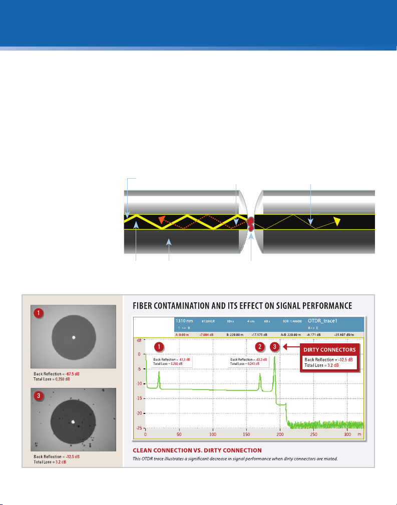
Effect on Signal Performance
Proactive vs. Reactive Inspection
Inspection: Westover FBP Probe
Cleaning: CleanBlast – Portable
Appendix A: Inspection Tips Guide
Appendix B: Cleaning Tips & Adapters Guide
System Status LED's
Solvent Refill
Troubleshooting
Replacing Air Filters
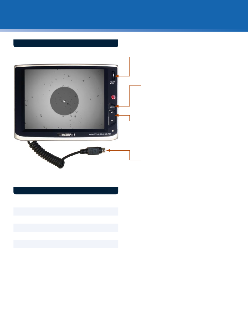
6.4-inch LCD
Optional Configurations
Safety Information
Warranty Information
Ordering Information
Single-mode Connectors.......................................................................15
Multimode Connectors ...........................................................................15
Bulkhead Inspection..................................................................................12
Patch Cord Inspection..............................................................................13
Zones and Acceptance Criteria..........................................................14
Grading Process ............................................................................................14
Bulkhead Cleaning......................................................................................16
Patch Cord Cleaning.........................................................................17
Good Fiber Connection...........................................................................18
Fiber Connections.......................................................................................18
Single Fiber Connectors.............................................................................5
Dirty Connection and Its Effect On Signal Performance ....6
The Problem.......................................................................................................4
The Equipment.................................................................................................4
The Solution .......................................................................................................4
Proactive Inspection.....................................................................................7
Reactive Inspection.......................................................................................7
FBP Probe Overview.....................................................................................8
CleanBlast Overview.....................................................................................9
Inspection Tip Reference Guide ........................................................26
Cleaning Tips Reference Guide..........................................................27
System Status Indicators........................................................................19
Solvent Refill Procedures........................................................................20
Troubleshooting Tips................................................................................22
Replacing Air Filters Procedures .......................................................21
6.4-inch TFT LCD...........................................................................................10
90-degree Handset and Backplane Wand .................................11
Safety Information for Cleaning Solvent.....................................23
General Information ..................................................................................24
CleanBlast – Portable Kit and Units ................................................25
Parts and Solvents.......................................................................................25