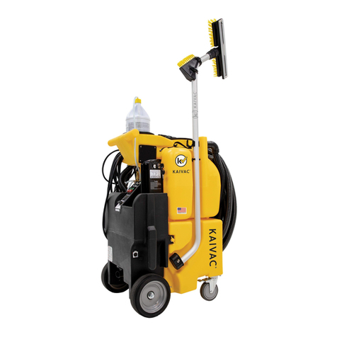
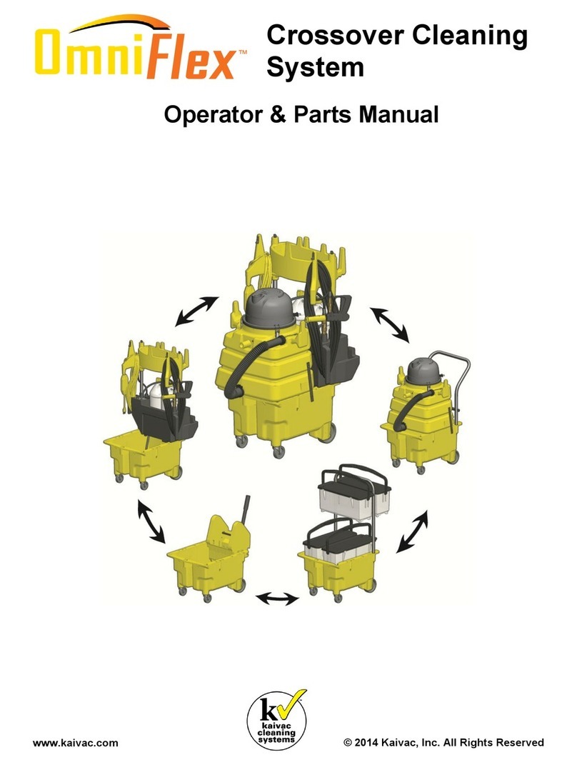
Kaivac NO-TOUCH CLEANING 1200 Series Programming manual

kaivac
cleaning
systems
TM
NO-TOUCH CLEANING®(NTC)
OPERATOR & PARTS MANUAL
©2020 Kaivac, Inc. All rights reserved
www.kaivac.com
P/N: MANUALNTC
kaivac
cleaning
systems
TM


www.kaivac.com
©2020 Kaivac, Inc. All Rights Reserved
kaivac
cleaning
systems
TM
Revision Sheet
Revision sheet foR MAnUALntC
Kaivac, Inc.
2680 Van Hook Ave.
Hamilton, OH 45015
NOTE: Specications and parts are subject to change without notice
Release No. Date Revision Description
1 02/27/20 Initial design/release of MANUALNTC

kaivac
cleaning
systems
TM
4
1-800-287-1136
Customer/Technical Support
opeRAtoR & pARts MAnUAL -
tAbLe ofContents
1.0 Geng Started
1.1 pRodUCt identifiCAtion ........................................................................................................................................... 5
1.2 WARRAnty RegistRAtion........................................................................................................................................... 5
1.3 sAfety pReCAUtions: CoRded Units onLy..................................................................................................................... 6
1.3 sAfety pReCAUtions: CoRded (ContinUed)................................................................................................................... 7
1.3 sAfety pReCAUtions: CoRded (ContinUed)................................................................................................................... 8
1.4 sAfety pReCAUtions: bAtteRy Units onLy .................................................................................................................... 9
1.4 sAfety pReCAUtions: bAtteRy opeRAted (ContinUed) ....................................................................................................10
1.5 bAtteRy infoRMAtion..............................................................................................................................................11
1.6 LiMited WARRAnty pRoteCtion pLAn ..........................................................................................................................12
2.0 Assembly
2.1 tooL ARRAngeMent................................................................................................................................................13
2.2 pRepARAtion foR Use.............................................................................................................................................14
3.0 Maintenance
3.1 bAtteRy Use ........................................................................................................................................................15
3.2 MAChine MAintenAnCe ............................................................................................................................................16
3.3 vACUUM diAgRAM ...................................................................................................................................................17
3.4 pUMp diAgRAM......................................................................................................................................................18
3.5 1200 eLeCtRiCAL diAgRAM .......................................................................................................................................19
3.6 AC eLeCtRiCAL diAgRAM ..........................................................................................................................................20
3.7 QC poWeR pACk eLeCtRiCAL diAgRAM .........................................................................................................................21
4.0 Troubleshoong and Upkeep
4.1 tRoUbLeshooting..................................................................................................................................................22
4.2 tRoUbLeshooting (ContinUed).................................................................................................................................23
4.3 tRoUbLeshooting (ContinUed).................................................................................................................................24
4.4 tRoUbLeshooting tips ...........................................................................................................................................25
4.5 RepLACeMent (MonthLy) .........................................................................................................................................25
5.0 Parts Diagrams and Specicaons
5.1 1200 vAC tAnk AsseMbLy........................................................................................................................................26
5.2 1200 WAteR tAnk AsseMbLy....................................................................................................................................26
5.3 1250 bLACk box AsseMbLy......................................................................................................................................27
5.4 1200 sWitCh pAneL AsseMbLy..................................................................................................................................28
5.5 1200 vALve AsseMbLy.............................................................................................................................................28
5.6 1250 pUMp AsseMbLy ............................................................................................................................................29
5.7 1200 vAC MotoR AsseMbLy .....................................................................................................................................29
5.8 1700/17001 vAC tAnk AsseMbLy.............................................................................................................................30
5.9 1700/17001 WAteR tAnk AsseMbLy .........................................................................................................................30
5.10 1750/17501 pUMp AsseMbLy..................................................................................................................................31
5.11 1700/17001 vAC MotoR AsseMbLy ..........................................................................................................................31
5.12 27001 vAC tAnk AsseMbLy......................................................................................................................................32
5.13 27001 WAteR tAnk AsseMbLy..................................................................................................................................32
5.14 27501 pUMp AsseMbLy...........................................................................................................................................33
5.15 27001 vAC MotoR AsseMbLy ...................................................................................................................................33
5.16 1750/17501/27501 AC bLACk box AsseMbLy ...........................................................................................................34
5.17 QC poWeR pACk AsseMbLy.......................................................................................................................................35
5.18 1700/17001 sWitCh pAneL AsseMbLy .......................................................................................................................36
5.19 27001 sWitCh pAneL AsseMbLy................................................................................................................................36
5.20 1700/17001/27001 vALve AsseMbLy .......................................................................................................................37
5.21 hepA AsseMbLy....................................................................................................................................................37

kaivac
cleaning
systems
TM
5www.kaivac.com
©2020 Kaivac, Inc. All Rights Reserved
1.1 pRodUCt identifiCAtion
1200 seRies (ntC)
AssociAted PAges:
pg. 19
pg. 26-29
pg. 37
pg. 20,21
pg. 30-31
pg. 34-37
AssociAted PAges:
1700 seRies (ntC)
1.0 Geng Started
Idenfy your system below to see the correct manual pages for your product.
pg. 20,21
pg. 32-37
AssociAted PAges:
2700 seRies (ntC)
1.2 WARRAnty RegistRAtion
Thank you for purchasing a Kaivac product. Please take a few moments to register your product at
kaivac.com/warranty.
Why register?
• Ensure your warranty coverage
•
•

kaivac
cleaning
systems
TM
6
1-800-287-1136
Customer/Technical Support
1.3 sAfety pReCAUtions: CoRded Units onLy
1.0 Geng Started
SAVE THESE INSTRUCTIONS
not run appliance over cord. Keep cord away from heated surfaces.
that may reduce air flow.
• Keep all connections dry and off the ground.
• Stay alert - watch what you are doing.
• Keep operating area clear of all persons.
the machine to another function.
• Keep the cord away from heated surfaces.
• Follow the maintenance instructions specified in the manual.
•

kaivac
cleaning
systems
TM
www.kaivac.com
©2020 Kaivac, Inc. All Rights Reserved
1.3 sAfety pReCAUtions: CoRded (ContinUed)
1.0 Geng Started
-
•
GROUND FAULT CIRCUIT INTERRUPTER PROTECTION for spray systems only)
GROUNDING INSTRUCTIONS
-
WARNING
FOR INDOOR USE ONLY
INTENDED FOR COMMERCIAL USE

kaivac
cleaning
systems
TM
8
1-800-287-1136
Customer/Technical Support
plug.
-
1.3 sAfety pReCAUtions: CoRded (ContinUed)
1.0 Geng Started
Figure 1
Table 1
SET
Ampere rating Volts Total length of cord
7.62 m (25 ) 15.24 m (50 ) 30.48 m (100 ) 45.72 m (150 )
More than, A Not more than,
A120 V mm² (AWG)
0 6 — 0.82 (18) 1.3 (16) 1.3 (16) 2.1 (14)
610 —0.82 (18) 1.3 (16) 2.1 (14) 3.3 (12)
10 12 —0.82 (18) 1.3 (16) 2.1 (14) 3.3 (12)

kaivac
cleaning
systems
TM
9www.kaivac.com
©2020 Kaivac, Inc. All Rights Reserved
1.4 sAfety pReCAUtions: bAtteRy Units onLy
accidents.
preventive safety measures reduce the risk of starting the appliance accidentally.
C
• For commercial or residential use.
the risk of fire.
.
inserting plug into electrical outlet.
ashes.
1.0 Geng Started

kaivac
cleaning
systems
TM
1-800-287-1136
Customer/Technical Support
1.4 sAfety pReCAUtions: bAtteRy opeRAted (ContinUed)
may reduce air flow.
•
QUICK RELEASE INSTRUCTIONS
-
unit.
connector locks into place.
GROUNDING INSTRUCTIONS
inserted into an appropriate outlet that is properly installed and grounded in accordance with all local codes and ordinances.
1.0 Geng Started
Battery Specications
Weight With Box, 11 lbs. (4,9 kg)
Body Material Injection Mold Polypropylene
Dimensions (H x W x D) 18 x 7 x 5 in. (45,7 x 17,8 x 12,7 cm)
Voltage 36V DC
Battery Capacity 15 A-hr
Battery Current 15 A DC
Battery Type Lithium-Ion
Approx. Run Time BOL (Beginning of Life) 60 minutes
Approx. Run Time EOL (End of Life) 35 minutes (discontinue use and take to recycling center)
Battery Box Receptacle IP65 / IP67 (not required for UL)
Run Time Hour Meter Acts as “odometer for battery” and runs only when motor switch is ON
Approx. Charge Cycles 400 @ 100% discharge / 500 @ 80% discharge
Cut off Voltage (fully discharged) 30V
Charger Specications
Approx. Charge Time 5.5 hours
Charger Amps 4 Amps
Charge Voltage 42V DC
Charger Voltage 110-240VAC / 36VDC (240VAC version only needs correct plug for wall outlet)
Charging Robustness No special instructions
Battery Charge Memory None
Battery Charge Gauge Yes, LED Indicator
Approx. Charge Cycles 400 @ 100% discharge / 500 @ 80% discharge
Storage/Inventory:
Storage & Operation Ambient Temp 32F (0C) to 80F(27C)
Storage & Shipping Charge 40-60% Charge (35-38VDC)

kaivac
cleaning
systems
TM
www.kaivac.com
©2020 Kaivac, Inc. All Rights Reserved
1.5 bAtteRy infoRMAtion
1.0 Geng Started
-
-
Battery Specications
Weight With Box, 11 lbs. (4,9 kg)
Body Material Injection Mold Polypropylene
Dimensions (H x W x D) 18 x 7 x 5 in. (45,7 x 17,8 x 12,7 cm)
Voltage 36V DC
Battery Capacity 15 A-hr
Battery Current 15 A DC
Battery Type Lithium-Ion
Approx. Run Time BOL (Beginning of Life) 60 minutes
Approx. Run Time EOL (End of Life) 35 minutes (discontinue use and take to recycling center)
Battery Box Receptacle IP65 / IP67 (not required for UL)
Run Time Hour Meter Acts as “odometer for battery” and runs only when motor switch is ON
Approx. Charge Cycles 400 @ 100% discharge / 500 @ 80% discharge
Cut off Voltage (fully discharged) 30V
Charger Specications
Approx. Charge Time 5.5 hours
Charger Amps 4 Amps
Charge Voltage 42V DC
Charger Voltage 110-240VAC / 36VDC (240VAC version only needs correct plug for wall outlet)
Charging Robustness No special instructions
Battery Charge Memory None
Battery Charge Gauge Yes, LED Indicator
Approx. Charge Cycles 400 @ 100% discharge / 500 @ 80% discharge
Storage/Inventory:
Storage & Operation Ambient Temp 32F (0C) to 80F(27C)
Storage & Shipping Charge 40-60% Charge (35-38VDC)

kaivac
cleaning
systems
TM
1-800-287-1136
Customer/Technical Support
1.6 LiMited WARRAnty pRoteCtion pLAn
1.0 Geng Started
in workmanship or materials under normal use and service from the date of purchase.
•
•
•
•
•

kaivac
cleaning
systems
TM
www.kaivac.com
©2020 Kaivac, Inc. All Rights Reserved
2.1 tooL ARRAngeMent
2.0 Assembly
Tool Cup
KaiTutor
KaiTutor
Electric Cord

kaivac
cleaning
systems
TM
1-800-287-1136
Customer/Technical Support
2.2 pRepARAtion foR Use
2.0 Assembly
2. Prepare the cleaning solution you will
be using by attaching the chemical
feed line and cap to the top of your
chemical bottle. Then select the proper
metering tip. (See placard for metering tip
information)
4. If using a cleaning product that foams,
use a foam inhibitor to cut excess. Pour
2 capfuls of inhibitor in the Vac Hose with
Vac running to coat inside of Hose.
5. Check all hoses and spray lines for
damage prior to use. If damage is found,
do not continue until proper repairs are
completed.
6. Plug in machine and test GFCI (Ground
Fault Circuit Interrupter) to ensure it is
working properly. You are now ready.
3. Check machine for all tools and supplies
needed to complete task. See Tool
Arrangement in Section 2.2 of this
manual.
1. Fill machine with clean, cool water.
Reset

kaivac
cleaning
systems
TM
www.kaivac.com
©2020 Kaivac, Inc. All Rights Reserved
3.0 Maintenance
3.1 bAtteRy Use
The bracket mounted on the
black box is where the Power
Pack is mounted.
Lower Power Pack onto
bracket slide, lowering it
down into place.
The Charging Port location
for the Power Pack is pictured
below.
Insert Charger into Charge Port
as displayed below.
To unplug charger, press button
and pull back on Charger cord.

kaivac
cleaning
systems
TM
1-800-287-1136
Customer/Technical Support
3.2 MAChine MAintenAnCe
3.0 Maintenance
CAUTION
ITEM PROCEDURE
Floor
Squeegee
• Check condion of squeegee blades and wheels on the oor tool.
• Rough oor surfaces will cause the blades and wheels to wear out
more quickly. Replace as necessary.
Spray
Gun
• Check spray paern. If spray paern will not pinpoint, clean orice
by removing it with an Allen wrench and ushing. Replace if needed.
• If nozzle becomes dicult to move from high to low pressure,
lubricate nozzle with lithium grease.
Pressure
Hose
• Wipe clean aer each use.
• Check for cuts or frays in the hose jacket, parcularly at the end of
the ngs. Replace hose if cuts are found.
Water
Tank
• Check condion of lter in water tank. Clean as needed.
• Empty the water tank to prevent mildew and bacteria growth. Empty
tank by dipping the vacuum hose into the water tank and transferring
the water to the vacuum tank.
Vacuum Tank • Empty and ush vacuum tank.
• Clean and disinfect.
• Check the oat shuto screen to be sure it is not blocked or dirty. A
plugged lter screen restricts airow and results in reduced sucon.
Leaks • Be alert for leaks around hoses, ngs, spray wand, tanks or
elsewhere.
• Disconnue use unl leaks are repaired.
Electrical System • The ground fault circuit interrupter (GFCI) must be tested before
each use.
• Electrical cord must be inspected for tears or cuts in the insulaon.
Vacuum Wand • Use a wire or coarse brush with acid cleaner to remove residue from
threads on the coupling and coupling nut. Apply grease when done.
HEPA Filter • Replace every 3-6 months depending on use.

kaivac
cleaning
systems
TM
www.kaivac.com
©2020 Kaivac, Inc. All Rights Reserved
3.3 vACUUM diAgRAM
3.0 Maintenance
INTAKE AT
VACUUM
WAND
VACUUM HOSE
FLOAT
SWITCH
VACUUM
TANK
3-STAGE
VACUUM
EXHAUST
BLACK BOX COMPARTMENT
HEPA FILTER

kaivac
cleaning
systems
TM
1-800-287-1136
Customer/Technical Support
3.4 pUMp diAgRAM
3.0 Maintenance
CHEMICAL CAP
CHECK VALVE
CHEMICAL CAP
CHECK VALVE
CHEMICAL
TIP
WATER TANK
CHEMICAL
TIP
CHEMICAL
VALVE
CHEMICAL
INJECTOR W/
CHECK VALVE
DRAW
TUBE
DRAW
TUBE
PULSE
HOSE
SPRAY GUN
UNLOADER
BLACK BOX COMPARTMENT
PUMP
SPRAY
NOZZLE
PRESSURE
HOSE
PRESSURE
HOSE MINI
BALL
VALVE
CHEMICAL
CAP
CHEMICAL
BOTTLE A
CHEMICAL
BOTTLE B
CHEMICAL
CAP

kaivac
cleaning
systems
TM
www.kaivac.com
©2020 Kaivac, Inc. All Rights Reserved
3.5 1200 eLeCtRiCAL diAgRAM
3.0 Maintenance
Black -
Red +
CONTROL PANEL
CONTROL PANEL
PUMP
MOTOR
PUMP
MOTOR
VACUUM
MOTOR
VACUUM
MOTOR
HOUR
METER
HOUR
METER
Bridge

kaivac
cleaning
systems
TM
1-800-287-1136
Customer/Technical Support
3.6 AC eLeCtRiCAL diAgRAMs
3.0 Maintenance
-
+
-
+
-
+
-
+
-
+
-
Black -
Red/White Stripe - White +
6 passes
1 passes
Black -
Red +
Red + Red +
Black - Black -
Red +
Black -
Black -
Red +
CONTROL PANEL
CONTROL PANEL
MOUNTING BRACKET
PUMP
MOTOR
PUMP
MOTOR
VACUUM
MOTOR
VACUUM
MOTOR
HOUR
METER
HOUR
METER
HOUR
METER
HOUR
METER
ARMOR
UNIT
Bridge
Bridge
This manual suits for next models
9
Table of contents
Other Kaivac Cleaning Equipment manuals

Kaivac
Kaivac 2100 Series Product manual

Kaivac
Kaivac 1700 Series Programming manual

Kaivac
Kaivac 2100 Series Programming manual

Kaivac
Kaivac Autovac Programming manual

Kaivac
Kaivac UNIVAC Programming manual

Kaivac
Kaivac 1200 Series Programming manual

Kaivac
Kaivac Autovac Programming manual

Kaivac
Kaivac 1200 Series Programming manual

Kaivac
Kaivac OmniFlex AUTOVAC BATTERY Programming manual