Brunswick Authority22 Reference manual

Page 1 of 5
SERVICE BULLETIN
(C) 2008 Brunswick Bowling & Billiards Corporation, 525 West Laketon Avenue, P.O. Box 329, Muskegon, Michigan 49443-0329
Date: 2/29/08
Bulletin No. SB08-2
Subject: Authority22 Spray Nozzle Assembly
Distribution: Authority22 Customers
Part Numbers
Cleaner Nozzle Body, Long, 14-100410-000
Cleaner Nozzle Body, Short, 14-100411-000
Introduction
It has come to our attention that the cleaner spray nozzle body assembly threads of the bottom ball socket nut are
being broken off inside the cleaner rail of the Authority22. The leading cause of this failure is incorrect adjustment
of the spray nozzle assembly by the user. Refer to Figure 1.
This bulletin will explain the correct adjustment and incorrect adjustment of the spray nozzle body assembly. It will
also provide the procedure for the removal of the threads of the bottom ball socket nut if they have been broken
off inside the cleaner rail assembly.
Figure 1
ASSEMBLY,
CLEANER
NOZZLE BODY
BALL & STEM
BALL SOCKET
JAM NUT
CLEANER RAIL
ASSEMBLY
BOTTOM
BALL SOCKET
NUT
BROKEN
THREADS
OF NUT

Page 2 of 5
Cleaner Spray Nozzle Adjustment Procedure
Tools Required
- 3/4” or 19mm open end wrench
- 7/8" or 22mm open end wrench
- Large towel or several rags
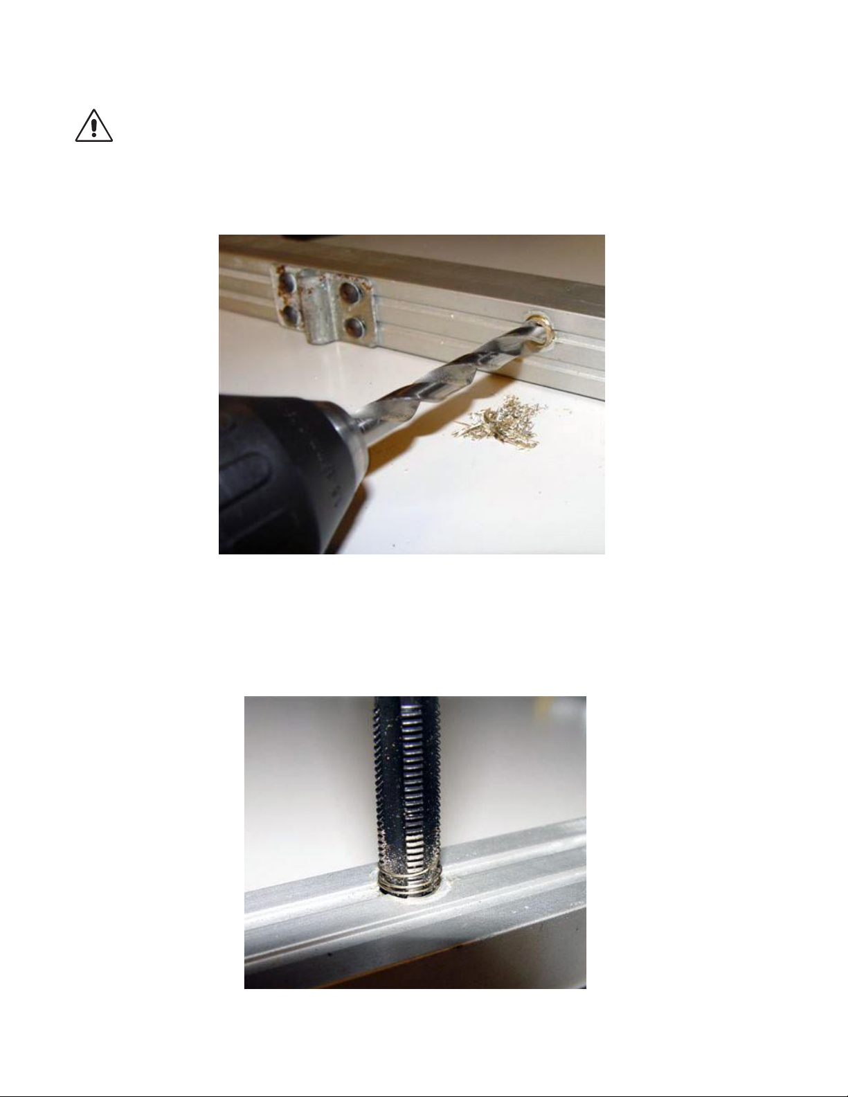
Incorrect Spray Nozzle Adjustment Procedure – Do Not Use!
When performing the adjustment incorrectly, the user will over tighten the ball socket jam nut and hit the stem and
ball with too much force with a hammer or blunt object to adjust the spray nozzle spray to the lane surface. This
will put stress on the bottom jam nut, breaking off the threads of the nut withinthe cleaner rail assembly.
Correct Spray Nozzle Adjustment Procedure
Proper adjustment of the spray nozzle assembly will prevent breakage of the threads of the bottom socket ball nut
inside the cleaner rail assembly. Adjustment will also ensure that the lane cleaner solution gets sprayed onto the
lane surface in the correct area without overspray into the gutters, squeegee and duster cloth.
Place the Authority22 into the operating position and push the lane machine out onto the lane surface at least 12
inches (305mm) out past the foul line. Do not apply power to the Authority22 at this time. Open the covers of the
machine and locate the spray nozzle body to be adjusted.
Step 1
To adjust, hold the bottom ball socket nut of the assembly firmly in place with a 3/4” or 19mm open end wrench.
Do not let the nut turn. If the nut turns and is threaded too far down into the rail, the threads could be broken off.
While holding the bottom nut in place, loosen the jam nut on the ball and stem using a 7/8"or 22mm open end
wrench. Slightly tighten the jam nut by hand and move the stem of the assembly to the desired point at which you
want the fan of the spray to be delivered to the lane surface. Tighten the jam nut with the 7/8" or 22mm open end
wrench. It may take several adjustments to get the correct alignment of the ball and stem and spray nozzle to the
lane surface. Follow Step 2 below to check the cleaner spray pattern to the lane surface.
Step 2
Have a large towel or several rags nearby to soak up cleaner as the cleaner pump is run. Apply power to the
Authority22. Using the Graphical User Interface, (GUI) select “Maintenance,” “Diagnostics,” “Cleaning,” and
“Cleaner Pump.” Press “OK” to run the cleaner pump. The pump will run for 20 seconds, you can stop the pump
prior to the 20 seconds if “OK” is pressed again. Watch where the cleaning solution is applied to the lane surface;
adjust so that there is complete coverage of the lane surface without spraying into the gutter sections of the lane.
Wipe up all excess cleaner from the lane surface and readjust if necessary.

Page 3 of 5
Bottom Ball Socket Nut Thread Removal Procedure
Tools Required
- Hammer
- 1/4” Screw Extractor with Handle
- Cordless Drill and Drill Bits, sizes 1/4” to 11/32"
- 3/8-24 Fine Threaded Tap with Handle
- Cutting Oil
- Vacuum
Step 1
Unplug the power cord to the Authority22 and raise the machine up into the transport position. The nozzle assem-
bly can be extracted or drilled out while the rail is still in the lane machine. The following procedure is shown with
the cleaner rail removed from the machine. Place the end of the extraction tool into the broken threads of the nut
and turn in by hand until tight, then slightly tap the extractor with a hammer to secure it in the broken threads.
Using the extraction tool handle, turn the extractor counter-clockwise until the threads of the nut are removed.
Refer to Figures 2 and 3. Use Caution! If the threads will not come out, do not use excessive force as
you may break the extractor off inside the threads. If the threads cannot be removed with the extractor, the
threads will need to be drilled out. Refer to Step 2.
Figure 2 Figure 3

Page 4 of 5
Step 2
Warning!: Use Safety Glasses.
Using cutting oil and a sharp 1/4” drill bit, drill into the threads. Continue increasing drill bit sizes until the 11/32"
drill bit is used. Use a vacuum to remove all thread material from the hole. Do not use any bits larger than 11/ 32",
as doing so will damage the threads in the cleaner rail assembly. Refer to Figure 4.
Figure 4
Step 3
After drilling, there may be some of the threads of the nut still left inside the rail. To remove the remaining threads,
use a 3/8"-24 fine threaded tap. Insert the tap and slowly turn the tap handle clockwise and counter clockwise
working the tap in until all the threads of the broken nut are removed. Refer to Figure 5.
Figure 5

Page 5 of 5
Step 4
Once the threads are removed, make sure the tap can be easily screwed into the threaded hole of the cleaner rail
assembly. Repeat vacuuming of the threaded hole in the rail to remove all old thread material. Using Teflon tape,
wrap the threads of the bottom ball socket nut of the replacement spray nozzle assembly and screw the threads of
the new assembly in by hand. Refer to Figure 6. Secure the bottom ball socket nut of the replacement spray
nozzle assembly into the rail using a 3/4 or 19mm” wrench. Tighten until there is a 1/4” (6mm) gap between the
bottom of the nut and the cleaner rail.
Figure 6
Step 5
After the nozzle is secure, adjust the spray of the nozzle assembly using the previous spray nozzle adjustment
procedure. Run the Authority22 lane machine and make sure all spray nozzles are spraying. After you have
completed running all the lanes with the machine, remove the cleaner mesh filter screen located under the Graphi-
cal User Interface (GUI) and clean with compressed air. Also take all spray nozzle tips out and clean the check
valve strainers at the end of each spray nozzle. Make sure there are no shavings from drilling or tapping the
cleaner rail, left in the system.
A copy of this Service Letter is available on the Brunswickbowling.com website. If you have questions regarding
this or any other Service Letter, please contact the Brunswick Customer Response Center at 1-800-937-2695 or 1-
Charlie C. Etzel David E. Rice
Customer Response Center Technician Director of Worldwide Service
Other manuals for Authority22
1
Other Brunswick Cleaning Equipment manuals
Popular Cleaning Equipment manuals by other brands

Kärcher
Kärcher NT 22/1 Ap Bp manual

Kärcher
Kärcher SC 2 Deluxe EasyFix operating instructions

Cleanfix
Cleanfix E50x35 Operating instruction

Clarience Technologies
Clarience Technologies Davco Penske Shop Pro ST Technical manual

LOGOPAK
LOGOPAK LogoClean Plastic Contents and Operating instructions

Westfalia
Westfalia 82 86 28 instruction manual