MacDon C Series User manual

C Series
Corn Header
Operator's Manual
262277 Revision A
Translation of Original Instruction
The harvesting specialists.


INTRODUCTION
1
INTRODUCTION
Dear Customer,
The following is some useful information provided to help ensure efficient and safe
operation of this corn head.
This manual gives some information regarding the C-series corn heads.
Read this manual carefully to learn how to operate and service your machine correctly.
Failure to do so could result in personal injury or equipment damage.
This manual should be considered a permanent part of your machine and should remain
with the machine when you sell it.
Since the corn head can be mounted to many models of combines, carefully read your
combine specifications and follow the combine manufacturer’s recommendations for usage,
set-up and operation of the combine.

TABLE OF CONTENTS
2
TABLE OF CONTENTS
1. SAFETY....................................................................................................................................4
1. SAFETY DECALS...................................................................................................................6
1.1 RECOGNIZE SAFETY INFORMATION................................................................................................ 6
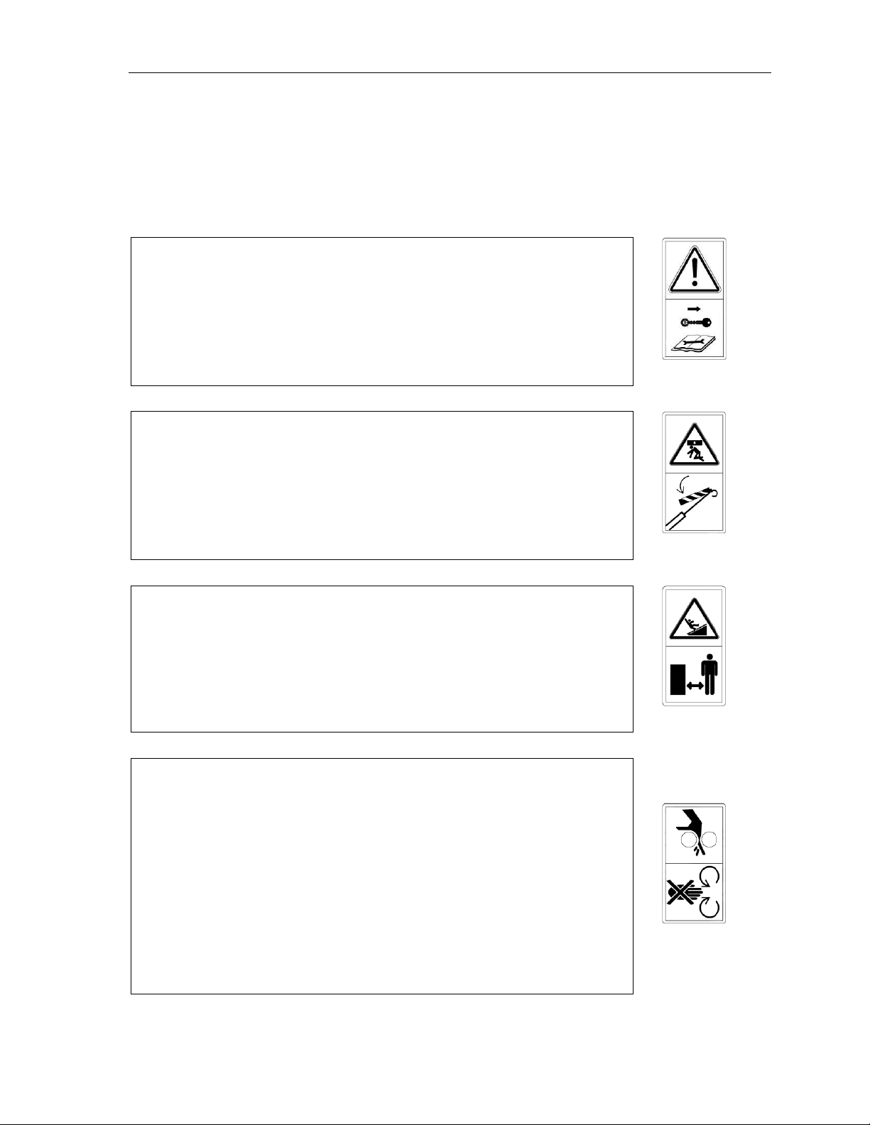
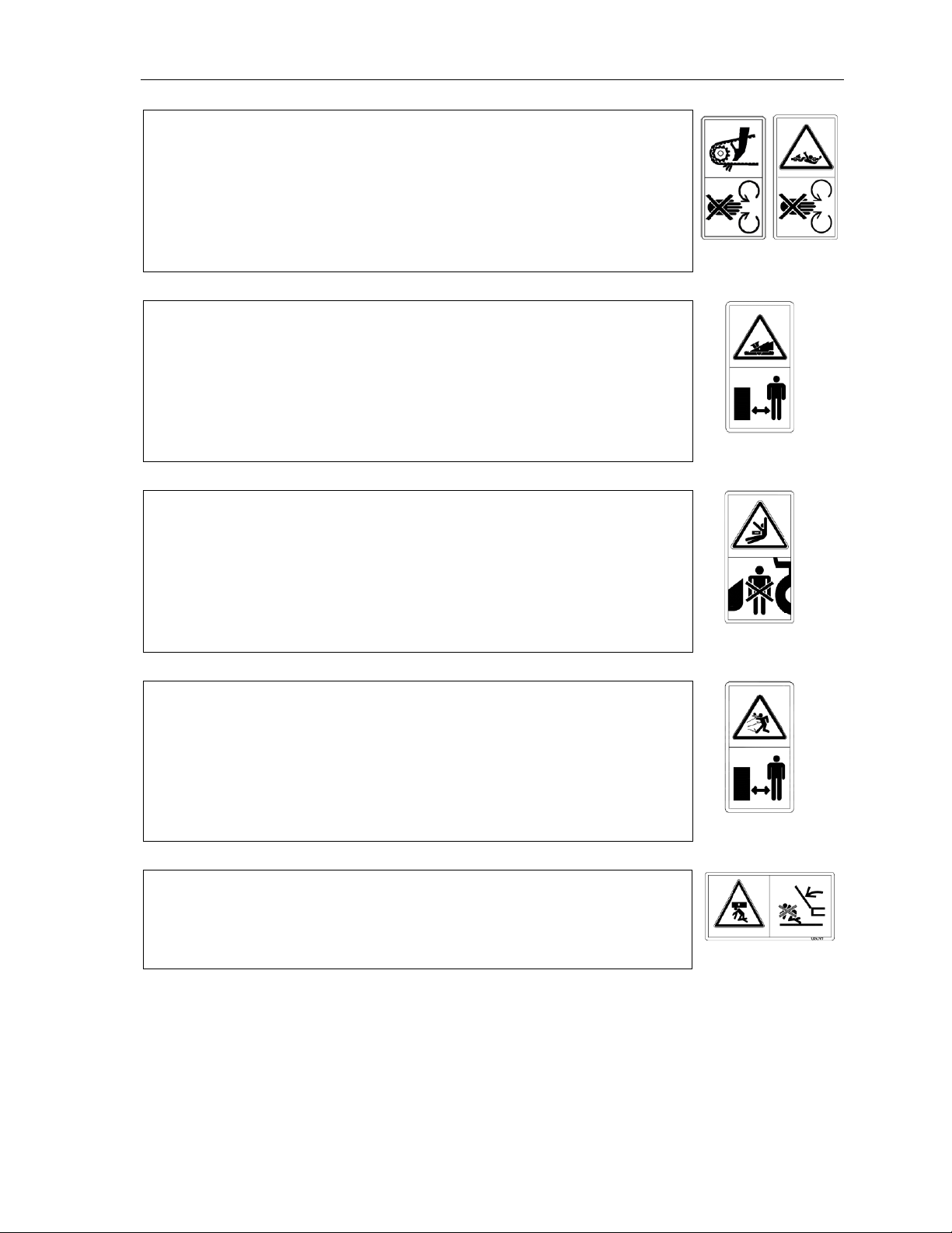
1.2 SAFETY LABEL MEANINGS ............................................................................................................. 7
2. OPERATION AND FUNCTION..........................................................................................14
3. IDENTIFICATION AND SPECIFICATIONS...................................................................17
3.1. IDENTIFICATION ........................................................................................................................... 17
3.2. SPECIFICATIONS ........................................................................................................................... 18
3.2.1. Dimensions................................................................................................................................................. 18
3.2.2. Gearbox Lubricant: EP-00 (liquid) grease, and SAE 80W-140 standard lubricating oil, SAE 85W-140 can
be used as an alternative. ...................................................................................................................................... 18
3.2.3. Pitch of the gathering auger: 560 mm (22”). ............................................................................................. 18
3.2.4. Input shaft speed of the snapping unit drive: 550 rpm................................................................................18
3.2.5. Length of chopped stalk: average 50 mm, depending on crop conditions.................................................. 19
3.2.6. Adjustment of the snapping plate: central in-cab control switch................................................................ 19
3.2.7. Available row spacing: 20” – 22” – 30” – 38” (50.8 cm – 56 cm –76.2 cm –96,5 cm)............................ 19
4. MOUNTING THE CORN HEAD ON THE COMBINE...................................................20
4.1. MOUNTING THE CORN HEAD ON THE COMBINE............................................................................ 20
4.1.1 John Deere 60, 70 and S series .................................................................................................................... 20
4.1.2. CASE IH 1000-2000................................................................................................................................... 21
4.1.3. CIH Flagship & Legacy; NH CR & CX; similarly Challenger MF 9000 Series; Gleaner N, A, R, & S
Series .................................................................................................................................................................... 21
4.1.4. MF 8500 Series........................................................................................................................................... 22
4.1.5. Claas Lexion 500, 600, 700, 7000, & 8000 series; similarly IDEAL 7, 8, & 9 .......................................... 22
4.2. OTHER STEPS FOLLOWING THE SECURING OF THE ADAPTER ON THE COMBINE........................... 23
5. HEADER START-UP PROCEDURE .................................................................................27
6. SETUP PROCEDURE AND ADJUSTMENT OF THE CORN HEAD...........................28
6.1. PARKING STANDS ......................................................................................................................... 28
6.2. AUGER.......................................................................................................................................... 29
6.3. Auger Timing: ............................................................................................................................................... 30
6.4. INPUT GEARBOX DRIVE ............................................................................................................... 32
6.5. SNAPPING UNITS........................................................................................................................... 33
6.5.1. Snapping rolls adjustment........................................................................................................................... 33
6.5.1.1. Distance between snapping roll shafts..................................................................................................... 33
6.5.1.2. Labyrinth .................................................................................................................................................33
6.5.2. Snapping plate adjustment.......................................................................................................................... 34
6.5.3. Vine knife adjustment................................................................................................................................. 36
6.5.4. Gathering chain adjustment ........................................................................................................................ 37
6.6. HEADER DRIVE SHAFTS............................................................................................................... 39
6.7 ADJUSTMENT OF THE CORN HEAD................................................................................................ 39
6.7.1 Header angle adjustment ........................................................................................................................ 39
6.7.2. Plastic snout adjustment ......................................................................................................................... 40

TABLE OF CONTENTS
3
7. HARVESTING.......................................................................................................................41
7.1. STALK CHOPPER........................................................................................................................... 42
8. ROW SPACING ADJUSTMENT ........................................................................................43
9. MOUNTING TO ANOTHER TYPE OF COMBINE........................................................43
10. MAINTENANCE AND LUBRICATION............................................................................44
10.1. FRAME.......................................................................................................................................... 44
10.2. AUGER.......................................................................................................................................... 44
10.2.1. Folding corn head - snapping unit connecting clutches............................................................................ 45
10.2.2. Folding corn head - auger connecting clutches......................................................................................... 45
10.3. INPUT GEARBOXES................................................................................................................. 46
10.4. DRIVE COMPONENTS ............................................................................................................. 47
10.4.1. U-joint shafts:.................................................................................................................................... 47
10.4.2. Chain couplings, Slip clutches........................................................................................................... 47
10.5. SNAPPING UNIT........................................................................................................................ 48
10.5.1. Gearboxes.......................................................................................................................................... 48
10.5.2 Chopper knives.......................................................................................................................................... 50
10.5.3. Snapping roll............................................................................................................................................. 51
10.5.4. Gathering chain......................................................................................................................................... 52
10.5.5. Snapping plate cable................................................................................................................................. 52
11. ELECTRICAL SCHEMATICS ...........................................................................................53
11.1. JD ELECTRICAL SCHEMATIC......................................................................................................... 53
11.2. CNH ELECTRICAL SCHEMATIC..................................................................................................... 54
11.3. AGCO ELECTRICAL SCHEMATIC.................................................................................................. 55
11.4. CLAAS LEXION ELECTRICAL SCHEMATIC................................................................................... 56
11.5. CIH 1000 AND 2000 SERIES ......................................................................................................... 57
12. TROUBLE SHOOTING .......................................................................................................58
12.1. ALARGE QUANTITY OF EARS BUILDS UP BETWEEN THE AUGER AND FEEDER............................. 58
12.2. IN LAID OR LODGED CORN STALKS,THE STALKS DO NOT FEED PROPERLY INTO THE SNAPPING
ROLLS. 58
12.3. ROW UNIT BECOMES PLUGGED WHILE HARVESTING LAID OR LODGED CORNSTALKS................. 58
12.4. STALKS,GRASS OR WEEDS WRAP ON THE SNAPPING ROLL.......................................................... 58
12.5. AUGER DOES NOT ROTATE........................................................................................................... 58
12.6. EARS ARE BROKEN OR SPLIT IN THE AUGER................................................................................. 59
12.8. CHECKS TO RESOLVE FEEDING ISSUES IN DRY CROP........................................................................ 59
13. OFF-SEASON STORAGE OF YOUR CORN HEAD .......................................................60
14. WARRANTY, SERVICE, SPARE PARTS ORDERING..................................................60
15. LUBRICATION CHART......................................................................................................61
15.1 FOR RIGID MODELS....................................................................................................................... 61
15.2 ONLY FOR FOLDING MODELS. ...................................................................................................... 63
16. PRE-HARVESTING INSTRUCTIONS..............................................................................64
17. TORQUE VALUES FOR FASTENERS .............................................................................65

SAFETY
4
1. SAFETY
This is the safety-alert symbol. When you see this symbol on your machine or in this
manual carefully read the message that follows, and be alert to the possibility of personal
injury or death.
Follow recommended precautions and safe operating procedures.
UNDERSTAND SIGNAL WORDS
A signal word –DANGER, WARNING, or CAUTION –is used with the safety-alert
symbol. DANGER identifies the most serious hazards.
DANGER or WARNING safety decals are located near specific hazards. General
precautions are listed on CAUTION safety decals. CAUTION also calls attention to
safety messages in this manual.
FOLLOW SAFETY INSTRUCTIONS
Carefully read all safety messages in this manual and on your machine safety decals.
Keep safety decals in good condition. Replace missing or damaged safety decals. Be
sure new components and repair parts include current safety decals.

SAFETY
5
GENERAL SAFETY GUIDELINES
1. ALLOW ONLY TRAINED AND EXPERIENCED OPERATORS TO OPERATE
THIS MACHINE. Operating this equipment safely requires the full attention of the
operator. Do not wear entertainment headphones while operating this machine.
2. ALWAYS DISENGAGE header drive, shut off the engine and remove key before service,
adjustment, maintenance and lubrication of the corn head.
3. STAY CLEAR of the header when it is in operation.
4. DO NOT OPEN safety shields or covers while the corn head is running.
5. ENGAGE the lock on the feeder lift cylinder before doing any work under or around the
corn head.
6. WORN OR DAMAGED CHOPPER KNIVES must be replaced before operation of the
corn head. Radial clearance between knife and bushing must be properly maintained. See
details in this manual.
7. NEVER remove the warning labels from the machine. If they become damaged or illegible
order replacement parts as shown in the Figures.
8. NEVER remove the safety hydraulic valve of the folding corn heads, located on the back
of the corn head.
9. NEVER close or open the folding corn head when it is in operation.

SAFETY
6
1. SAFETY DECALS
1.1 Recognize safety information
Carefully read Operator’s Manual before operating the machine. When operating, always
observe safety instructions.
WARNING!
This is the safety –alert symbol.
When you see this symbol on your machine or in this manual, be alert to the potential
for personal injury. Carefully read all safety messages in this manual and on your
machine safety signs, and respect them fully to avoid accidents leading to serious
injury or death!
WARNING!
Keep safety signs in good condition. Replace missing or
damaged safety signs. Replacement safety signs are available
from the manufacturer. It is PROHIBITED to remove safety
signs from your machine!
WARNING!
Before installing the machine read the operator’s manual
carefully, learn how to operate, control and keep your machine
in good condition. Do not let anyone operate it without
instruction.
1.326.700
Keep your machine in proper working condition. Unauthorized and non-professional
modifications to the machine may impair the function and safety and affect the
machine life.

SAFETY
7
1.2 Safety label meanings
The function of the labels is to give, easy to understand safety instructions for those
who are staying close to the machine, in order to minimize the risk of accidents. It is
therefore important that these labels always be easy to read, and in complete
condition.
a. Before beginning any maintenance or lubricating, stop the
engine of the combine and remove the key!
1.326.703
b. If you stop the combine while the header is lifted, secure the
loose working cylinder with the help of the device - dive
inhibitor - fixed to the hydraulic working cylinder of the
combine to avoid the accidental crash of the header.
1.326.701
c. Always stay clear of moving elements during operation!
Always disengage header drive, shut off the engine and
remove key before servicing or unclogging header.
1.315.438
d. Always keep your distance from the rotating parts of the
machine. The header’s snapping rolls and other moving parts
can’t be covered completely due to their functions. Do not
feed crop material into machine by hand or attempt to
manually unplug machine while it is running. The stalk rolls
can feed the crop material in faster than you can release your
grip on it. To avoid personal injury or mortal accident always
stop engine before unclogging.
1.326.702

SAFETY
8
e. Never attempt to open or remove shield while the engine is
running. Keep every shield in its place. Avoid direct contact
of your hand, leg, any part of your body or cloth with rotating,
moving machine parts, elements! Before approaching any
moving parts wait for them to completely stop!
1.326.705 1.379.142
f. Avoid bruise!
The loose and non-fixed header can unexpectedly crash
down, so stay away from loose and non-fixed machine!
1.315.439
g. If the engine is still operating, the combine can accidentally
start. Never step between the header and the combine if the
engine is not shut off!
1.379.143
h. Machines equipped with chopper are more dangerous
because of objects thrown out unexpectedly. Do not stay
close to operating machine. Follow the instructions on use
and maintenance of chopper knives!
1.315.440
i. When we are talking about foldable machines there's a
possibility that the wingframes can suddenly fold. Donot stay
under and around the wing frames!
1.326.707

SAFETY
9
j. On some types of corn heads you can find high-pressure
hydraulic system. In case of a pressurized system, the piping
system must not be disturbed or exposed to any external
effects of the damage.
1.332.254
k. The drive shaft rotation.
1.332.252-3
l. To prevent injury from sharp cutting blades: Do NOT operate
without shields in place. Disengage power take-off, stop
engine and remove key before opening covers. Stop engine
and remove key before opening shield. Blades may continue
to rotate after power is shut off. Listen and look for evidence
of rotation before opening shield.
1.372.836
m. To prevent injury from entanglement with rotating auger:
Stand clear of auger while machine is running.
1.372.837
n. Before putting the machine into operation, please remove the
screws which fasten the main frame and side frames on both
sides at delivery.
1.372.916
o. Lifting points on the lifting bar.
514.038.0

SAFETY
10
p. Tie-down point locations.
1.372.890
q. Chopper knife covers are marked with safety decals. Do NOT
operate without covers in place.
1.373.044
r. Operating the machine with feeder lateral tilt feature
enabled may result in damage!
1.379.138
s. QR code label leading to the C-series page.
1.372.822

SAFETY
11
LIST OF ACTIVE MACHINE PARTS
No.
Active machine part
Danger
1.
Snapping units, gathering chains
Snatch, entanglement
2.
Gathering auger
Cutting, entanglement
3.
Outside shields
Nip, bruise
4.
Side chain drive
Snatch, entanglement
5.
Drive shafts
Entanglement
6.
Inner space between combine and corn
head
Crushing
7.
Stalk chopper
Cutting, impact from unexpected flying objects
8.
Shields, snouts
Slipping , stumbling
9.
Lifted machine
Crushing
10.
Hydraulics
High-pressure fluid injection
5
2
8
4
3
10
10
1

SAFETY
12
Illustration below shows placement of safety decals
The figure shows the placement
of machine safety decals.
Attention! The figure shows
only the labels on one side of
the header, but in reality the
decals must be placed
symmetrically on both sides.
Type Numbers:
C3006 C3006C
C3008 C3008C
C3008F C3008CF
C3012 C3012C
C3012F C3012CF
C3016 C3016C
C2208 C2208C
C2212 C2212C
C2218 C2218C
C2012 C2012C
C2018 C2018C
C3808 C3808C
C3812 C3812C

SAFETY
13
Window frame decals:
AGCO
CLAAS/LEXION
JOHN DEERE
CASE IH
CNH
GLEANER RS
AGCO, IDEAL

OPERATION AND FUNCTION
14
7
2. OPERATION AND FUNCTION
The MacDon corn head can be mounted on most combines. Corn ears are detached from the
corn stalks as is shown on the illustration below. The corn stalk enters the area between the
snapping rolls (1,2) which counter-rotate relative to each other, and are pulled downwards
between the snapping plates (3) by the rolls (1,2). This downward directing action causes
the corn ears (5) to impact the snapping plates (3), detaching the ear from the stalk in the
process. The detached ears are moved rearward by the gathering chains (6) into the auger
trough (7) and are conveyed to the combine feeder house by the cross auger (8). Corn stalks
are discharged downward by the snapping rolls (1,2).
If the corn head is equipped with optional stalk chopper, the stalks are chopped into small
fragments by this chopper, located under the snapping rolls.
Attention!
For safe corn head operation, it is essential to respect the instructions on the use of the
corn head when mounted to the combine. Only qualified operators should operate the
machine.
8
6
7

OPERATION AND FUNCTION
15
Operation
The corn head is driven from the combine feeder shaft through a universal drive shaft. Power
is transmitted from the drive shaft by gears encased in an oil bath to a shaft which passes
through the snapping unit.
Torque limiting clutches transmit power from the shaft to each snapping unit.
The auger is chain driven through a torque limiting clutch from the left side snapping unit drive
(or from both sides of large corn heads).
Consider and follow each of the following sequence guidelines before starting operation of
the corn head:
•after a sounding horn start the engine of the combine
•after ensuring that no one is close to the corn head and combine, lower the corn head
into operation position using the combine “lower” function switch
1. Operate the corn head only in the specified harvesting position
2. Engage the combine feeder drive and begin harvesting.
3. Operate at a ground speed that does not exceed that suitable for the combine and corn head
capacity and ground conditions.
4. Perform an emergency stop
During harvesting be aware of unexpected events that may take place requiring immediate
shutdown of the forward movement or combine feeder drive.
Such events could be:
•accident
•foreign materials in the crop (irrigation pipe, gas tube, rocks etc.) which
could enter the corn head
•excessive crop loading (action of torque limiting clutches)
•clogging or blockage
•other breakdown or fault

OPERATION AND FUNCTION
16
The corn head has no specific emergency stop system. The emergency stop is actuated
using the combine systems located in the combine cab. Understand and respect the
relevant instructions of the combine emergency stop procedures as related to the corn
head.
Never leave the combine cab while corn head is in operation.
Non-conforming use:
The corn head is designed only for harvesting in the direction of planting (row
dependent) and for the specified row widths. Harvesting performance can greatly
deteriorate if the corn head is used in other conditions for which it is not intended.
Deterioration in performance can result if:
•The corn head is positioned too high or too low during harvesting
•The corn head is used to harvest crops other than corn or sunflowers when properly
equipped with a sunflower kit.

IDENTIFICATION AND SPECIFICATIONS
17
3. IDENTIFICATION AND SPECIFICATIONS
3.1. Identification
The universal mounting of the corn head permits it to be attached to specific combine types
with the appropriate mounting kit. A mounting kit is assembled to the corn head at the
factory as ordered.
A data plate is located on the left side of the corn head upper beam.
The model number refers to the following: for example:
•C3012 12-row fixed frame with 30” row spacing
•C3012C 12-row fixed frame with 30” row spacing and stalk chopper
•C3012CF 12-row folding frame with 30” row spacing and stalk chopper

IDENTIFICATION AND SPECIFICATIONS
18
3.2. Specifications
3.2.1. Dimensions
3.2.2. Gearbox Lubricant: EP-00 (liquid) grease, and SAE 80W-140 standard lubricating
oil, SAE 85W-140 can be used as an alternative.
3.2.3. Pitch of the gathering auger: 560 mm (22”).
3.2.4. Input shaft speed of the snapping unit drive: 550 rpm
Row Spec
Model
Chopper
Weight
Width
Length
(mm)
Length in
shipping
condition
(mm)
Height
(mm)
Height in
shipping
condition
(mm)
Kg
Lbs
mm
ft.
6R30
C3006
No
2073
4570
4609
15,10
2970
1100
1410
2430
C3006C
Yes
2180
4800
4609
15,10
2970
1100
1410
2430
8R22
C2208
No
2140
4720
4744
15,56
2970
1100
1449
2430
C2208C
Yes
2260
4982
4810
15,78
2970
1100
1449
2430
8R30
C3008
No
2968
6543
6135
20,10
2970
1100
1449
2430
C3008C
Yes
3110
6856
6201
20,34
2970
1100
1449
2430
8R38
C3808
No
2900
6390
7553
24,78
2970
1100
1449
2430
C3808C
Yes
3080
6790
7619
25,00
2970
1100
1449
2430
12R20
C2012
No
2890
6370
6324
20,75
2970
1100
1449
2430
C2012C
Yes
3050
6724
6390
20,96
2970
1100
1449
2430
12R22
C2212
No
3325
7330
6984
22,91
2970
1100
1449
2430
C2212C
Yes
3630
8000
7050
23,13
2970
1100
1449
2430
12R30
C3012
No
3906
8611
9180
30,10
2970
1100
1449
2430
C3012C
Yes
4120
9083
9246
30,33
2970
1100
1449
2430
12R38
C3812
No
4080
8995
11441
37,54
2970
1100
1449
2430
C3812C
Yes
4290
9458
11507
37,75
2970
1100
1449
2430
16R30
C3016
No
5060
11155
12254
40,20
2970
1100
1449
2430
C3016C
Yes
5330
11751
12320
40,42
2970
1100
1449
2430
18R20
C2018
No
4175
9204
9460
31,04
2970
1100
1449
2430
C2018C
Yes
4480
9877
9526
31,25
2970
1100
1449
2430
18R22
C2218
No
4919
10845
10323
33,87
2970
1100
1449
2430
C2218C
Yes
5225
11519
10389
34,08
2970
1100
1449
2430
Row Spec
Model
Chopper
Weight
Transport
width
Width
Length
(mm)
Length in
shipping
condition
(mm)
Height
(mm)
Height in
shipping
condition
(mm)
Kg
Lbs
mm
ft.
mm
ft.
12R30
C3012F
No
4156
9162
4750
15,6
9180
30,1
2970
1100
1584
2430
C3012CF
Yes
4370
9634
4750
15,6
9246
30,33
2970
1100
1584
2430
8R30
C3008F
No
3218
7094
3226
10,6
6135
20,1
2970
1100
1584
2430
C3008CF
Yes
3360
7408
3226
10,6
6201
20,34
2970
1100
1584
2430
Other manuals for C Series
2
This manual suits for next models
26
Table of contents
Other MacDon Farm Equipment manuals

MacDon
MacDon R216 User manual

MacDon
MacDon M155 User manual

MacDon
MacDon 9200 User manual

MacDon
MacDon R113 User manual

MacDon
MacDon M2170 User manual

MacDon
MacDon 973 User manual

MacDon
MacDon M155E4 User manual

MacDon
MacDon D1X Series User manual

MacDon
MacDon PW8 User manual

MacDon
MacDon M150 Owner's manual