Jefferson Professional Tools & Equipment JEFTIGPU200-230 User manual

User Manual
v.1.1
JEFTIGPU200-230
200 AMP
AC/DC TIG WELDER • 230V
HIGH FREQUENCY •PULSE

USER MANUAL
JEFTIGPU200-230
200 AMP HIGH FREQUENCY • PULSE • AC/DC TIG WELDER • 230V
www.jeffersontools.com
2

USER MANUAL
JEFTIGPU200-230
200 AMP HIGH FREQUENCY • PULSE • AC/DC TIG WELDER • 230V
www.jeffersontools.com 3
Introduction 4
Specications 5
Safety Guidelines 6
Operating Guide - Equipment Layout 8
Operating Guide - Control Panel 9
Operating Guide - Adjustment Dial Settings 10
Working Environment 12
Connecting To The Power Supply 12
Welding Current & Arc Voltage 12
Maintenance 12
Troubleshooting 13
Parts Diagram 14
Parts List 15
Environmental Protection 16
WEEE Waste Electrical and Electronic Equipment Statement 16
EC Declaration of Conformity 17
Limited Warranty Statement 18
Important: Please read all these instructions before operating this product and save these instructions. This manual has been compiled by
Jefferson Tools and is an integrated part of the product with which it's enclosed and should be kept with it for the future reference.
This manual describes the purpose for which the product has been designed and contains all the necessary information to ensure its correct and
safe use. We recommend that this manual is read before any operation or, before performing any kind of adjustment to the product and prior to
any maintenance tasks. By following all the general safety instructions contained in this manual you will help to ensure operator safety and extend
the potential lifespan of the equipment.
All photographs and drawings in this manual are supplied by Jefferson Tools to help illustrate the operation of the product. Whilst every effort
has been made to ensure accuracy of information contained in this manual our policy of continuous improvement determines the right to make
modifications without prior warning.
Note: The information contained in this Instruction Manual is designed to assist you in the safe operation and maintenance of the equipment.
Some illustrations in this Instruction Manual may show details or attachments that differ from those on your own equipment. Contact your
nearest Jefferson Dealer if you are unsure about any information included in this manual or require any additional information about the safe use,
operation maintenance, or repair of this equipment.
CONTENTS
USER MANUAL
JEFTIGPU200-230
200 AMP HIGH FREQUENCY • PULSE • AC/DC TIG WELDER • 230V
www.jeffersontools.com
4
• High Frequency, Pulse, 200 Amp AC/DC Tig Welder
• Dual Process: AC inverter TIG/MMA • DC inverter TIG/MMA
• Excellent Performance On Al-Alloy, Carbon Stee, Stainless Steel, Titanium
• Stable Arc and easy ignition
• 230V - 32A Input
• 200A Output
• With Digital Output Display and Finger Touch Digital Controls
• Duty Cycle: 25% @ 200A
• Intelligent protection: Over-voltage, Low-voltage, Over-current, Over-heat
• Supplied in BMC Case
The following welding modes can be congured using the selection options on the digital control panel:
• DC MMA
• DC TIG
• DC Pulse TIG
• AC MMA
• AC TIG
• AC Pulse TIG
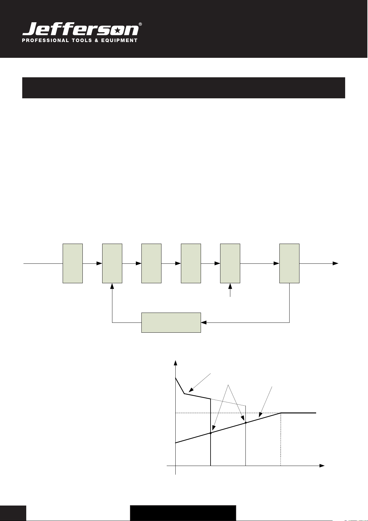
Working Principles:
Rectif
ier
Invert
er
Trans
forme
r
Rectif
ier
Hall
devic
e
Current feedback
control
Single-phase, AC DC AC DC
220V,50Hz
AC Invert
er
AC or DC
Control signal
AC or DC
This equipment has an excellent volt-ampere characteristic. The relation between the conventional rated loading voltage U2 and the conventional
welding current I2 is as follows:
When: I2≤600A , U2=10+0.04I2 (V)
When: I2>600A , U2=34 (V)
INTRODUCTION
67
34
10
0600 I
2
(A)
U
2
(V)
Working
point
Volt-ampere characteristic The relation between the
conventional loading
voltage and welding current
USER MANUAL
JEFTIGPU200-230
200 AMP HIGH FREQUENCY • PULSE • AC/DC TIG WELDER • 230V
www.jeffersontools.com 5
SPECIFICATIONS
JEFTIGPU200-230
Input Voltage 230V ~50Hz
Input Current TIG 35.4A • MMA 39.5A
Input Power TIG 5.2kW • MMA 6.4kW
Power Factor 0.68
Maximum No Load Voltage 66V
Starting Current Adjustment Range TIG MMA
AC DC AC DC
10A-welding current 5A-welding current --- ---
Welding Current Adjustment Range TIG MMA
AC DC AC DC
10A-200A 5A-200A 10A-170A 5A-200A
Downslope Time Adjustment Range 0-10s
Pre Gas Time 0.1-1s
Clearance Effect 15-50%
Efficiency
Duty Cycle (40°C / 10 minutes)
AC DC
25% 200A 25% 200A
60% 90A 60% 110A
100% 70A 100% 80A
Post Gas Time Adjustment R 0.1-10s
Protection Class IP23S
Insulation Class F
Dimensions 470 x 240 x 380mm
Weight 20kg
Please note: Specifications may be subject to change over time.
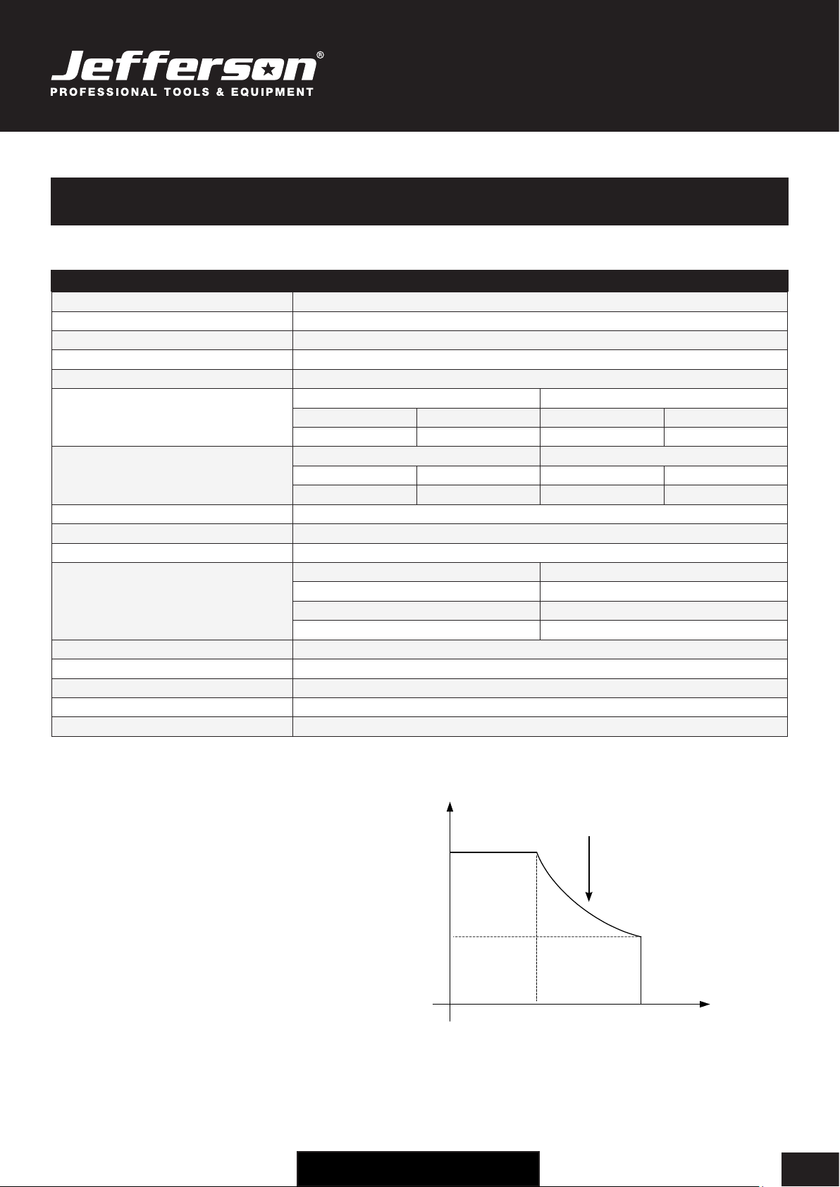
Duty Cycle
The duty cycle is the proportion (percentage) of time
that the welder can work continuously within a 10 min-
ute period at the rated welding current. For example,
60% = 6 minutes constant welding every ten minutes.
Over-heating
In the event of over-heating, the IGBT protection unit
will send an instruction to cut-off the welding current.
An over-heating state will be indicated by the alarm
light on the control panel on the front of the welder.
Allow the welder to cool for 10 minutes and reduce
the welding output current before starting the welding
process again (or else reduce the duty cycle).
I(A)
0
100%
25%
100 200
XThe relation of the welding current and
duty cycle for WSME-200
USER MANUAL
JEFTIGPU200-230
200 AMP HIGH FREQUENCY • PULSE • AC/DC TIG WELDER • 230V
www.jeffersontools.com
6
Please read and ensure that you understand all of the operating instructions, safety precautions and warnings in this Instruction
Manual before operating or maintaining this equipment. Most accidents that result from equipment operation and maintenance
are caused by the failure to observe basic safety rules or precautions. An accident can often be avoided by
recognizing a potentially hazardous situation before it occurs, and by observing appropriate safety procedures. Hazards
that must be avoided to prevent bodily injury or machine damage are identied by warnings on the welder and in this
Instruction Manual. Never use this welder or modify it in any way that has not been specically recommended by the
manufacturer. Contact a qualied electrician for advice on any issues relating to electrical safety in your working environment.
ELECTRICAL SAFETY
Ensure that you check the equipment thoroughly to ensure it is safe and t for purpose before each use. It is important that
you inspect all plugs, sockets, power cables and electrical ttings for wear and damage and repair or replace any defective
components. The risk of electric shock can be minimised by the correct use of the appropriate electrical safety devices.
• We recommend that you t a Residual Current Circuit Breaker (RCCB) in the main distribution board and that a Residual Current Device
(RCD) is used when operating this equipment.
• The Electricity at Work Act 1989 includes legislation that places legal implications on employers to ensure the safety of electrical devices
in the workplace. The regulations dictate that all portable equipment must be inspected regularly and tested to ensure that it is safe for use.
'Portable equipment' means any electrical item that can be moved and this is often referred to as Portable Appliance Testing (PAT). PAT
testing should be carried out regularly on this equipment by trained, authorised personnel, as required by the legislation.
• The Health and Safety at Work Act 1974 states that it is the responsibility of the owner of electrical appliances to ensure that both the
equipment and working environments are maintained to ensure safe operation at all times.
• Check that all equipment cables are secure, correctly insulated, free from damage, and protected against short circuit and overload before
connecting to the power supply. Do not use worn or damaged cables, plugs, sockets or other ttings.
• Ensure that the power supply matches voltage requirements specied on the equipment.
• Ensure the power cable is kept away from heat, oil and sharp edges.
• Do not carry the welder while it is connected to its power source.
• Do not use this equipment in damp / wet conditions.
Welding processes require a high voltage electrical supply which can cause serious injury or death if the correct safety standards and procedures
are not observed.
Ensure that the following general safety guidelines are followed when using this equipment:
• Always wear dry clothing and personal protection equipment and ensure that you are insulated from the workpiece.
• Ensure that the insulation is large enough to cover the full extent of the working area.
• Ensure that the work piece is electrically grounded to an earth source before starting the welding process.
• Never touch any “live” parts or components.
• Always disconnect the equipment from the power source before carrying out any service or adjustments.
• Many components including circuits, nozzles and electrodes can become electrically hot during operation - take care not to touch any parts
until they have cooled sufficiently
• Always ensure that the power cable is long enough to allow you to work at a safe distance from the work piece.
• Ensure that all welding and safety equipment is well-maintained and in full working order before use.
• Never dip the electrode in water for cooling purposes.
• When working above floor level always wear a safety belt to provide fall protection in the event of an electrical shock.
• Ensure that welding work is carried out in a dry environment. Never work with wet equipment or in damp environments.
Note: Some internal electronic components remain positivley charged for up to 90mins after disconnecting from the mains power supply.
SAFETY GUIDELINES

USER MANUAL
JEFTIGPU200-230
200 AMP HIGH FREQUENCY • PULSE • AC/DC TIG WELDER • 230V
www.jeffersontools.com 7
EQUIPMENT SAFETY
General Safety
Operation and maintenance of this equipment can be dangerous and harmful to your health. It is important that you read these instructions
carefully and follow all safety procedures listed. This equipment and any accessories should only be used by fully-trained individuals and any
servicing or maintenance must be carried out by qualied and certied technicians. Please ensure that you check with your nearest Jefferson
stockist for advise if you are unsure about any of the information contained in this manual or contact [email protected]. Do not
modify or adjust this equipment for any other use other than that for which it was designed. Only use Jefferson appoved replacement parts.
Gases & Fumes
Arc welding and cutting processes can produce dangerous fumes and gases. It is important that the following safety precautions are observed:
• Only work in well-ventilated areas
• Keep head and face out of the welding fume
• Use an exhaust at the arc to keep fumes and gases from your breathing area
• Ensure that bystanders, children and animals are kept at safe distance and appropriate ventilation
• Always use an air-supplied respirator when applicable, especially in working environments with poor ventilation to avoid breathing toxic
fumes and gases
The type of fumes and gases released during the welding and cutting process will depend on the welding process and types of metal being used.
Particular care should be taken when using any of the following:
• Antimony • Arsenic • Barium • Beryllium • Cadmium • Chromium • Cobalt • Copper • Lead • Manganese • Mercury • Nickel • Selenium • Silver
• Vanadium
Ensure that you read and fully understand the Material Safety Data Sheet (MSDS) supplied with the welding materials and consumables that you
are using.
Pay particular attention to any safety information relating to safe and dangerous fume and gas volumes.
Use water or down draft welding/cutting tables to capture or reduce toxic fumes and gases.
Be careful when operating in environments containing chlorinated solvent hydrocarbon and cleanser vapours (for example from de-greasing or
spraying operations) to prevent the generation of toxic Phosgene gas.
Never carry out any welding or cutting work in environments where combustible or explosive gases are present.
Arc Ray Protection
Arc welding is a dangerous process and can cause severe damage to eyes and skin. This equipment should only be used by fully trained and
competent individuals.
It is important that you always use the correct Personal Protection Equipment (PPE) and follow the correct procedures at all times.
Always use a suitable safety helmet and visor/glasses to protect against the very bright ultra violet and infra red light. Wear flame resistant welding
gloves and gauntlets to protect your hands and arms from sparks and arc rays.
• Keep welding helmet and safety equipment in good condition. Replace lenses when cracked, chipped or dirty.
• Protect others in the vicinity, use fire proof protective booths, shields and screens where appropriate.
• Do not touch work piece & welding wire at the same time. Use only the cables and rods recommended by the manufacturer.
Fire & Explosion Hazards
Fire and explosions can be caused by hot slag, sparks and the welding arc. Ensure that there are no combustible or flammable materials in the
workplace. Keep all flammable or combustible materials away from the welding area. Any materials that cannot be removed should be covered or
screened.
• Never carry out welding near pets or small children.
• Ensure that a fire extinguisher is available when welding.
• Wear oil free garments without pockets or cuffs.
• Do not weld on combustible or closed containers.
Magnetic Fields
Electrical currents flowing through any conductor causes localised Electrical and Magnetic Fields (EMF). Observe the following safety guidelines:
• Keep people with pacemakers away from the area when the welder is in use.
• Do not wrap the cable around any part of your body while welding.
• Keep all cables as far away from the operator as possible.
USER MANUAL
JEFTIGPU200-230
200 AMP HIGH FREQUENCY • PULSE • AC/DC TIG WELDER • 230V
www.jeffersontools.com
8
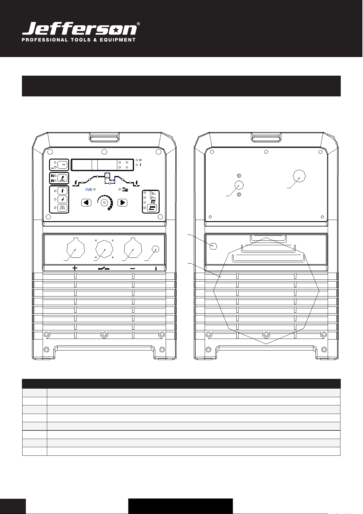
OPERATION GUIDE - EQUIPMENT LAYOUT
DIGITAL CONTROL
AC frequency Balance
AC
~
DC
DC
AC
~
Hz
%
S
V
A
AC/DC PULSED TIG WELDER
1
~
220V
ON
OFF
1234
5
6
7
8
DIGITAL CONTROL
AC frequency Balance
AC
~
DC
DC
AC
~
Hz
%
S
V
A
AC/DC PULSED TIG WELDER
1
~
220V
ON
OFF
1234
5
6
7
8
# Description
1Positive Polarity Output
2Aero Socket (for torch switch control cable)
3Negative Polarity Output
4Gas Input Connections
5Power Switch
6Power Source Input
7Shield Gas Input Connection (connect to argon gas supply)
8Internal Fan
FRONT VIEW REAR VIEW
USER MANUAL
JEFTIGPU200-230
200 AMP HIGH FREQUENCY • PULSE • AC/DC TIG WELDER • 230V
www.jeffersontools.com 9
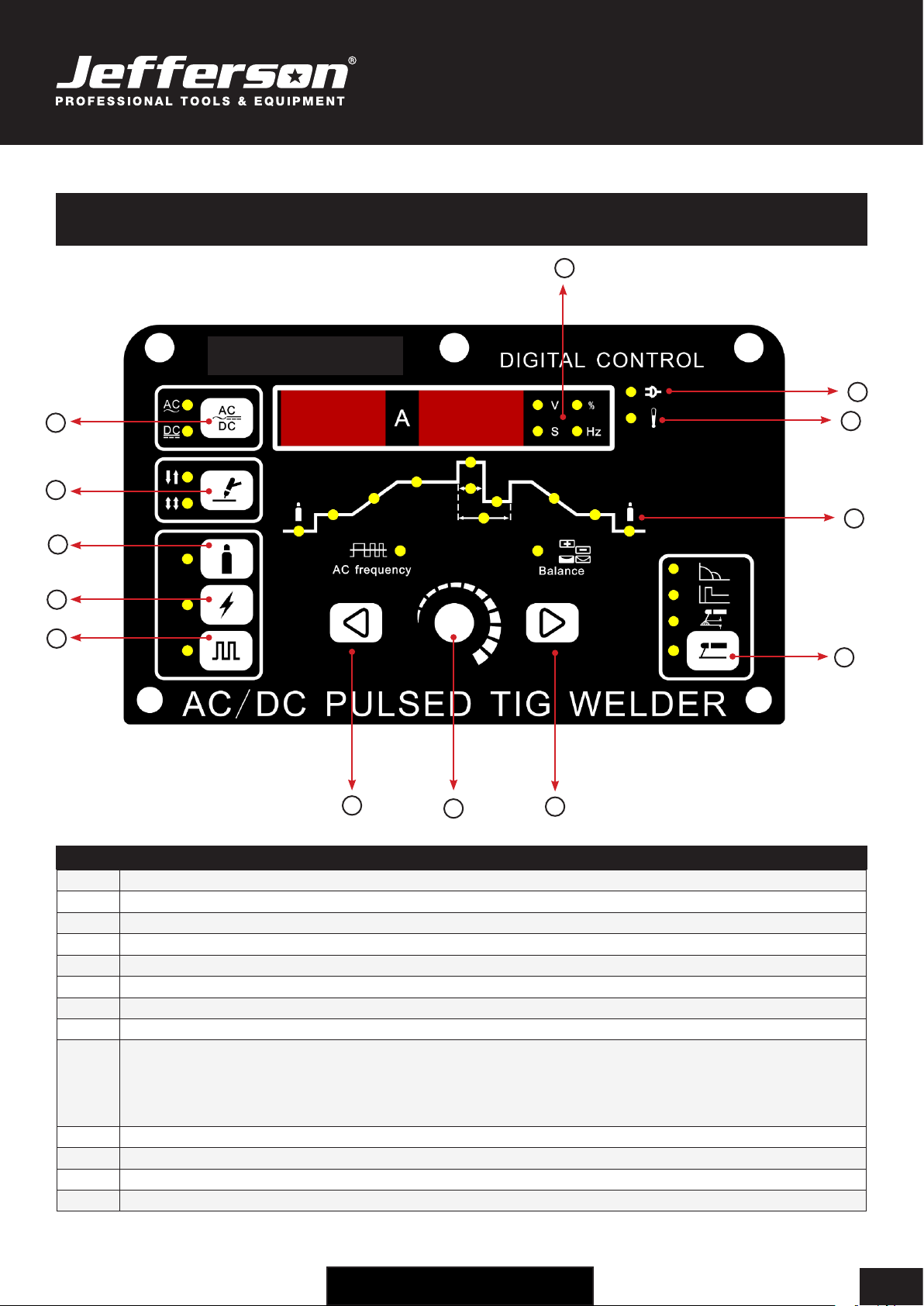
OPERATION GUIDE - CONTROL PANEL
# Description
1AC / DC Selection Button
2Welding Mode Selection (TIG / MMA)
3Gas Test Button
4High Frequency Ignition Button
5Pulse Button
6Parameter Selection (Navigate Left)
7Adjustment Dial (See Adjustment Dial Selection on page 10)
8Parameter Selection (Navigate Right)
9 Rod / Electrode (MMA) Selection:
Arc force 0-10
Hot start 0-10
Arc length 0-10
10 Adjustment Dial Settings Display (See Adjustment Dial Selection on page 10)
11 Alarm Indicator
12 Power Indicator
13 Digital Display
5
4
1
2
3
68
7
9
11
12
10
13
USER MANUAL
JEFTIGPU200-230
200 AMP HIGH FREQUENCY • PULSE • AC/DC TIG WELDER • 230V
www.jeffersontools.com
10
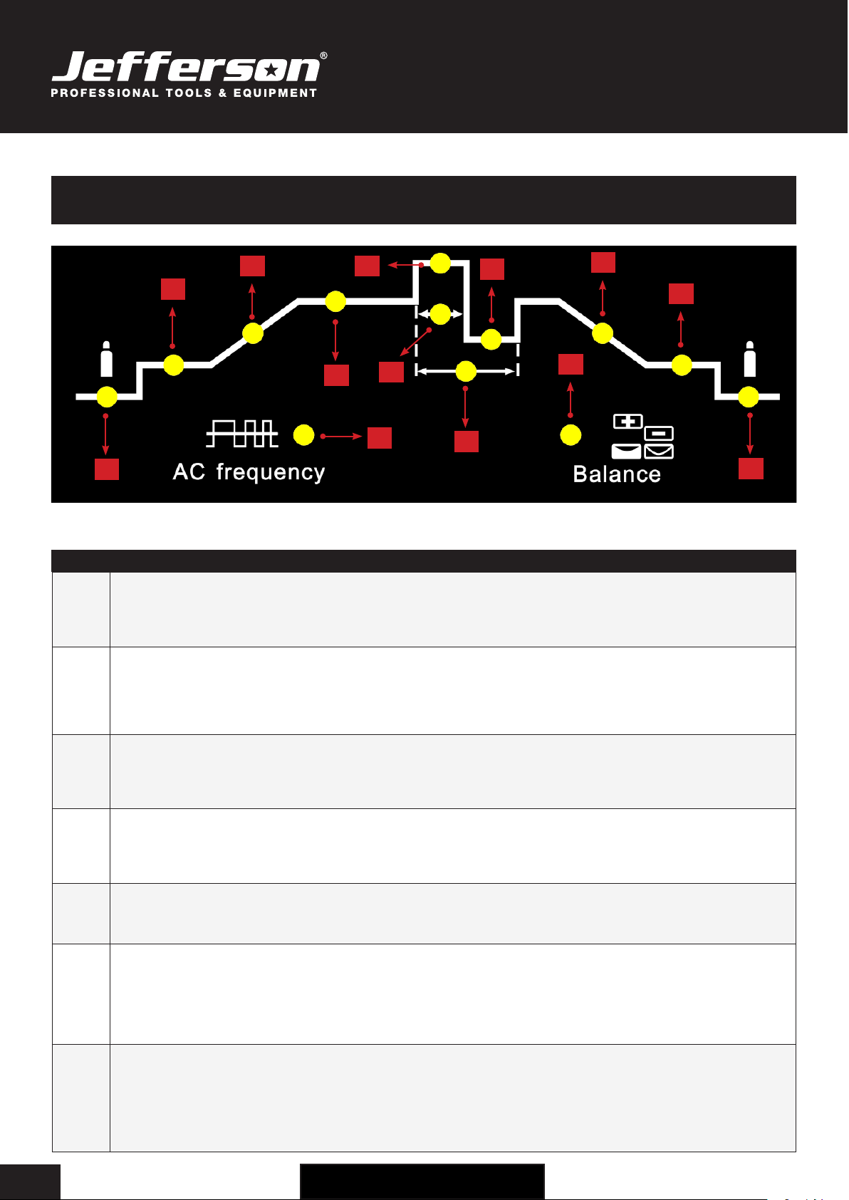
OPERATION GUIDE - AJUSTMENT DIAL SETTINGS
Available parameters where 2T and 4T mode have been selected:
# Description
1 Tpr: Gas pre-ow time
Unit: S
Setting range: 0.1—1
Factory setting: 0.3
2 Is: Starting current (only with 4T)
Unit: A
Setting range: 5—100% of main current Iw (DC) • 10—100%of main current Iw (AC)
Factory setting: 5
3 Tup: Upslope time
Unit: S
Setting range: 0—10
Factory setting: 0
4 Iw: Welding current
Unit: A
Setting Range: 5—200A (TIG-DC) • 10—200A (TIG-AC) • 5—170A (MMA-DC) • 10—170A (MMA-AC)
5 Iw: Welding current
Unit: A
Setting Range: 5—200A (TIG-DC) • 10—200A (TIG-AC) • 5—170A (MMA-DC) • 10—170A (MMA-AC)
6 Dcy: Ratio of pulse duration to base current duration
Unit: %
Setting range: 5—100%
Factory setting: 5%
Important! Only selectable when “Pulse Button” has been pressed.
7 Fp: Pulse frequency
Unit: Hz
Setting range: 0.5—200Hz
Factory setting: 0.5Hz
Important! Only selectable when “Pulse Button” has been pressed.
1
2
3
4
7
6
5810
11
12
9
13

USER MANUAL
JEFTIGPU200-230
200 AMP HIGH FREQUENCY • PULSE • AC/DC TIG WELDER • 230V
www.jeffersontools.com 11
Available parameters where 2T and 4T mode have been selected:
# Description
8 Ib: Base current
Unit: A
Setting Range: 5—200A • (DC) 10—200A (AC)
Important! Only selectable when “Pulse Button” has been pressed.
9 Balance: (only with TIG-AC)
Balance adjustment is mainly used to set the adjustment of eliminating metal-oxide (such as Aluminium, Magnesium and its alloy)
while AC output.
Unit: %
Setting range: 15—50%
Factory setting: 15%
10 Tdown: Downslope time
Unit: S
Setting range: 0—10
Factory setting: 0
11 Ic: Crater arc current (only with 4T)
Setting range: 5—100% of main current Iw (DC) • 10—100% of main current Iw (AC)
Factory setting: 5
12 Tpo: Gas post-ow time
Unit: S
Setting range: 0.1—10S
Factory setting: 3S
13 AC Frequency (only with TIG-AC)
Unit: Hz
Setting range:
50—250 (Iw < 50A)
50—200 (50A ≤ Iw < 100A)
50—150 (100A ≤ Iw <150A )
50—100 (150A ≤Iw <200A)
USER MANUAL
JEFTIGPU200-230
200 AMP HIGH FREQUENCY • PULSE • AC/DC TIG WELDER • 230V
www.jeffersontools.com
12
WORKING ENVIRONMENT
This equipment is designed for use in the following conditions:
• Areas free from moisture and dust with an ambient temperature between 0° to 40°C
• Areas free from oil steam and corrosive gases
• Areas usually not subjected to abnormal vibration or shock
• Areas with suitable ventilation free from any flammable or combustible materials
• Areas not exposed to direct sunlight or rain
Ensure that the equipment is not placed at a distance of 12” (304.79mm) or more from walls or similar obstructions that could restrict the natural
airow or cooling of the system.
CONNECTING TO THE POWER SUPPLY
Warning: Jefferson Tools recommends that this equipment be grounded and connected by a qualified electrician before use.
Connect the earth cable to a suitable ground in compliance with the applicable electrical regulations. Connection to the correct input supply is
necessary to avoid damage to internal components.
Connect the power cable to the required voltage. The primary cable should be connected to the correct supply to avoid arcing or overheating.
Ensure that the input power supply is rated to match the maximum output of this equipment (AC, Single Phase, 50Hz, 230V).
WELDING CURRENT & ARC VOLTAGE
The welding power source is designed with a coiled safety feature that can withstand short-term overload without any adverse effects.
The welding current range values indicated on the control panel and specification plate should be used as a guide only.
The current delivered to the arc is dependent on the welding arc voltage and because the welding arc voltage can vary between different classes
of electrodes, the welding current at any one setting would vary depending on the type of electrode in use.
Use the supplied welding current range values as a guide and then adjust the current setting to suit the welding materials and
processes you are using. If you require any advice, please contact your Jefferson Dealer before attempting to use the equipment.
MAINTENANCE
In order to ensure that this equipment is kept in a safe and efcient working condition please ensure that the following maintenance schedule is
observed. Please note: Failure to keep this equipment in good working order may increase the risk of damage, injury or accident and may void
your standard warranty cover. Contact your nearest Jefferson Dealer for further information about the maintenance and repair of this equipment.
Frequency Procedure
Daily Check that equipment housing, dials, switches and connections are clean and free from dirt, dust,
debris and grease.
Check that all cables, plugs and sockets are in good condition. Do not use this equipment is damage
is detected. Contact your service agent if required and arrange repair before reusing the equipment.
Check for any unusual noises or vibration during startup or operation. Contact your service agent if
detected.
Check that the fan is operational, moving freely and free of dust. If the fan is noisy it may indicate that
there is a build up of dust and dirt within the housing that may result in overheating and malfunction.
Monthly / Regularly
(Depending on use)
Clean the equipment and internal housing using dry compressed air to remove all surfaces of dust and
debris.
Quarterly / Regularly
(Depending on use)
Check that output current matches the current value shown on the control panel. Calibrate as
required. Contact your nearest service agent for advice if required.
Once per Year Measure the insulating impedance at the main circuit, PCB and case. If it below 1MΩ, the insulation is
damaged and in need of repair. Contact your nearest service agent for advice if required.
USER MANUAL
JEFTIGPU200-230
200 AMP HIGH FREQUENCY • PULSE • AC/DC TIG WELDER • 230V
www.jeffersontools.com 13
TROUBLESHOOTING
Welding quality is dependant on the selection of the of the correct consumables for the job at hand, maintenance of the equipment, proper
preparation and the correct welding techniques. The following troubleshooting guide will help you to identify some of the most common problems
you might encounter and the best steps to prevent or overcome them.
Problem Possible Cause Solution
Air pockets or voids in the weld metal
(porosity)
1. The electrodes are damp
2. The welding current is too high
3. Presence of surface impurities such as oil,
grease, paint etc.
1. Only use dry electrodes
2. Reduce the welding current
3. Clean the joint before welding
Gaps & voids left in the root of the weld
root by the electrode
1. Welding current is too low
2. The electrode is too large for the joint
3. Insufcient gap
4. Incorrect sequence
1. Increase the welding current
2. Use a smaller diameter electrode
3. Allow a wider gap
4. Use the correct build-up sequence
Cracks appearing in the weld metal
soon after solidification commences
1. Pressure on the weld joint
2. Insufcient throat thickness
3. Cooling rate is too high
1. Reposition the weld joint with less stress / pressure or try using a
crack resistant electrode
2. Travel slightly slower to allow greater build up in the throat
3. Preheat the plate and cool slowly
Portions of the weld run do not fuse
to the surface of the metal or edge of
the joint
1. The electrode is too small for the welding
process and/or used on plate that is too
heavy or too cold.
2. Welding current is too low
3. Electrode is being used at the wrong angle
4. The travel speed of the
electrode is too fast
5. There is scale or dirt on the joint surface
1. Use larger electrodes and preheat the plate
2. Increase the welding current
3. Adjust the angle so that the welding arc is directed more into the
base metal
4. Reduce the travel speed of the welding electrode
5. Clean the surface before welding
Non-metallic particles are trapped in
the weld metal (slag inclusion)
1. Non metallic particles may be trapped in
any undercut from the previous run
2. Joint preparation was not carried out
correctly or was too restricted
3. Irregular deposits allow slag to be trapped
4. Lack of penetration from the welding arc
because of slag trapped beneath the weld
bead
5. Rust or mill scale is preventing full fusion
6. The wrong electrode for position in which
welding
1. If bad undercut is present clean the slag out and cover with a run
from a smaller diameter electrode
2. Allow for adequate penetration and room by cleaning and
removing any slag.
3. Remove the irregular deposits by chipping or grinding out the
irregular deposits.
4. Use a smaller electrode with sufcient current to give
5. Clean the joint thoroughly before welding
6. Use electrodes best suited for the position in which the welding
process is carried out
Unable to establish a welding arc 1. The primary supply voltage has not been
switched on
2. The welding power source has been
disconnected
3. Loose internal electrical connections
1. Switch on the primary supply voltage
2. Switch on the welding power source
3. Have the equipment and circuitry checked and repaired by a
qualied engineer
Maximum output welding current
cannot be achieved with nominal mains
supply voltage
Defective control circuit Have a qualied service engineer inspect and repair the equipment
Welding current is reduced during the
welding process
Poor work lead connection to the work piece Ensure that the work lead has a positive electrical connection to the
work piece
Power outage / pilot light off / Fan is
not operating
1. Input voltage failure
2. Over voltage
3. Internal electrical fault
1. Re-establish mains supply
2. Check required voltage for the equipment, if necessary move the
equipment to a suitable supply source
3. Have machine tested and
repaired by a qualied technician
The fault indicator light is displayed
and no power is being supplied
1. The equipment has over-heated
2. The equipment is in an over current cut-off
state
3. Internal electrical fault
1. Allow the equipment to cool with the fan-running
2. Switch off the mains supply to the equipment and re-start
3. Have machine tested and repaired by a qualied technician
Contact your nearest Jefferson Dealer if you are unsure about any of the information shown above or require any assistance with maintaining or
troubleshooting your equipment. We recommend that all repairs should be carried out by an approved service agent using Jefferson approved
replacement parts as required. Do not attempt to modify trhe equipment in anyway.
USER MANUAL
JEFTIGPU200-230
200 AMP HIGH FREQUENCY • PULSE • AC/DC TIG WELDER • 230V
www.jeffersontools.com
14
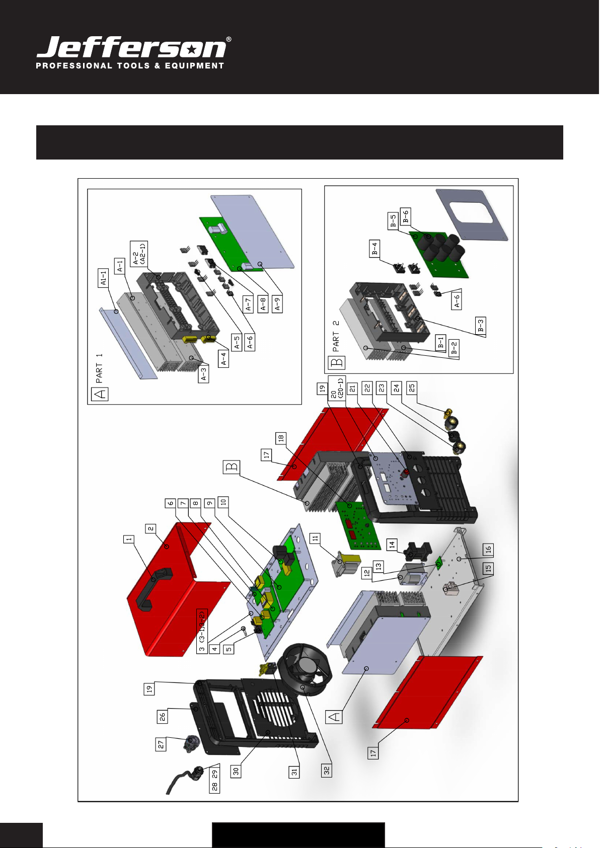
PARTS DIAGRAM
USER MANUAL
JEFTIGPU200-230
200 AMP HIGH FREQUENCY • PULSE • AC/DC TIG WELDER • 230V
www.jeffersontools.com 15
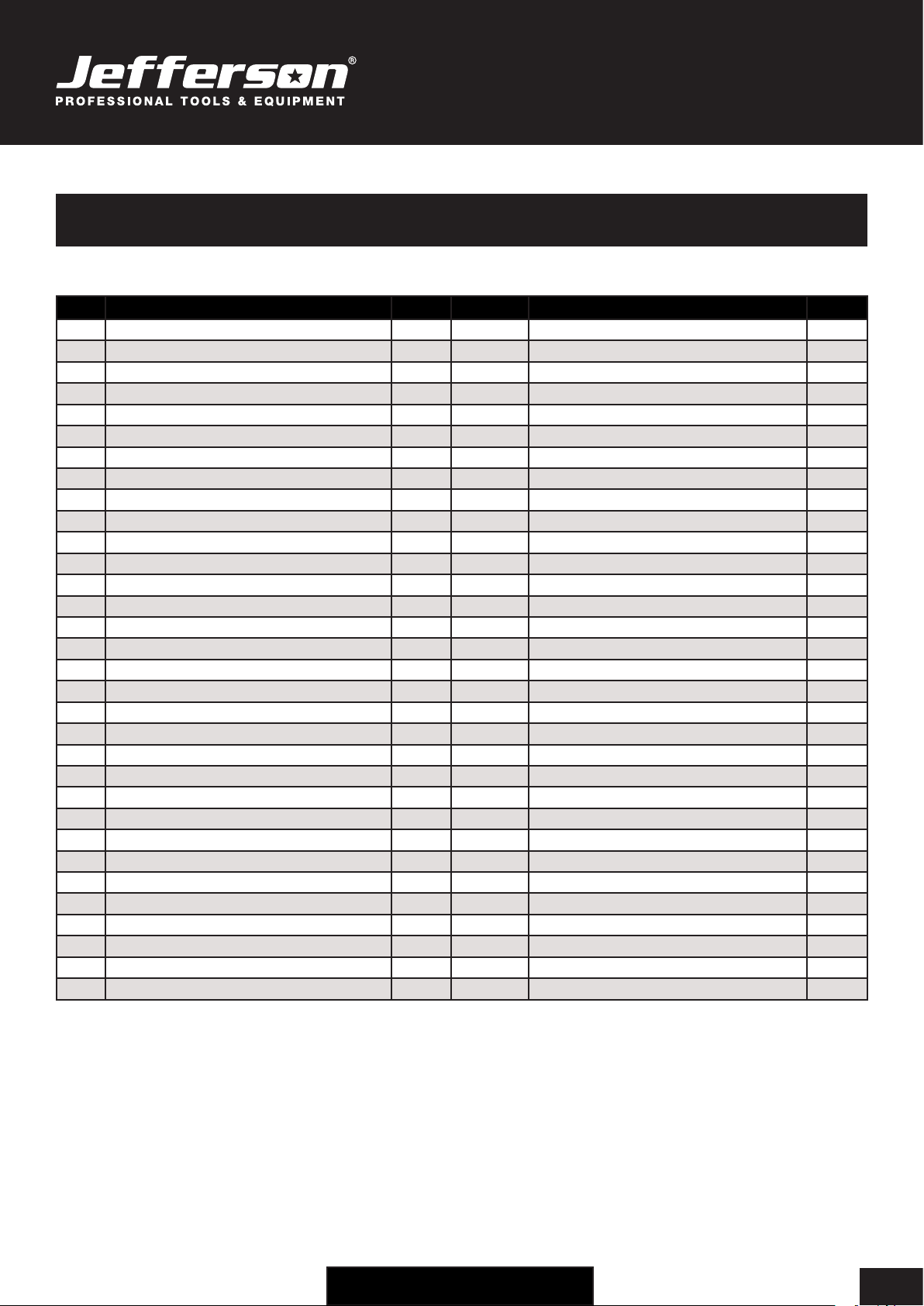
PARTS LIST - MAIN ASSEMBLY
No. Description QTY No. Description QTY
1Handle 1 PART 1
2Cover 1 A--1 Heat Sink i
3Board Installation 1 A--2 Heat Sink Installation
4Fuse 1 A--3 Heat Sink ii
5Fuse Base 1 A--4 Resistance
6TM-2000 (PFC) EMC Board 1 A--5 Thermal Control
7Power Board 1 A--6 IGBT
8315A Output Reciter Installation Board 1 A--7 Fast-Recover Diode
9TP MCU Control Board 1 A--8 IGBT AC Inverter Board
10 HF Arc Board 1 A--9 Cover I
11 Main Transformer 1
12 Inductor 1 PART 2
13 HF Absorb Board 1 B--1 Heat Sink iv
14 HF Coupler 1 B--2 Heat Sink iii
15 Hall 1 B--3 Heat Sink Installation
16 Base 1 B--4 Reciter
17 Side Panel (Left) 2 B--5 IGBT DC Inverter Board
18 TP Display Board 1 B--6 Capacitor
19 Rear Panel 2 B--7 Cover ii
20 Front Panel Cover 1
21 Knob 1
22 Output Panel 1
23 Euro Dinse Socket 2
24 14 Pin Aviation Socket 1
25 Gas Fitting 1
26 Rear Panel Cover 1
27 Switch 1
28 Drop Out Cable Lock 1
29 Power Cable 1
30 Fan Installation 1
31 Solenoid Valve 1
32 Fan 1
USER MANUAL
JEFTIGPU200-230
200 AMP HIGH FREQUENCY • PULSE • AC/DC TIG WELDER • 230V
www.jeffersontools.com
16
WEEE Waste Electrical and Electronic Equipment Statement
Information on Disposal for Users of Waste Electrical & Electronic Equipment
This symbol on the product(s) and / or accompanying documents means that used electrical and electronic products should
not be mixed with general household waste. For proper treatment, recovery and recycling, please take this product(s) to
designated collection points where it will be accepted free of charge.
For private households:
Dispose of this product at the end of its working life and in compliance with the EU Directive on Waste Electrical and Electronic
Equipment (WEEE). Contact your local solid waste authority for recycling information for this equipment.
Disposing of this product correctly will help save valuable resources and prevent any potential negative effects on human health and the
environment, which could otherwise arise from inappropriate waste handling.
Please contact your local authority for further details of your nearest designated collection point.
Penalties may be applicable for incorrect disposal of this waste, in accordance with you national legislation.
For business users in the European Union:
If you wish to discard electrical and electronic equipment, please contact your dealer or supplier for further information.
Information on Disposal in other Countries outside the European Union:
This symbol is only valid in the European Union. If you wish to discard this product please contact your local authorities or dealer and ask for the
correct method of disposal.
ENVIRONMENTAL PROTECTION
Recycle any packaging and unwanted materials instead of disposing of them as waste. All tools, accessories and packaging
should be sorted, taken to a recycling centre and disposed of in a manner which is compatible with the environment.
When the product becomes completely unserviceable, reaches the end of its working life and requires disposal, drain off any
uids (if applicable) into approved containers and dispose of the product and the uids according to local regulations.
USER MANUAL
JEFTIGPU200-230
200 AMP HIGH FREQUENCY • PULSE • AC/DC TIG WELDER • 230V
www.jeffersontools.com 17
EC DECLARATION OF CONFORMITY
We, Tundra Industrial, as the authorised European Community representative of the manufacturer, declare that the
following equipment conforms to the requirements of the following Directives:
Directive: Description:
EN 60974-1:2005 (as amended) Arc welding equipment -- Part 1: Welding power sources
2006/95/EC (as amended) Low Voltage Directive
Equipment Category: AC/DC TIG Welder
Product Name/Model: JEFTIGPU200-230
200 AMP HIGH FREQUENCY • PULSE • AC/DC TIG WELDER • 230V
Signed by: Stephen McIntyre
Position in the company: Operations Director
Date: 13 March 2012
Name and address of manufacturer
or authorised representative:
Jefferson Tools, Herons Way, Chester Business
Park, Chester, United Kingdom, CH4 9QR
Telephone: +44 (0)1244 646 048
Fax: +44 (0)1244 241 191
Email: [email protected]

USER MANUAL
JEFTIGPU200-230
200 AMP HIGH FREQUENCY • PULSE • AC/DC TIG WELDER • 230V
www.jeffersontools.com
18
Jefferson Professional Tools & Equipment, or hereafter "Jefferson" warrants its customers that its products will be free of defects in workmanship
or material. Jefferson shall, upon suitable notication, correct any defects, by repair or replacement, of any parts or components of this product
that are determined by Jefferson to be faulty or defective.
This warranty is void if the equipment has been subjected to improper installation, storage, alteration, abnormal
operations, improper care, service or repair.
Warranty Period
Jefferson will assume both the parts and labour expense of correcting defects during the stated warranty periods below.
All warranty periods start from the date of purchase from an authorised Jefferson dealer. If proof of purchase is unavailable from the end user, then
the date of purchase will be deemed to be 3 months after the initial sale to the distributor.
1 Year
• JEFTIGPU200-230 • 200 AMP HIGH FREQUENCY • PULSE • AC/DC TIG WELDER • 230V
90 Days
• All replacement parts purchased outside of the warranty period
Important: All parts used in the repair or replacement of warranty covered equipment will be subject to a minimum of 90 days cover or the
remaining duration of the warranty period from the original date of purchase.
Warranty Registration / Activation
You can register and activate your warranty by visiting the Jefferson Tools website using the following address:
www.jeffersontools.com/warranty and completing the online form. Online warranty registration is recommended as it eliminates the need to
provide proof of purchase should a warranty claim be necessary.
Warranty Repair
Should Jefferson confirm the existence of any defect covered by this warranty the defect will be corrected by repair or replacement at an
authorized Jefferson dealer or repair centre.
Packaging & Freight Costs
The customer is responsible for the packaging of the equipment and making it ready for collection. Jefferson will arrange collection and
transportation of any equipment returned under warranty. Upon inspection of the equipment, if no defect can be found or the equipment is not
covered under the terms of the Jefferson warranty, the customer will be liable for any labour and return transportation costs incurred.
These costs will be agreed with the customer before the machine is returned.
*Jefferson reserve the right to void any warranty for damages identified as being caused through misuse
Warranty Limitations
Jefferson will not accept responsibility or liability for repairs made by unauthorised technicians or engineers. Jefferson's liability under this
warranty will not exceed the cost of correcting the defect of the Jefferson products.
Jefferson will not be liable for incidental or consequential damages (such as loss of business or hire of substitute equipment etc.) caused by
the defect or the time involved to correct the defect. This written warranty is the only express warranty provided by Jefferson with respect to its
products.
Any warranties of merchantability are limited to the duration of this limited warranty for the equipment involved.
Jefferson is not responsible for cable wear due to flexing and abrasion. The end user is responsible for routine inspection of cables for possible
wear and to correct any issues prior to cable failure.
LIMITED WARRANTY STATEMENT

USER MANUAL
JEFTIGPU200-230
200 AMP HIGH FREQUENCY • PULSE • AC/DC TIG WELDER • 230V
www.jeffersontools.com 19
Claiming Warranty Coverage
The end user must contact Jefferson Professional Tools & Equipment (Tel: +44 (0) 1244 646 048) or their nearest authorised Jefferson dealer where
final determination of the warranty coverage can be ascertained.
Step 1 - Reporting the Defect
Online Method:
• Visit our website www.jeffersontools.com/warranty and complete the Warranty Returns form. You can complete the form online and submit it
to us directly or download the form to print out and return by post.
Telephone Method:
Contact your Jefferson dealer or sales representative with the following information:
• Model number
• Serial number (usually located on the specification plate)
• Date of purchase
A Warranty Returns form will be sent to you for completion and return by post or fax, together with details of your nearest authorised Jefferson
repair centre. On receipt of this form Jefferson will arrange to collect the equipment from you at the earliest convenience.
Step 2 - Returning the Equipment
It is the customer's responsibility to ensure that the equipment is appropriately and securely packaged for collection, together with a copy of
the original proof of purchase. Please note that Jefferson cannot assume any responsibility for any damage incurred to equipment during
transit. Any claims against a third party courier will be dealt with under the terms & conditions of their road haulage association directives.
Please note: Jefferson will be unable to collect or process any warranty requests without a copy of the original proof of purchase.
Step 3 - Assessment and Repair
On receipt, the equipment will be assessed by an authorised Jefferson engineer and it will be determined if the equipment is defective and in need
of repair and any repairs needed are covered by the warranty policy. In order to qualify for warranty cover all equipment presented must have been
used, serviced and maintained as instructed in the user manual.
Where repair is not covered by the warranty a quotation for repair, labour costs and return delivery will be sent to the customer (normally within 7
working days).
Note: If the repair quotation is not accepted Jefferson Professional Tools & Equipment will invoice 1 hour labour time at £30 per hour plus return
carriage costs (plus VAT).
In cases where no fault can be found with the equipment, or, if incorrect operation of the equipment is identified as the cause of the problem, a
minimum of 1 hour labour at £30 per hour plus carriage costs will be required before the equipment will be despatched back to the customer.
Any equipment repaired or replaced under warranty will normally be ready for shipment back to the customer within 7 working days upon receipt
of the equipment at an authorised Jefferson Repair centre (subject to part availability). Where parts are not immediately available Jefferson will
contact you with a revised date for completion of the repair.
General Warranty Enquiries
For any further information relating to Jefferson warranty cover please call +44 (0) 1244 646 048 or send your enquiry via email to warranty@
jeffersontools.com
Disclaimer:
The information in this document is to the best of our knowledge true and accurate, but all recommendations or suggestions are made without
guarantee. Since the conditions of use are beyond their control, Jefferson Tools® disclaim any liability for loss or damage suffered from the use of
this data or suggestions. Furthermore, no liability is accepted if use of any product in accordance with this data or suggestions infringes any patent.
Jefferson Tools® reserve the right to change product specifications and warranty statements without further notification. All images are for
illustration purposes only.
USER MANUAL
JEFTIGPU200-230
200 AMP HIGH FREQUENCY • PULSE • AC/DC TIG WELDER • 230V
www.jeffersontools.com
20
Jefferson Tools,
Herons Way,
Chester Business Park,
Chester,
United Kingdom,
CH4 9QR
Tel. +44 (0)1244 646 048
Email: [email protected]
IMPORTANT! SAFETY FIRST!
Before attempting to use this product please read
all the safety precautions and operating instructions
outlined in this manual to reduce the risk of fire,
electric shock or personal injury.
www.jeffersontools.com
www.jeffersontools.com
Table of contents
Popular Welding System manuals by other brands


Hobart Welding Products
Hobart Welding Products AirForce 375 owner's manual

GF
GF MSA 330 instruction manual

Hakko Electronics
Hakko Electronics FX-888D instruction manual

Abicor Binzel
Abicor Binzel ABIPLAS WELD 100 W operating instructions

EWM
EWM Taurus 355 Basic TDM operating instructions

Thermal Dynamics
Thermal Dynamics PakMaster 100 XL plus operating manual


