Jegs 81374 User manual

Installation Instructions for 81374
Sheet Metal Shears
18 Gauge Capacity
Save This Manual Keep this manual for the safety warnings and precautions, assembly, operating,
inspection, maintenance and cleaning procedures. Write the product’s serial number in the back of the
manual near the assembly diagram (or month and year of purchase if product has no number). Keep this
manual and the receipt in a safe and dry place for future reference.
Read this material before using this product.
Failure to do so can result in serious injury.
SAVE THIS MANUAL.
1-800-345-4545 jegs.com

Table of Contents
Safety ......................................................... 2
Specifications ............................................. 8
Setup .......................................................... 8
Operation .................................................... 9
Maintenance .............................................. 11
Parts List and Diagram .............................. 14
Warranty .................................................... 16
This is the safety alert symbol. It is used to alert you to potential personal injury
hazards. Obey all safety messages that follow this symbol to avoid possible
injury or death.
Indicates a hazardous situation which, if not avoided, will result in death or
serious injury.
Indicates a hazardous situation which, if not avoided,
could result in death or serious injury.
Indicates a hazardous situation which, if not avoided, could result in minor or
moderate injury.
Addresses practices not related to personal injury.
IMPORTANT SAFETY INFORMATION
General Power Tool Safety Warnings
Read all safety warnings and all instructions.
Failure to follow the warnings and instructions may result in electric shock, fire and/or serious injury.
Save all warnings and instructions for future reference.
The term ″power tool″ in the warnings refers to your mains-operated (corded) power tool.
Work Area Safety
1. Keep work area clean and well lit.
2. Do not operate power tools in explosive atmospheres,
such as in the presence of flammable liquids, gases or
dust. Power tools create sparks which may ignite the dust
or fumes.
3. Keep children and bystanders away while operating a power tool.
Cluttered or dark areas invite accidents.
Distractions can cause you to lose control.
1-800-345-4545 jegs.com

Electrical Safety
1. Power tool plugs must match the outlet. Never modify the plug in any way. Do not use any adapter plugs
with grounded power tools. Unmodified plugs and matching outlets will reduce risk of electric shock.
2. Avoid body contact with grounded surfaces such as pipes, radiators, ranges and refrigerators. There is an
increased risk of electric shock if your body is grounded.
3. Do not expose power tools to rain or wet conditions. Water entering a power tool will increase the risk of electric
shock.
4. Do not abuse the cord. Never use the cord for carrying, pulling or unplugging the power tool. Keep cord
away from heat, oil, sharp edges or moving parts. Damaged or entangled cords increase the risk of electric shock.
5. When operating a power tool outdoors, use an extension cord suitable for outdoor use. Use of a cord suitable
for outdoor use reduces the risk of electric shock.
6. If operating a power tool in a damp location is unavoidable, use a Ground Fault Circuit Interrupter (GFCI)
protected supply. Use of a GFCI reduces the risk of electric shock.
Personal Safety
1. Stay alert, watch what you are doing and use common sense when operating a power tool. Do not use a
power tool while you are tired or under the influence of drugs, alcohol or medication. A moment of inattention
while operating power tools may result in serious personal injury.
2. Use personal protective equipment. Always wear eye protection. Protective equipment such as dust mask, non-
skid safety shoes, hard hat, or hearing protection used for appropriate conditions will reduce personal injuries.
3. Prevent unintentional starting. Ensure the Switch is in the off-position before connecting to power source,
picking up or carrying the tool. Carrying power tools with your finger on the Trigger or energizing power tools that
have the Trigger on invites accidents.
4. Remove any adjusting key or wrench before turning the power tool on. A wrench or a key left attached to a
rotating part of the power tool may result in personal injury.
5. Do not overreach. Keep proper footing and balance at all times. This enables better control of the power tool in
unexpected situations.
6. Dress properly. Do not wear loose clothing or jewelry. Keep your hair, clothing and gloves away from
moving parts. Loose clothes, jewelry or long hair can be caught in moving parts.
7. If devices are provided for the connection of dust extraction and collection facilities, ensure these are
connected and properly used. Use of dust collection can reduce dust-related hazards.
8. Only use safety equipment that has been approved by an appropriate standards agency. Unapproved safety
equipment may not provide adequate protection. Eye protection must be ANSI-approved and breathing protection
must be NIOSH-approved for the specific hazards in the work area.
Power Tool Use and Care
1. Do not force the power tool. Use the correct power tool for your application. The correct power tool will do the
job better and safer at the rate for which it was designed.
2. Do not use the power tool if the Switch does not turn it on and off. Any power tool that cannot be controlled with
the Trigger is dangerous and must be repaired.
3. Disconnect the plug from the power source before making any adjustments, changing accessories, or
storing power tools. Such preventive safety measures reduce the risk of starting the power tool accidentally.
3
1-800-345-4545 jegs.com

4. Store idle power tools out of the reach of children and do not allow persons unfamiliar with the power tool or
these instructions to operate the power tool. Power tools are dangerous in the hands of untrained users.
5. Maintain power tools. Check for misalignment or binding of moving parts, breakage of parts and any other
condition that may affect the power tool’s operation. If damaged, have the power tool repaired before use.
Many accidents are caused by poorly maintained power tools.
6. Keep cutting tools sharp and clean. Properly maintained cutting tools with sharp cutting edges are less likely to
bind and are easier to control.
7. Use the power tool, accessories and tool bits etc. in accordance with these instructions, taking into account
the working conditions and the work to be performed. Use of the power tool for operations different from those
intended could result in a hazardous situation.
Service
Have your power tool serviced by a qualified repair person using only identical replacement parts.
This will ensure that the safety of the power tool is maintained.
Shears Safety Warnings
1. Hold power tool by insulated gripping surfaces, when performing an operation where the cutting accessory
may contact hidden wiring or its own cord. Cutting accessory contacting a ″live″ wire may make exposed metal
parts of the power tool ″live″ and could give the operator an electric shock.
2. Let blades cool before touching, changing or adjusting them. Blades heat up dramatically while in use, and can burn
you.
3. If the blades jam, turn the Switch off immediately.
4. Maintain labels and nameplates on the tool. These carry important safety information. If unreadable or missing,
contact JEGS.
5. Avoid unintentional starting. Prepare to begin work before turning on the tool.
6. Do not lay the tool down until it has come to a complete stop. Moving parts can grab the surface and pull the tool out
of your control.
7. When using a handheld power tool, maintain a firm grip on the tool with both hands to resist starting torque.
8. Do not leave the tool unattended when it is plugged into an electrical outlet. Turn off the tool, and unplug it from its
electrical outlet before leaving.
9. This product is not a toy. Keep it out of reach of children.
10. People with pacemakers should consult their physician(s) before use. Electromagnetic fields in close proximity to
heart pacemaker could cause pacemaker interference or pacemaker failure. In addition, people with pacemakers
should: • Avoid operating alone.
• Do not use with Trigger locked on.
• Properly maintain and inspect to avoid electrical shock.
• Properly ground power cord. Ground Fault Circuit Interrupter (GFCI) should also be implemented –it prevents
sustained electrical shock.
11. The warnings, precautions, and instructions discussed in this instruction manual cannot cover all possible
conditions and situations that may occur. It must be understood by the operator that common sense and caution are
factors which cannot be built into this product, but must be supplied by the operator.
4
1-800-345-4545 jegs.com

Vibration Safety
This tool vibrates during use. Repeated or long-term exposure to vibration may cause temporary or permanent physical
injury, particularly to the hands, arms and shoulders.
To reduce the risk of vibration-related injury:
1. Anyone using vibrating tools regularly or for an extended period should first be examined by a doctor and
then have regular medical check-ups to ensure medical problems are not being caused or worsened from use.
Pregnant women or people who have impaired blood circulation to the hand, past hand injuries, nervous
system disorders, diabetes, or Raynaud’s Disease should not use this tool. If you feel any symptoms related to
vibration (such as tingling, numbness, and white or blue fingers), seek medical advice as soon as possible.
2. Do not smoke during use. Nicotine reduces the blood supply to the hands and fingers, increasing the risk of
vibration-related injury.
3. Wear suitable gloves to reduce the vibration effects on the user.
4. Use tools with the lowest vibration when there is a choice.
5. Include vibration-free periods each day of work.
6. Grip tool as lightly as possible (while still keeping safe control of it). Let the tool do the work.
7. To reduce vibration, maintain the tool as explained in this manual. If any abnormal vibration occurs, stop use
immediately.
SAVE THESE INSTRUCTIONS.
5
1-800-345-4545 jegs.com
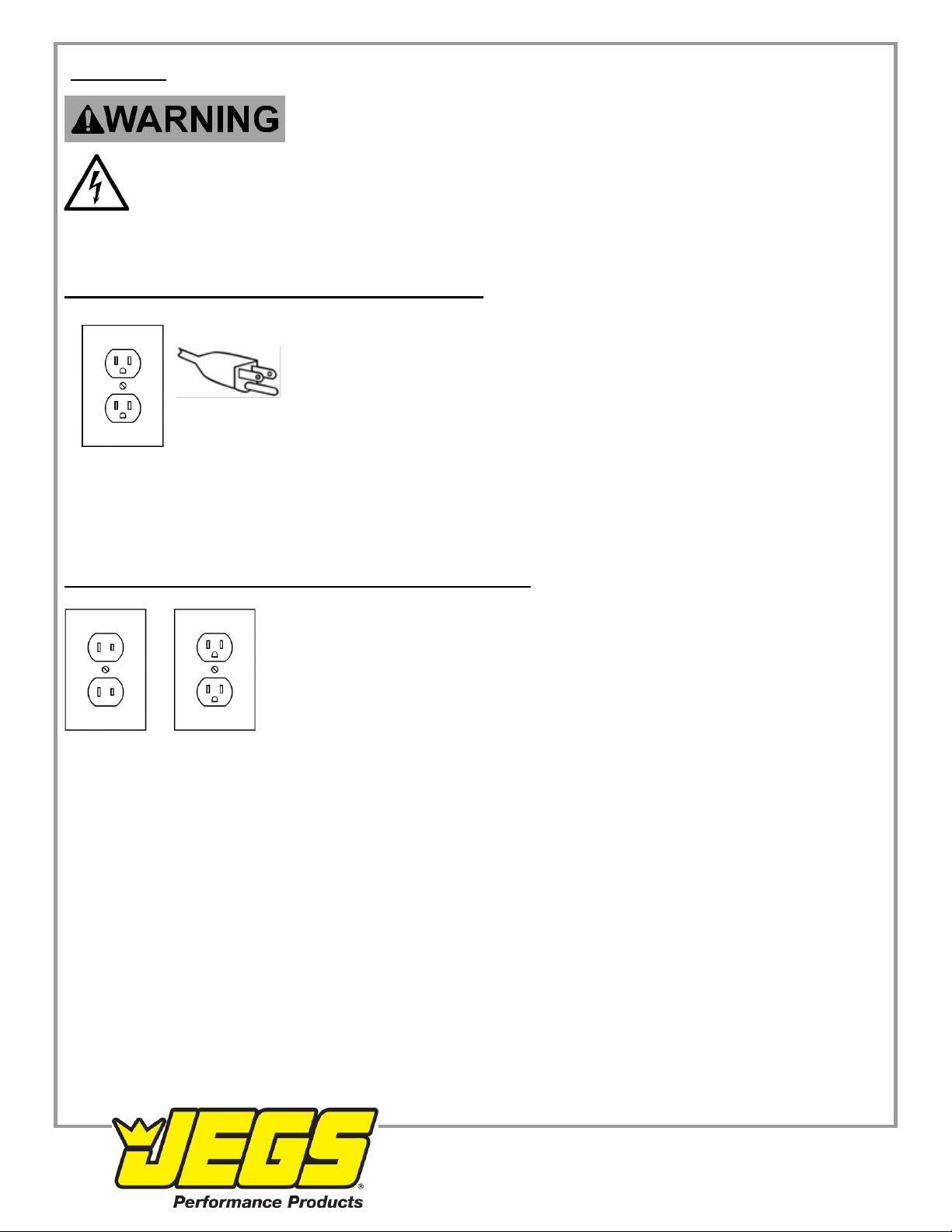
Grounding
TO PREVENT ELECTRIC SHOCK AND DEATH FROM
INCORRECT GROUNDING WIRE CONNECTION:
Check with a qualified electrician if you are in doubt as to whether the outlet is properly grounded.
Do not modify the power cord plug provided with the tool. Never remove the grounding prong from
the plug. Do not use the tool if the power cord or plug is damaged. If damaged, have it repaired by a service
facility before use. If the plug will not fit the outlet, have a proper outlet installed by a qualified electrician.
Grounded Tools: Tools with Three Prong Plugs
3-Prong Plug and Outlet
1. Tools marked with “Grounding Required” have a three wire cord and three prong
grounding plug. The plug must be connected to a properly grounded outlet. If the tool
should electrically malfunction or break down, grounding provides a low resistance
path to carry electricity away from the user, reducing the risk of electric shock. (See 3-
Prong Plug and Outlet.)
2. The grounding prong in the plug is connected through the green wire inside the cord to the
grounding system in the tool. The green wire in the cord must be the only wire connected to the tool’s
grounding system and must never be attached to an electrically “live” terminal. (See 3-Prong Plug and Outlet.)
3. The tool must be plugged into an appropriate outlet, properly installed and grounded in accordance with all codes
and ordinances. The plug and outlet should look like those in the preceding illustration. (See 3-Prong Plug and
Outlet.)
Double Insulated Tools: Tools with Two Prong Plugs
Outlets for 2-Prong Plug
1. Tools marked “Double Insulated” do not require grounding. They have a special double
insulation system which satisfies OSHA requirements and complies with the applicable
standards of Underwriters Laboratories, Inc., the Canadian Standard Association, and the
National Electrical Code.
2. Double insulated tools may be used in either of the 120 volt outlets shown in the
preceding illustration. (See Outlets for 2-Prong Plug.)
6
1-800-345-4545 jegs.com
Extension Cords
1. Grounded tools require a three wire extension cord. Double Insulated tools can use either a two or three wire
extension cord.
2. As the distance from the supply outlet increases, you must use a heavier gauge extension cord. Using extension
cords with inadequately sized wire causes a serious drop in voltage, resulting in loss of power and possible tool
damage. (See Table A.)
3. The smaller the gauge of the wire, the greater the capacity of the cord. For example, a 14 gauge cord can carry a
higher current than a 16 gauge cord. (See Table A.)
4. When using more than one extension cord to make up the total length, make sure each cord contains at least the
minimum wire size required. (See Table A.)
5. If you are using one extension cord for more than one tool, add the nameplate amperes and use the sum to
determine the required minimum cord size. (See Table A.)
6. If you are using an extension cord outdoors, make sure it is marked with the suffix “W-A” (“W” in Canada) to indicate
it is acceptable for outdoor use.
7. Make sure the extension cord is properly wired and in good electrical condition. Always replace a damaged
extension cord or have it repaired by a qualified electrician before using it.
8. Protect the extension cords from sharp objects, excessive heat, and damp or wet areas.
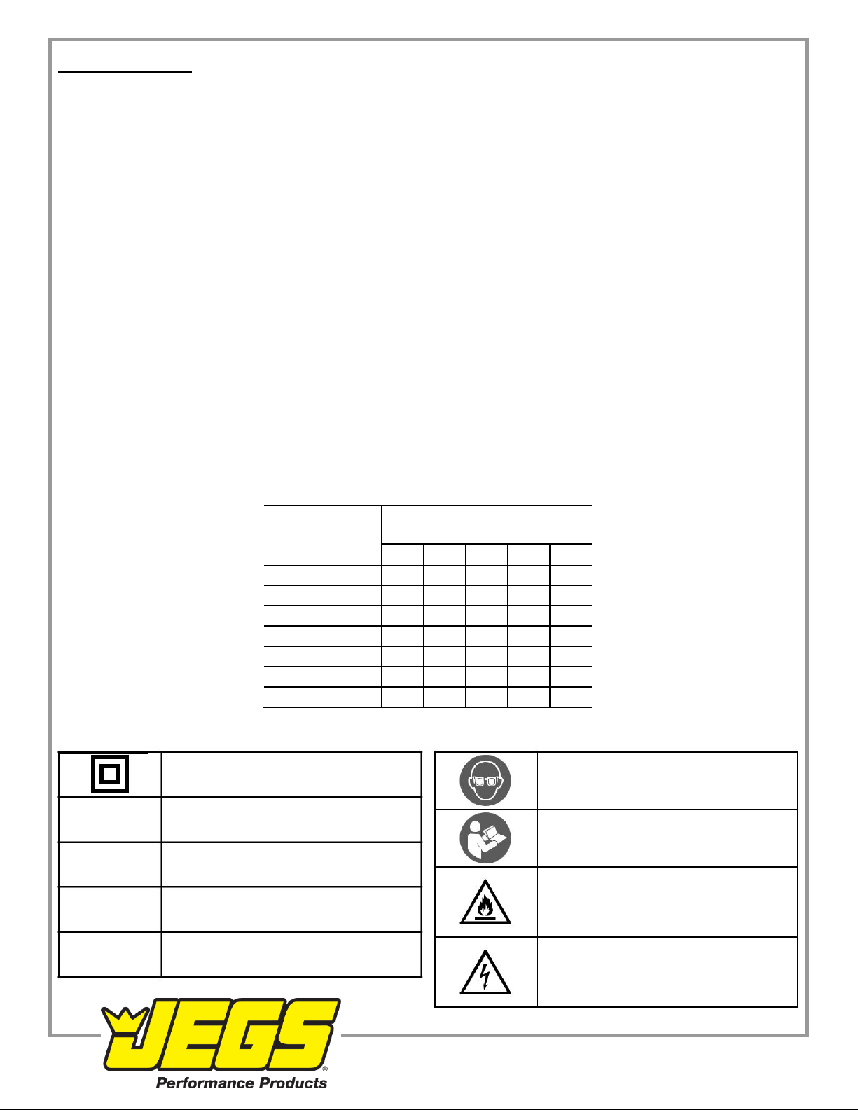
TABLE A
RECOMMENDED MINIMUM WIRE GAUGE FOR EXTENSION CORDS* (120/240 VOLT)
NAMEPLATE
EXTENSION CORD
AMPERES
LENGTH
(at full load)
25´
50´
75´
100´
150´
0 –2.0
18
18
18
18
16
2.1
–3.4
18
18
18
16
14
3.5
–5.0
18
18
16
14
12
5.1
–7.0
18
16
14
12
12
7.1 –12.0
18
14
12
10
-
12.1
–16.0
14
12
10
-
-
16.1
–20.0
12
10
-
-
-
* Based on limiting the line voltage drop to five volts at 150% of the rated amperes.
Symbology
Double Insulated WARNING marking concerning Risk
of Eye Injury. Wear ANSI-approved
safety goggles with side shields
VVolts
Read the manual before set-up
and/or use
~Alternating Current
WARNING marking concerning Risk of
A Amperes Fire. Do not cover ventilation ducts.
Keep flammable objects away.
n0xxxx/min. No Load Revolutions/Minute (RPM) WARNING marking concerning
Risk of electrical shock
Properly connect power cord to
appropriate outlet.
7
1-800-345-4545 jegs.com

Specifications
Electrical Rating
120VAC / 60Hz / 3.5A
Strokes per Minute
3550 SPM
Cutting Capacity
Metal, Aluminum, and Plastic up to 18 gauge
Setup- Before Use:
Read the ENTIRE IMPORTANT SAFETY INFORMATION section at the beginning of this
manual including all text under subheadings therein before set up or use of this product.
Note: For additional information regarding the parts listed in the
following pages, refer to Parts List and Diagram on page 14.
Functions
Power Switch
Oil Port
Power Cord
Guide
Upper
Blade
Lower Blade
Figure A
8
1-800-345-4545 jegs.com

Operating Instructions
Read the ENTIRE IMPORTANT SAFETY INFORMATION section at the beginning of this manual
including all text under subheadings therein before set up or use of this product.
Tool Set Up
TO PREVENT SERIOUS INJURY FROM ACCIDENTAL OPERATION:
Make sure that the Switch is in the off-position and unplug the tool from its electrical
outlet before performing any procedure in this section.
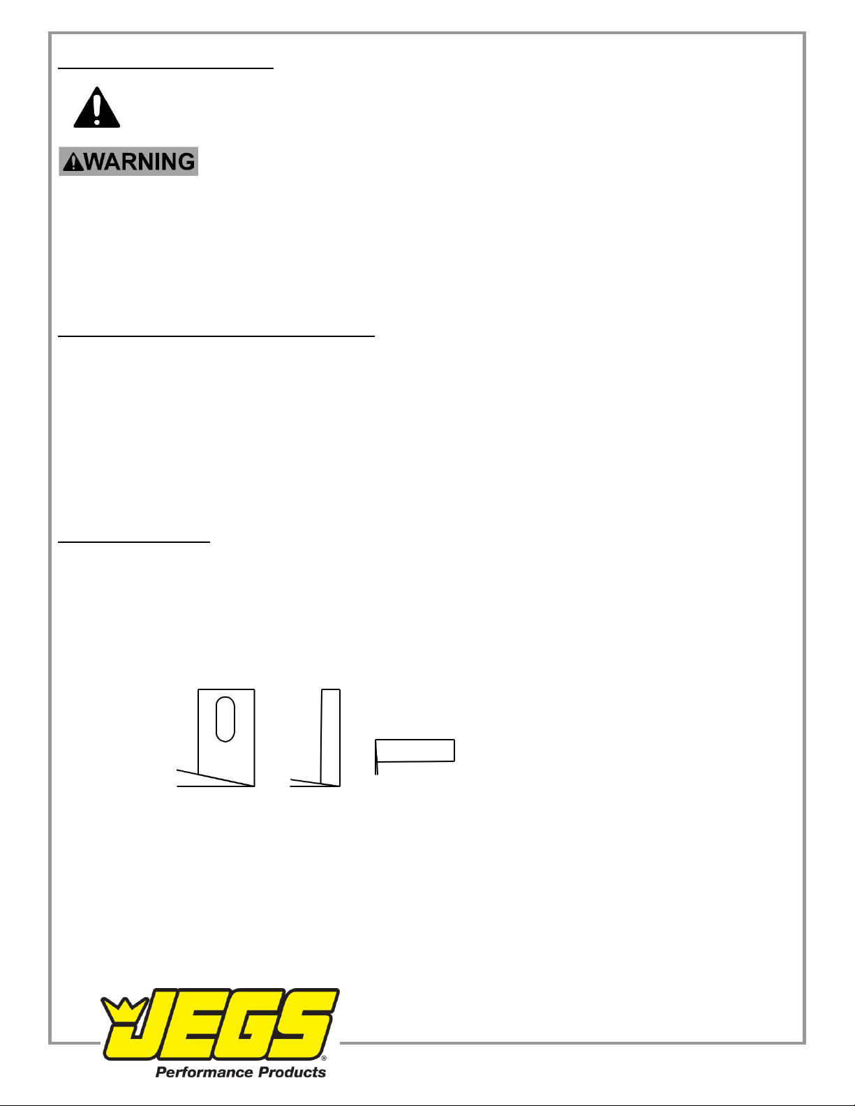
Gap Adjustment
Gap is the horizontal clearance between the Upper and Lower Blades. To ensure a clean cut, the gap should be
adjusted according to the thickness of the material being cut.
1. The formula for determining the proper gap is material thickness in mm divided by 5. For example: 18 gauge
stainless steel is 1.2 mm thick. 1.2 ÷ 5 = 0.24 (gap).
Upper
Blade
Gap Lower Blade
Figure B
2. Measure the gap between the blades using a feeler gauge set (not included).
3. If the gap needs adjustment:
a. Slightly loosen the Lower Socket Screw (4)
b. Slightly loosen the Nut (7) on the
Adjusting Screw (8) by holding the Adjusting Screw still while loosening the Nut. Nut
c. Turn the Adjusting Screw until desired gap is achieved. Adjusting
d. Hold the Adjusting Screw still while tightening the Nut. Lower Socket Screw
e. Then, tighten the Lower Socket Screw. Screw (not shown)
Figure C
Workpiece and Work Area Set Up
1. Designate a work area that is clean and well lit. The work area must not allow access by children or pets to
prevent distraction and injury.
2. Route the power cord along a safe route to reach the work area without creating a tripping hazard or exposing
the power cord to possible damage. The power cord must reach the work area with enough extra length to
allow free movement while working.
3. Secure loose workpieces using a vise or clamps (not included) to prevent movement while working.
4. There must not be objects, such as utility lines, nearby that will present a hazard while working.
9
1-800-345-4545 jegs.com

General Operating Instructions
TO PREVENT SERIOUS INJURY:
Wear ANSI-approved safety goggles and heavy-duty work gloves during use.
1. BEFORE EACH USE, lubricate the Shears:
a. Make sure that the Power Switch is in the OFF position, then plug in the Shears.
b. Turn on the Shears and run for one minute.
c. Turn off the Shears, then unplug from outlet.
d. Put 3-4 drops of light machine oil in the Oil Port.
e. Turn the tool on its side, and put 1-2 drops of light machine oil above the Upper Blade.
2. Make a few practice cuts on scrap material before cutting your workpiece.
3. Make sure that the Power Switch is in the OFF position, and then plug in the Shears.
4. Turn on the Shears.
Note: To prevent damage to the blades, do not cut across a welded seam.
5. To cut material, fit the Guide over the edge of the material, and move the tool slowly forward along the
desired cut line.
6. To prevent accidents, turn off the tool and unplug it after use. Clean, and then store the tool indoors out of
children’s reach.
Oil Port
Area above
Upper Blade
Figure D
10
1-800-345-4545 jegs.com
Maintenance and Servicing
Procedures not specifically explained in this manual must be
performed only by a qualified technician.
TO PREVENT SERIOUS INJURY FROM ACCIDENTAL OPERATION:
Make sure that the Switch is in the off-position and unplug the tool from its electrical
outlet before performing any procedure in this section.
TO PREVENT SERIOUS INJURY FROM TOOL FAILURE:
Do not use damaged equipment. If abnormal noise or vibration occurs, have the problem corrected before
further use.
Cleaning, Maintenance, and Lubrication
1. BEFORE EACH USE, inspect the general 2. AFTER USE, wipe external surfaces
condition of the tool. Check for: of the tool with clean cloth.
•loose hardware,
•misalignment or binding of moving parts,
•damaged cord/electrical wiring,
•cracked or broken parts, and
•any other condition that may affect its
safe operation.
Sharpening Blades
When sharpening the Blades, maintain
original angles. (See Figure E)
Upper Blade Upper Blade Lower Blade
12° 8° 4°
Figure E
11
1-800-345-4545 jegs.com
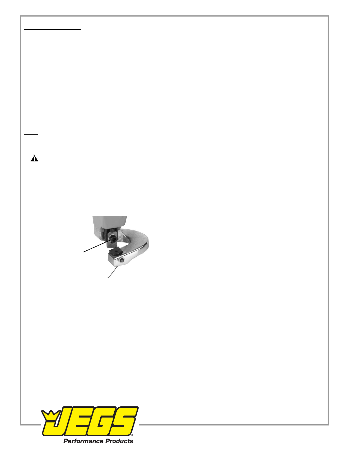
Replacing Blades
1. Remove Upper Blade:
a. Remove Upper Socket Screw (13), Spring Washer (5) and Washer (6).
b. Then, remove Upper Blade.
2. Remove Lower Blade:
a. Remove Lower Socket Screw (4), Spring Washer (5) and Washer (6).
b. Then, remove Lower Blade.
3. Installing new or sharpened Blades:
Note: To maintain a consistent cutting edge, install new Blades in sets.
a. Install Upper Blade first and tighten securely.
b. Then, install Lower Blade and tighten enough to allow gap adjustment.
c. Adjust gap according to Gap Adjustment on page 9.
Note: The screw above the Upper Blade is factory-set.
4. Make a few practice cuts on scrap material before cutting your workpiece.
5. WARNING! If the supply cord of this power tool is damaged, it must be replaced only by a qualified
service technician.
Upper Socket
Screw
Lower Socket
Screw
(not shown)
12
1-800-345-4545 jegs.com

Troubleshooting
Problem
Possible Causes
Likely Solutions
Tool will not start.
1.
Cord not connected.
1.
Check that cord is plugged in.
2.
No power at outlet.
2.
Check power at outlet. If outlet is unpowered,
turn off tool and check circuit breaker.
If breaker is tripped, make sure circuit is right
capacity for tool and circuit has no other loads.
3.
Internal damage or wear.
3.
Have qualified technician service tool.
(Carbon brushes or
Switch for example.)
Tool operates slowly.
1.
Forcing tool to work too fast.
1.
Allow tool to work at its own rate.
2.
Extension cord too long or cord
2.
Eliminate use of extension cord. If an extension
diameter too small.
cord is needed, use one with the proper diameter
for its length and load. See Extension Cords
in Grounding section on page 6.
Performance
1. Carbon brushes worn
1.
Have qualified technician replace brushes.
decreases over time.
or damaged.
2.
Blades dull or damaged.
2.
Keep blades sharp. Replace as needed.
Excessive noise
Internal damage or wear. (Carbon
Have qualified technician service tool.
or rattling.
brushes or bearings, for example.)
Overheating.
1.
Forcing tool to work too fast.
1.
Allow tool to work at its own rate.
2.
Blades dull or damaged.
2.
Keep blades sharp. Replace as needed.
3.
Blocked motor housing vents.
3.
Wear ANSI-approved safety goggles and
NIOSH-approved dust mask/respirator while
blowing dust out of motor using compressed air.
4.
Motor being strained by long or
4.
Eliminate use of extension cord. If an extension
small diameter extension cord.
cord is needed, use one with the proper diameter
for its length and load. See Extension Cords
in Grounding section on page 6.
Follow all safety precautions whenever diagnosing or servicing the tool.
Disconnect power supply before service.
13
1-800-345-4545 jegs.com

Parts List and Diagram
PLEASE READ THE FOLLOWING CAREFULLY
THE MANUFACTURER AND/OR DISTRIBUTOR HAS PROVIDED THE PARTS LIST AND ASSEMBLY DIAGRAM IN
THIS MANUAL AS A REFERENCE TOOL ONLY. NEITHER THE MANUFACTURER NOR DISTRIBUTOR MAKES
ANY REPRESENTATION OR WARRANTY OF ANY KIND TO THE BUYER THAT HE OR SHE IS QUALIFIED TO
MAKE ANY REPAIRS TO THE PRODUCT, OR THAT HE OR SHE IS QUALIFIED TO REPLACE ANY PARTS OF
THE PRODUCT. IN FACT, THE MANUFACTURER AND/OR DISTRIBUTOR EXPRESSLY STATES THAT ALL
REPAIRS AND PARTS REPLACEMENTS SHOULD BE UNDERTAKEN BY CERTIFIED AND LICENSED
TECHNICIANS, AND NOT BY THE BUYER. THE BUYER ASSUMES ALL RISK AND LIABILITY ARISING OUT OF
HIS OR HER REPAIRS TO THE ORIGINAL PRODUCT OR REPLACEMENT PARTS THERETO, OR ARISING OUT
OF HIS OR HER INSTALLATION OF REPLACEMENT PARTS THERETO.
Parts List
Part
Description
Q
Qty
Part
Description
Qty
1
Socket Screw (M12x25)
1
30
Circlip (10)
1
2
Lower Socket Screw (M6x16)
1
31
Needle Bearing
1
3
Spring Washer (Ø6)
1
32
Stem Gear
1
4
Washer (Ø6)
1
33
Key (3x8)
1
5
Adjusting Screw (M5x16)
1
34
Gear
1
6
Nut (M5)
1
35
Ball Bearing (626)
1
7
Lower Blade
1
36
Screw
4
8
Spring Pin (M4x30)
2
37
Intermediate Cover
1
9
Guide
1
38
Ball Bearing (628)
1
10
Shaft Sleeve
1
39
Motor Armature
1
11
Lock Screw (M4x12)
1
40
Power Switch Drawbar
1
12
Upper Socket Screw (M6x13)
1
41
Power Switch Push Plate
1
13
Spring Washer (Ø6)
1
42
Socket Lead Screw (M4x58)
2
14
Washer (Ø6)
1
43
Stator
1
15
Upper Blade
1
44
Ball Bearing (607)
1
16
Arbor
1
45
Rubber Washer
1
17
Straight Pin
1
46
Housing
1
18
Connecting Bar
1
47
Brush Holder
2
19
Socket Screw (M5x50)
2
48
Carbon Brush
2
20
Spring Washer (Ø4)
4
49
Screw
2
21
Gear Cover
1
50
Internal Power Switch
1
22
Ball Bearing (628)
1
51
Screw
2
23
Needle Bearing
1
52
Strain Relief
1
24
Eccentric Shaft
1
53
Cover Plate
1
25
Straight Key (4x8)
1
54
Power Cord Sleeve
1
26
Ball Bearing (6201)
1
55
Housing
1
27
Circlip (932)
1
56
Screw
1
28
Bearing
1
57
Power Cord with Plug
1
29
Gear
1
58
Hex Key (not shown)
1
Note: If product has no serial number, record month and year of purchase instead.
Note: Some parts are listed and shown for illustration purposes only,
and are not available individually as replacement parts.
14
1-800-345-4545 jegs.com
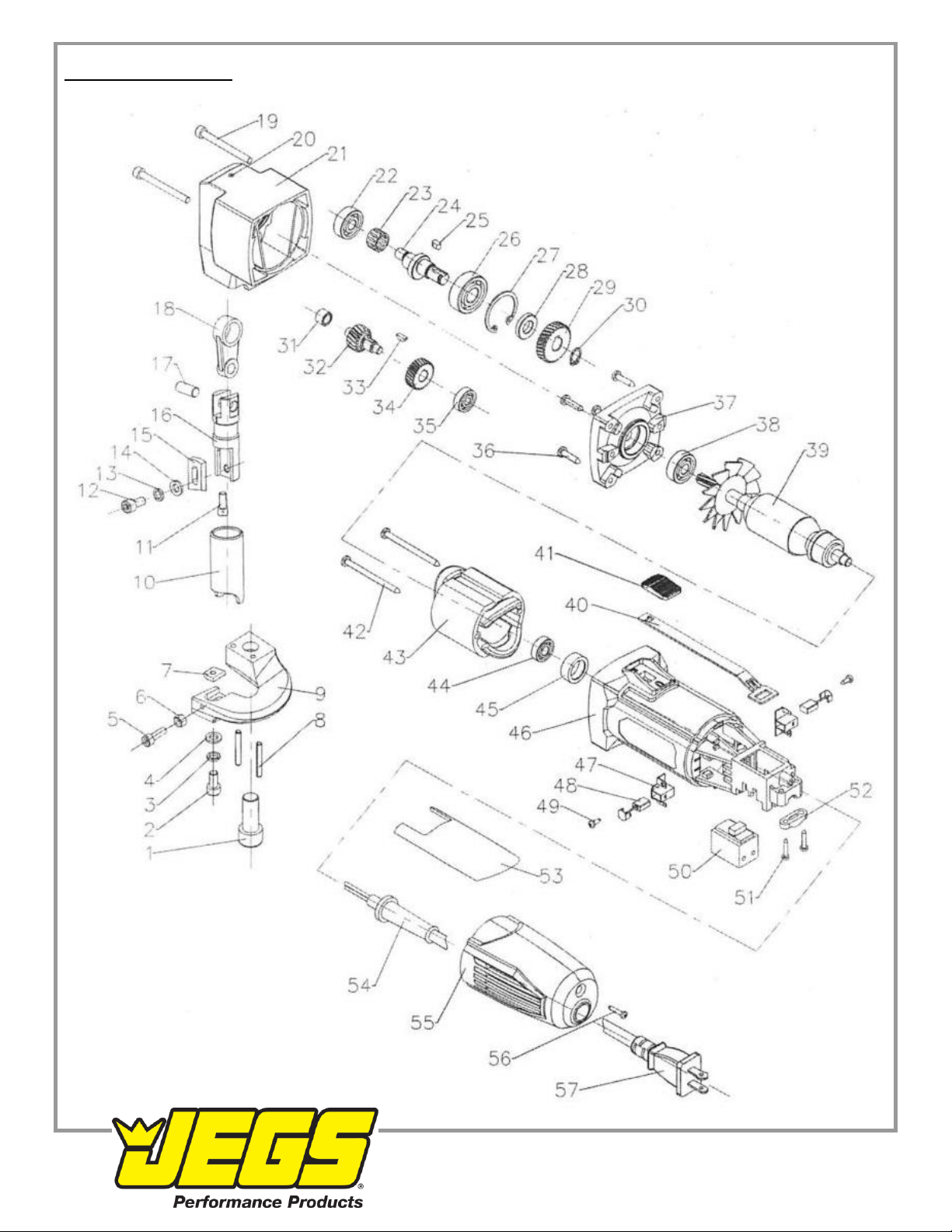
Assembly Diagram
15
1-800-345-4545 jegs.com
Table of contents
Other Jegs Power Tools manuals


