JENCO 692 User manual

OPERATION MANUAL
THE JENCO MODEL 692
PH TRANSMITTER
JENCO
ELECTRONICS, LTD.
MANUFACTURER OF PRECISION INSTRUMENTS

1
INTENDED USE AND GENERAL INTRODUCTION
The models 3672, 3673 and 3675 are precise instruments for the measurement and control
of pH and mV (ORP).
Two output relays are provided in the model 3675 for ON/OFF control. The isolated 4-20
mA output current of the model 3675 covers the input control range of 0 to 14 pH and 0 to
1400 mV.
A front panel programmable HIGH/LOW ALARM relay is provided in the models 3672
and 3673.
The isolated 4-20 mA output of the model 3672 can be set for a input control span of any
2 to 14 pH (200 to 1400 mV), via the front panel CONTROL SET POINT and SPAN ADJ
controls. The output 4-20 mA current can be selected for increasing or decreasing values
for increasing pH and mV (ORP) inputs. The isolated 4-20 mA output current of the
model 3672 covers the input control range of 0 to 14.00 pH and ±1999 mV.
The output pulse frequency of the model 3673 is proportional to the ion concentration,
over a preset proportional band of 2 pH and 200 mV. The pulse frequency output can be
selected for increasing or decreasing pulse rate for increasing pH and mV (ORP) inputs.
The maximum pulse frequency can be adjusted by the front panel PULSE RATE
ADJUST control. The pulse frequency output of the model 3673 covers the input control
range of 0 to 14.00 pH and ±1999 mV.

2
A large LCD display is used for readability under bright ambient conditions.
The models 3672, 3673 and 3675 are housed in a rugged 1/4 DIN plastic case, allowing it
to fit into standard panel cut-outs as well as the most commonly available industrial
weatherproof and environmental housings.
INITIAL INSPECTION
Carefully unpack the instrument and accessories. Inspect for damage in shipment. If any
damage is found, NOTIFY YOUR JENCO DISTRIBUTOR IMMEDIATELY. All
packing materials should be saved until satisfactory operation is confirmed.

3
FRONT PANEL FORMAT FOR THE MODEL 3672
1. LCD display
2. CONTROL SET POINT switch
3. CONTROL SET POINT LED
4. CONTROL SET POINT control
5. OUTPUT CURRENT SELECT switch
6. pH STANDARDIZATION control
7. pH SLOPE control
8. 4-20 mA SPAN ADJUST control
9. ALARM SET POINT switch
10. ALARM SET POINT LED
11. ALARM SET POINT control
12. ALARM SET POINT HIGH /LOW
SELECT switch
FIGURE 1A

4
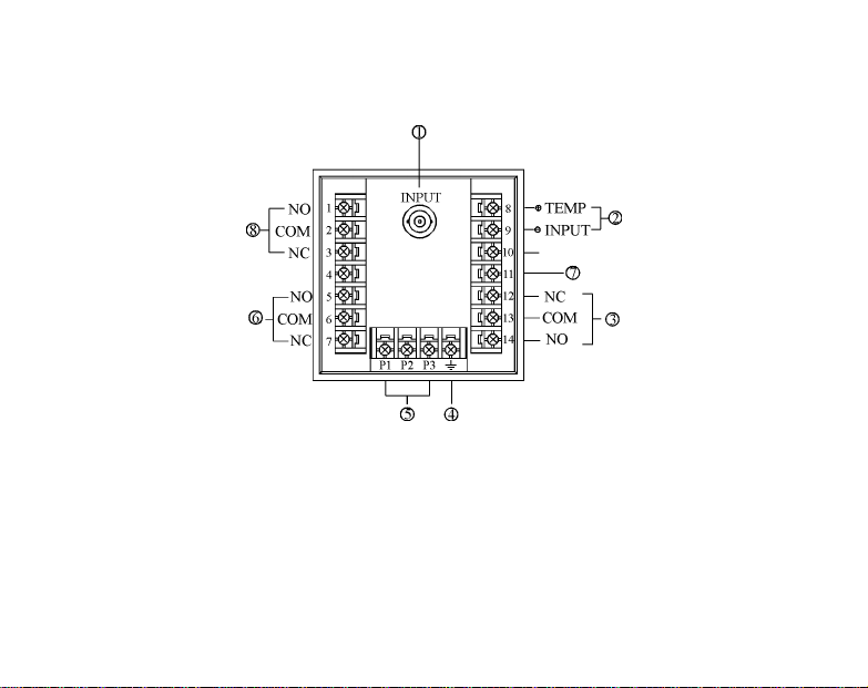
REAR PANEL FORMAT FOR THE MODELS 3672
1. pH/mV electrode BNC input
2. ATC probe input
3. Isolated 4-20 mA output
4. Reference electrode input
5. EARTH ground
6. AC power input
7. ALARM output relay
8. CONTROL output relay
FIGURE 2A

5
FRONT PANEL FORMAT FOR THE MODEL 3673
1. LCD display
2. PULSE RATE ADJUST control
3. CONTROL SET POINT switch
4. CONTROL SET POINT LED
5. CONTROL SET POINT control
6. PULSE FREQUENCY HIGH/LOW
SELECT switch
7. pH STANDARDIZATION control
8. pH SLOPE control
9. DEAD AND ADJUST control
10. ALARM SET POINT switch
11. ALARM SET POINT LED
12. ALARM SET POINT control
13. ALARM SET POINT HIGH/LOW
SELECT switch
FIGURE 1B
6
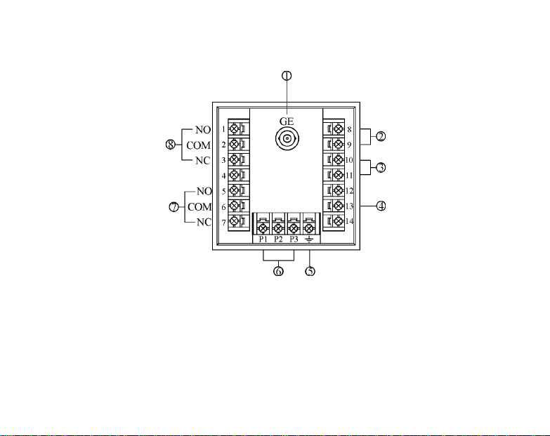
REAR PANEL FORMAT FOR THE MODELS 3673
1. pH/mV electrode BNC input
2. ATC probe input
3. Pulse frequency output
4. EARTH ground
5. AC power input
6. ALARM output relay
7. Reference electrode input
8. CONTROL output relay
FIGURE 2B

7
FRONT PANEL FORMAT FOR THE MODELS 3675
1. LCD display
2. HIGH ALARM SET POINT switch
3. HIGH ALARM SET POINT LED
4. HIGH ALARM SET POINT control
5. pH STANDARDIZATION control
6. pH SLOPE control
7. LOW ALARM SET POINT switch
8. LOW ALARM SET POINT LED
9. LOW ALARM SET POINT control
FIGURE 1C
8
REAR PANEL FORMAT FOR THE MODELS 3675
1. pH/mV. electrode BNC input
2. ATC probe input
3. Isolated 4-20 mA output
4. Reference electrode input
5. EARTH ground
6. AC power input
7. HIGH ALARM output relay
8. LOW ALARM output relay
FIGURE 2C
9
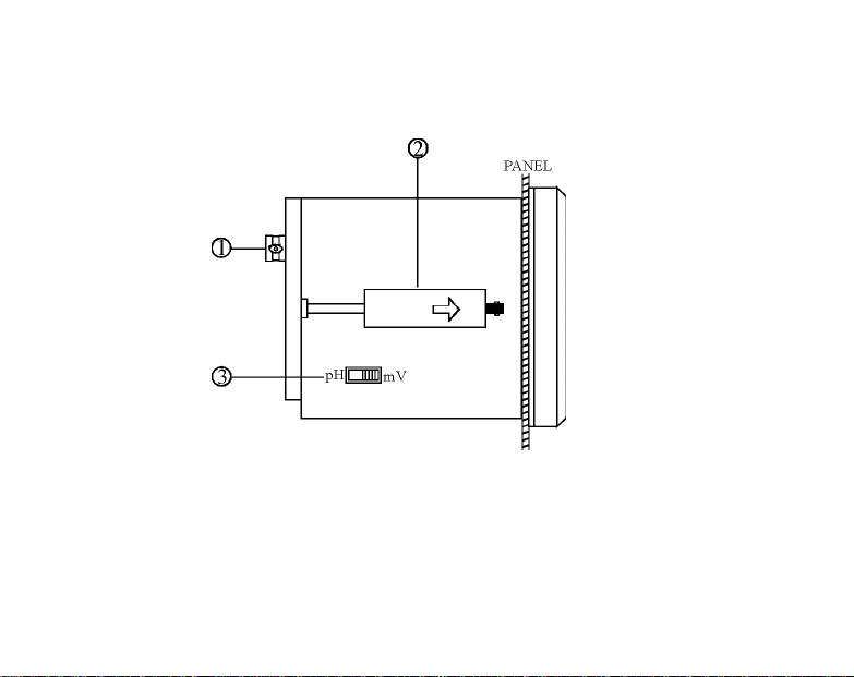
SIDE VIEW
1. pH/mV input BNC connector
2. Mounting bracket 3.pH/mV SELECT switch
FIGURE 3

10
TEMPERATURE COMPENSATION
The models 3672, 3673 and 3675 are designed to be used with a PT-100 RTD temperature
probe for automatic temperature compensation, ATC, operations. The alpha value of the
PT-100 element is 0.00385.
A precision 0.1% resistor can be connected across the ATC input terminals to simulate a
fixed process temperature.

11
Temperature in ℃Resistor value in Ohms
0 100.00
10 103.90
20 107.79
25 109.73
30 111.67
40 115.54
50 119.40
60 123.24
70 127.07
80 130.89
90 134.78
100 138.50
TABLE 1

12
REAR PANEL CONNECTION SCHEME
(Refer to FIGURE 1A/1B/1C and FIGURE 2A/2B/2C)
1. Connect the AC line to the rear terminals of the instrument. The instrument can be
powered by 115 VAC or 230 VAC, 50/60 Hz. Make sure that the Earth terminal is
connected to the earth lead of the AC power line.
2. Connect the proper load to the output relays. Be sure that the load does not exceed the
relay rating, 5 Amp at 115 VAC and 2.5 Amp at 230 VAC for RESISTIVE load only.
3. Set the pH/mV switch to the position for pH or mV operations. (Refer to FIGURE 3)
4. Load connections
Models 3672/3675
Connect the proper load to the 4-20 mA output terminals. Make common mode
voltage does not exceed 500 VDC.
Model 3673
Connect the pulse pump input leads to the output terminals of the pulse frequency
output. The common mode voltage is not to exceed 1500 VDC.
5. Increasing/decreasing outputs for increasing pH (mV) inputs
Model 3672 Refer to pages 10, 11, 12.
Set the OUTPUT CURRENT SELECT switch to the desired postion.
Model 3673 Refer to pages 10, 11, 12, 13.
Set the PULSE FREQUENCY SELECT switch to the desired position.
6. Electrode connections

13
6.1 Combination pH (mV) electrodes
Connect the pH (mV) electrode cable to the pH/mV electrode BNC input
connector.
6.2 Separate pH (mV) electrodes
Connect the working electrode to the pH/mV electrode BNC input connector.
Connect the reference electrode to the Reference input terminal.
7. Temperature compensation input connections
7.1 ATC mode
Connect the automatic temperature compensation, ATC, probe to the ATC input
terminals.
7.2 A percision 0.1% resistor can be connected across the ATC terminals to simulate
a fixed process temperature. (Refer to TABLE 1)
MOUNTING PROCEDURE
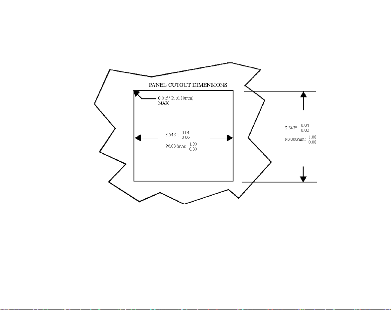
1. Make a cutout on any panel, with a thickness of 1/16 in. (1.5 mm) to 3/8 in. (9.5 mm).
(Refer to FIGURE 4)
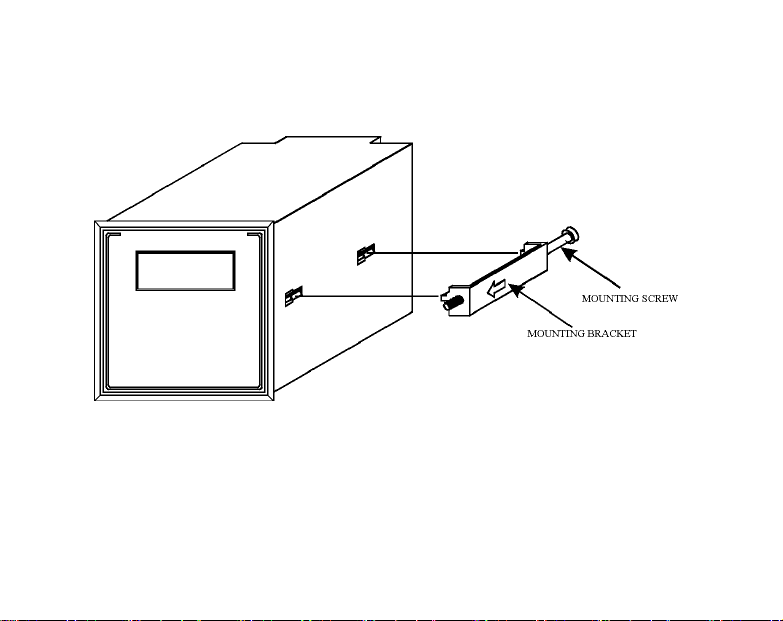
2. Remove the mounting brackets assembly from the panel meter and insert the panel
meter into the cutout. (Refer to Figure 5)
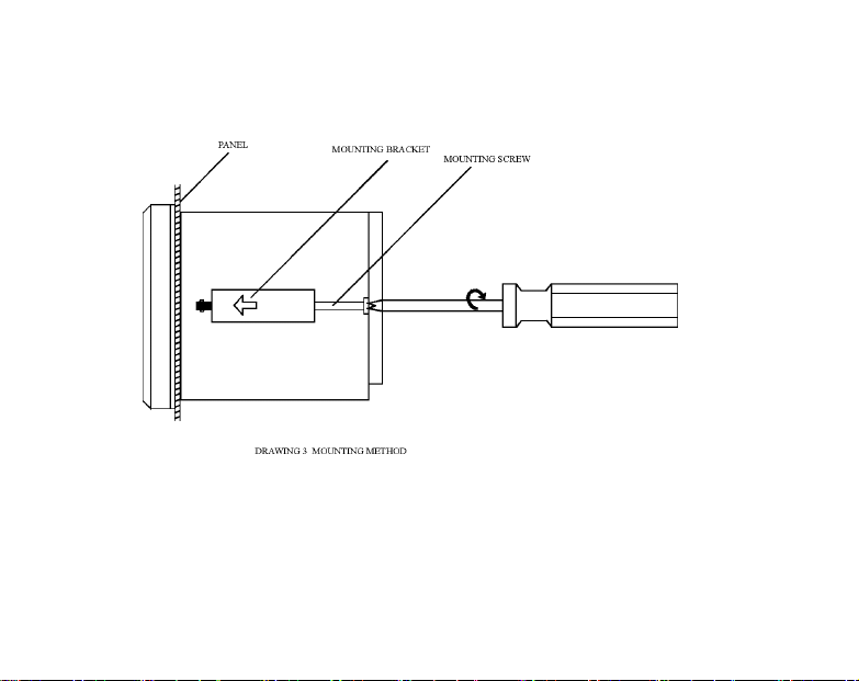
3. Replace the mounting brackets assembly onto the panel meter and fasten the
mounting screws to secure the panel meter to the mounting panel. (Refer to Figure 6)
14
Panel Cutout
FIGURE 4
15
Panel Meter With Mounting Bracket And Screw
FIGURE 5
16
Mounting Method
FIGURE 6

17
pH CALIBRATION
Refer to REAR PANEL CONNECTION SCHEME, pages 11, 12.
Refer to TEMPERATURE COMPENSATION, page 10.
1. Rinse the pH electrode and ATC probe with distilled water.
2. Measure the temperature of the buffer 7 solution with a precision thermometer.
3. Immerse the pH electrode and ATC/TEMP probe in buffer 7. Allow sufficient time
for the pH electrode and ATC probe to reach temperature equilibrium with the buffer
7.
4. Adjust the STAND control for the instrument to display the buffer value
corresponding to the temperature measured in 2. Refer to TABLE 2.
5. Remove the pH electrode and ATC probe from buffer 7 and rinse with distilled water.
6. Measure the temperature of a second buffer with a precision thermometer.
7. Immerse the pH electrode and ATC probe in the second buffer .For accurate pH
measurements, the second buffer should be close in pH and temperature values to
process under test. In practice, pH buffers 4 and 10 are commonly used.
8. Adjust the SLOPE control for the instrument to display the buffer value
corresponding to the temperature measured in 6. Refer to TABLE 2.
9. Remove the pH electrode and ATC probe from the second buffer and rinse with
distilled water. The instrument is dual point calibrated and ready for measurements.

18
TEMPERATURE COEFFICIENT OF THE pH BUFFERS
BUFFERS
℃10.01 7.00 4.01
0 10
.
32
7.
11 4
.
00
5 10
.
25
7.
08 4
.
00
10 10
.
18
7.
06 4
.
00
15 10
.
12
7.
03 4
.
00
20 10
.
06
7.
01 4
.
00
25 10
.
01
7.
00 4
.
01
30
9.97
6
.9
84
.
02
35
9.9
36
.9
84
.
02
40
9.
8
9
6
.97
4
.
03
45
9.
86 6
.97
4
.
04
50
9.
83 6
.97
4
.
06
55
9.
80 6
.97
4
.
0
7
60
9.7
86
.9
84
.
10
TABLE 2

19
ISOLATION VOLTAGE
The differential voltage between the outputs and the load should not exceed the maximum
values. Exceeding the maximum values may cause permanent damage to the instrument
and load.
1. Relay output
The maximum isolation voltage of the relay output contacts is 1500 VDC. The
voltage differential between the relay output contacts and the load should not exceed
1500 VDC.
2. Current output
The maximum isolation voltage of the 4-20 mA output is 500 VDC. The voltage
differential between the 4-20 mA output and the load should not exceed 500 VDC.
OUTPUT LOAD
1. Relay output
The current through the relay output contacts should not exceed 5 Amp at 115 VAC
and 2.5 Amp at 230 VAC in order hot to cause permanent damage the relay contacts.
This rating is specified for RESISTIVE loads only.
2. Current output
The maximum load is 550 ohms. Output current inaccuracies may occur for load
impedance in excess of 550 ohms.
Table of contents
Other JENCO Transmitter manuals


