JENCO 3351 User manual

Operation Manual
MODEL 3351
Microcomputer Based Conductivity/Resistivity Transmitter
JENCO ELECTRONICS, LTD.
MANUFACTURER OF PRECISION INSTRUMENTS

1
CONTENTS
GENERAL INTRODUCTION………………………………………..………....................2
INITIAL INSPECTION……...………………..................................................................2
USING THE JENCO MODEL 3351……......................................................................3
A. Mounting procedure.....................................................................................3
B. Front panel....................................................................................................5
C. LCD screen....................................................................................................7
D. Rear connectors...........................................................................................9
E. Measure mode.............................................................................................10
F. Setting mode................................................................................................11
G. RS485 Setting mode...................................................................................16
H. Conductivity/Resistivity calibration mode..............................................17
ERROR DISPLAY AND TROUBLESHOOTING……………..……….........................18
SPECIFICATIONS……………..………………………………………........................20
WARRANTY……………..………...............................................................................22

2
GENERAL INTRODUCTION
Thank you for selecting the JENCO Model 3351. The 3351 Conductivity/Resistivity
Transmitter is a rugged microprocessor based instrument assembled in a watertight 1/8
DIN case, designed for use in laboratories and process control applications.
The system displays Conductivity / Resistivity or Temperature status in one large LCD
screen.
The model 3351 microprocessor performs a self-diagnostic routine every time the
user resets the unit, After device resets, it will provide the user with basic information
on the stability of the instrument.
A setup CD is included in the instrument package. After installation, it allows the user to
communicate with the instrument by a computer through RS485 serial connection.
INITIAL INSPECTION
Carefully unpack the unit and accessories. Inspect for damages made in shipment. If
any damage is found, notify your Jenco representative immediately. All packing
materials should be saved until satisfactory operation is confirmed.

3
USING THE JENCO MODEL 3351 ERVIEW
A. Mounting Procedure
PANEL CUTOUT DIM ENSIONS
45.0
1.772"
92.0 3.622"
0.813 0.032
0.61
0.024
0.00
0.000
0.000 0.000
±±
±
±
DRAWING 1
1. Make a cutout on any panel, with a
thickness of 1/16 inch (1.5mm) to
3/8 inch (9.5mm). Refer to
DRAWING 1.
DRAWING 2
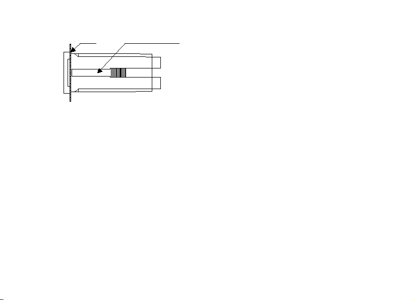
2. Remove the mounting assembly
from the controller and insert the
controller into the cutout. Refer to
DRAWING 2.
M ounting Brackets
4
Panel M ounting brackets
DRAWING 3
3. Replace the mounting bracket
assembly onto the controller and
secure the controller to the
mounting panel. Refer to
DRAWING 3.
【
Note
】
:
If the equipment is used in a manner not specified by the manufacturer, the protection
provided by the equipment may be impaired.

5
B. Front Panel
The front panel consists of a 4-digit LCD display and 4 keys.
1. [ MODE ] key:
1a. In the Measure mode, this key will switch the display in sequence from
Conductivity, Temperature and back to Conductivity again or from Resistivity,
Temperature and back to Resistivity again.
1b. In the Calibration/Setting mode, pressing this key for three seconds will
move you back to the previous parameter in the case when recalibration / resetting
is required.

6
2. [ UP ] key:
2a. In the Calibration mode, pressing this key will increase the numeral increment.
In the Setting mode, pressing this key will show the next possible option and
increase the numeral increment.
2b. In the Measure mode, pressing this key and [ENTER] key at the same time,
the unit will enter the Calibration mode.
3. [ DOWN ] key:
3a. In the Calibration mode, pressing this key will decrease the numeral
increment. In the Setting mode, pressing this key will show the next possible
option and decrease the numeral increment.
3b. In the Measure mode, pressing this key and [ENTER] key at the same time,
the unit will enter the Setting mode.
4. [ ENTER ] key:
In any mode where the user can change the settings, pressing this key will save
the new settings. If no change has been made then pressing this key will just lead
7
the user to the next setting.
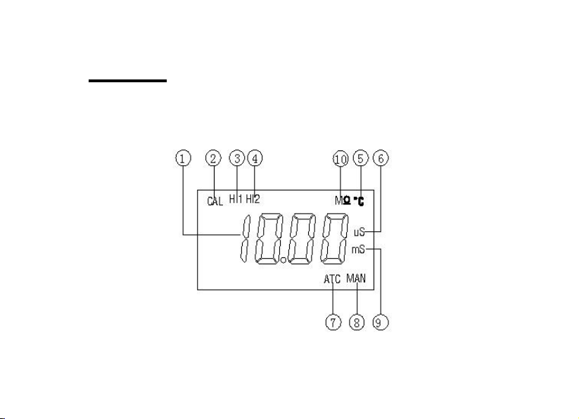
C. LCD screen

8
1. Major LCD display.
2. CAL – This icon will be displayed if the meter is in the Calibration/Setting mode.
3. HI1 – This icon will be displayed if the meter is in the Setup Identification (ID).
4. HI2 –This icon will be displayed if the meter is in the RS485 Communication
Setup
5. ℃–Temperature and unit display.
6. uS – Unit indicator.
7. ATC –This icon will be displayed when a temperature probe is connected.
8. MAN –This icon will be displayed if the no temperature probe is not connected.
9. mS – Unit indicator.
10. MΩ–Unit indicator.

9
D. Rear connectors
*Specify “L’ = “Live Lead” 100 to 230 VAC Volts and “N” = “Neutral Lead”
1. Connect the AC line to the rear of the instrument. The model 3351 can be powered
by 100~240V AC source at 50/60 HZ. Make sure the EARTH connector is
connected to the earth lead of the AC power line.

10
2. The metallic shield of the conductivity electrode must be connected to the "GND",
otherwise the readings would be unstable.
【
Note
】
:
(1) Make sure that the power is unplugged before wiring your probes etc.
(2) Make sure you connect the AC power cord to the correct AC terminals. Incorrect
connection may damage the unit permanently.
E. Measure mode
Turning on the unit will always display the Measure mode. This instrument is designed
to provide 2 distinct measurements: Conductivity, Temperature or Resistivity,
Temperature.
MODE
m S
ATC ATC
M
ATC ATC
MODE MODE
MODE
or
1. Conductivity – Current conductivity of the solution.

11
2. Resistivity –Current resistivity of the solution.
3. Temperature – Current temperature of the solution.
【
Note
】
:Pressing [MODE] key in the Measure mode will cycle the display between
the two modes above.
F. Setting mode
Pressing [DOWN] key and [ENTER] key at the same time, the meter will enter into the
Setting mode.
1. Temperature compensation select:
+ ENTER
Tem perature coefficient select
M AN
CAL
ATC
CAL
ENTER ENTER
12
Pressing [UP] key or [DOWN] key in this screen will cycle the display between 01
(Thermistor: 10k ohm), 02 (Manual) modes above.
Select the preferred temperature compensation mode, press [ENTER] key to save,
and enter the next setting screen.
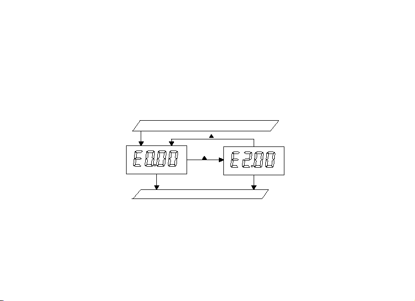
2. Temperature Coefficient select:
Tem perature com pensation select
probe B asic cell constant select
EN TER
EN TER EN TER
C A L C A L
Pressing [UP] key or [DOWN] key in this screen will cycle the display between
E2.00, E0.00 above.
Select the preferred coefficient, press [ENTER] key to save, and enter the next
setting screen.
13
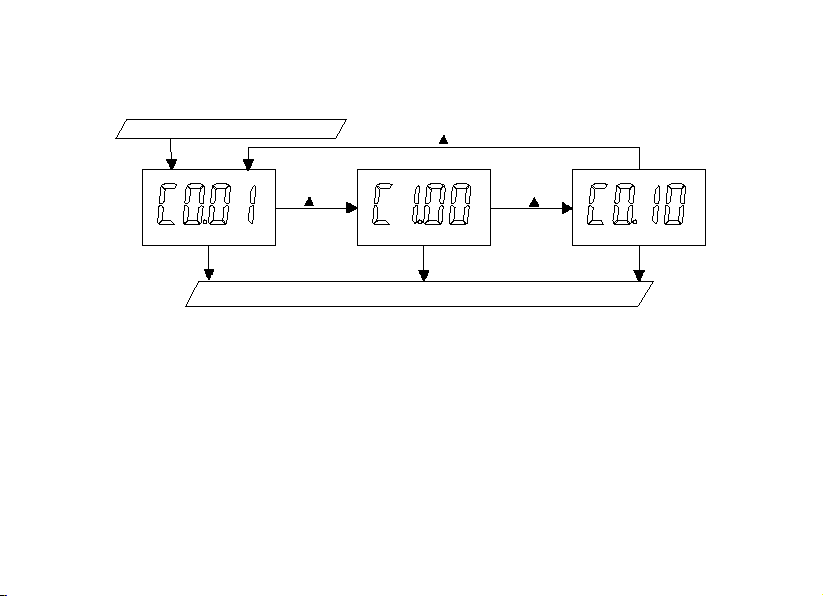
3. Probe Basic cell constant select:
Tem perature coefficient select
Range select
ENTER
ENTER ENTER ENTER
CAL CALCAL
Pressing [UP] key or [DOWN] key in this screen will cycle the display from C1.00,
C0.10 to C0.01 basic cell constant above.
Select the preferred basic cell constant, press [ENTER] key to save, and enter the
next setting screen.

14
4. Range select:
Pressing [UP] key or [DOWN] key in this screen will cycle the display from
CF01/0.000~1.999uS/cm, CF02/0.00~19.99uS/cm, CF03/0.000~1.999MΩ,
CF04/0.00~19.99MΩ(Basic cell K is C0.01) or CF01/0.00~19.99uS/cm,
CF02/0.0~199.9uS/cm(Basic cell K is C0.10) or CF01/0.0~199.9uS/cm,
CF02/0~1999uS/cm, CF03/0.00~19.99mS/cm (Basic cell K is C1.00) above.
Select the preferred basic cell constant , press [ENTER] key to save, and enter the
next setting screen.

15
EN TER
EN TER EN TER EN TER
C A L
C A L C A L C A L
ID m odel select

16
G. RS485 Setting mode
A setup CD is included in the instrument package. After installation, it allows the
user to communicate with the instrument by a computer through RS485 serial
connection.
It is recommended to use a standard shield twisted pair cable for optimum
RS-485 communications.
1.Setup Identification (ID)
Press both [Down] and [Enter] button at the same time. The “CAL” shall display on
the upper left corner of the screen. When “HI1” is shown on the screen, user
enters into the “ID Option” interface. Press [Up] or [Down] key for choosing the
identification (ID) number. Press [Enter] and store the identification number in the
memory. After successfully storing the identification the system automatically
enters into the “RS485 Communication Setup” interface.

17
2.RS485 Communication Setup
This unit uses MODBUS protocol to transmit data over RS-485. After entering the
“RS485 Communication Setup” interface, the “HI 2” shall lit up. Press [Up] or
[Down] key and choose between the three MODBUS protocol options of “None”,
“Odd” and “Even”. Press [Enter] and return to the measurement interface.
H. Conductivity/Resistivity Calibration mode
The model 3351 uses 1-point calibration for conductivity or resistivity.
In the Measure mode, pressing [UP] key and [ENTER] key at the same time to allow
the meter to go to the Conductivity / Resistivity calibration mode.
At the Conductivity / Resistivity calibration mode, the “CAL” icon and a
conductivity/resistivity reading will display. Rinse the conductivity probe in distilled
water and immerse it into the standization solution. Allow temperature reading to
stabilize, press [UP] key or [DOWN] key to change this reading to that of the
standization solution value, then press [ENTER] key to save. Calibration is now
completed.

18
ERROR DISPLAY AND TROUBLESHOOTING ERVIEW
Conductivity/
Resistivity
Display
Temperature
Display
Display
Mode
Possible cause(s)
[Action(s)]
"OvEr"
-10.0~120.0°C
Measure
mode
Reading is over the specified
range.
[Change range to higher level]
“Undr”
-10.0~120.0°C
Measure
mode
Reading is under user specified
range.
[Change range to lower level]
[Immerse the conductivity probe
into standization solution.]
"OvEr"
"OvEr"
Measure
mode
a. Temperature > 120.0°C.
[Bring standization solution to

19
lower temperature.]
[Replace temperature probe.]
b. No temperature sensor.
[Adjust the manual temperature to
-10~120°C.]
"OvEr"
“Undr”
Measure
mode
a. Temperature < -10.0°C.
[Bring standization solution to
higher temperature.]
[Replace temperature probe.]
b. No temperature sensor.
[Adjust the manual temperature to
-10~120°C.]
Table of contents
Other JENCO Transmitter manuals


Popular Transmitter manuals by other brands


Lamtec
Lamtec Lambda LS2-K quick reference

Sensorex
Sensorex TX2000 Operation manual

RKI Instruments
RKI Instruments 65-2335RK Operator's manual

Broadcast Warehouse
Broadcast Warehouse TX 25/50 Technical manual

Greyline Instruments
Greyline Instruments Tank Farm Transmitter TFT32 user guide

SMC Sierra Monitor
SMC Sierra Monitor IT Series manual