Jenny Reciprocating Air Compressors User manual
Reciprocating
Air
Compressors
Operation and
Maintenance
Manual
Jenny Products, Inc.
850 North Pleasant Avenue
Somerset, PA 15501-1069
Ph:814-445-3400 ●Fx:814-445-2280
www.jennycompressor.com ●info@jennycompressor.com
¤
R
R
R
¤
¤
¤
.

2
Table of Contents
Section 1
Safety and Health Instructions
Safety and Health Instruction for Safe Use....................
Section 2
Introduction and Description
Introduction....................................................................
General Description........................................................
Major Components.........................................................
Reciprocating Air Compressor Assembly.......................
Single Stage and Two Stage Reciprocating Pumps.......
Electric Motor.................................................................
Gasoline Engine.............................................................
Air Control System.........................................................
Constant Run Units - Head Unloader and
Discharge Unloader .........................................
Start-Stop Control Units....................................
Dual Control Units.............................................
Pilot Valve......................................................................
Pressure Switch.............................................................
Pressure Regulator.........................................................
Base/Tank Weldment Assembly.....................................
Magnetic Starter.............................................................
Check Valve...................................................................
Relief Valve....................................................................
Air Intake Filter(s)...........................................................
Section 3
Preparation for Use and Installation
Instructions
General..........................................................................
Inspection of New Equipment.........................................
Servicing of New Equipment..........................................
Lubrication.....................................................................
Air Cleaner.....................................................................
Installation......................................................................
Section 4
Operating Instructions
Operating Controls and Indicators..................................
On/Off Switch....................................................
Receiver Pressure Gauge.................................
Pressure Regulator............................................
Pressure Regulator Gauge...............................
Oil Level Gauge................................................
Pressure Switch......................................
Pilot Valve................................................
Safety Valve............................................
Dual Control Switch.................................
Dual Voltage Switch................................
Preparation for Use..............................................
Lubrication............................................................
Air Cleaner............................................................
Adjusting Regulator...............................................
Connecting and Disconnecting Hoses..................
Draining Air Receiver Condensate.......................
Humid Areas.........................................................
Dual Voltage Switch.............................................
Noise Considerations............................................
Location Considerations
Stationary Compressors..........................
Portable Compressors.............................
Transporting.........................................................
Moving..................................................................
Compatibility........................................................
General Requirements..........................................
Condensate Discharge Piping..............................
Refueling..............................................................
Grounding............................................................
Starting Procedure................................................
Shutdown Procedure............................................
Section 5
Preventive Maintenance
Checking Compressor Pump Oil Level................
Checking Compressor Pump Oil..........................
Checking Safety Relief Valve Operation...............
Checking Air Filter Element..................................
Pilot Valve Cut-Out Pressure Adjustment.............
Pilot Valve Pressure Differential Adjustment........
Pressure Switch Adjustment.................................
Drive Belt Adjustment...........................................
Checking for Air Leaks.........................................
Preventive Maintenance Schedule.......................
Service Information...............................................
Repairs.................................................................
Warranty...............................................................
Free Warning Label Replacement........................
Section 6
Troubleshooting
Troubleshooting....................................................
5
15
15
15
15
16
16
16
16
16
17
17
17
17
18
18
18
18
18
18
20
20
21
21
21
21
25
25
25
25
25
25
25
25
25
25
26
26
26
27
27
27
28
28
28
29
29
29
30
30
30
30
31
31
31
32
34
37
37
38
38
38
39
39
40
41
42
43
43
43
43
45

3
Thank you !
For ordering a JENNY®. Jenny has been a manufacturer of high quality equipment since 1929.
Special attention has been given to every detail of engineering design, perfection of manufacturing
methods, individual part inspection, and thorough testing upon completion to assure the continuous
trouble-free operation of your Jenny.
In short, your Jenny was designed and made by customer-minded workers. If you, for any reason,
fail to f nd that our product serves as you believe it should, you will be doing yourself and us a favor
by telling our Customer Representative, through our Distributor - or direct, just how our product
has failed to please you. Over the years we have found that when troubles are reported by our
customers, both of us prof t. So please help us to serve you properly, which is our f rst desire.
In the march of progress, engineering and design changes are inevitable, therefore, we reserve
the right to vary our designs and/or specif cations without implying that they need to be installed on
previous models. If you have occasion to order parts or request information about your Jenny, be
sure to give machine model number, pump model letter or model number and serial number.
You will f nd this booklet a valuable guide to the proper and safe operation and maintenance of your
new Jenny. It is intended to be used by anyone using or maintaining the equipment. Follow the
instructions carefully and you will assure yourself of the utmost in compressed air eff ciency and
economy.

4
Section 1
Safety and
Health
Instructions

5
SAFETY AND HEALTH INSTRUCTIONS
FOR SAFE USE
In the event that an injury does occur, please seek medical attention at once since the
equipment may cause injuries that are not initially recognized.
1. Use proper electrical power.
Connect unit to a dedicated circuit of the proper voltage, proper rated circuit breaker, and
wired with the proper wire size and number of conductors.
Ensure that all connections are properly tightened. Improper connections could result,
causing damage, injury, or death of the equipment operator.
This machine must be connected in accordance with the National Electric Code (NEC)
Article 422-4 - Ed-31, Except as provided for in NEC 90-4.
This machine must be properly grounded to avoid fatal electrical shock in the event of an
electrical malfunction. A ground connector screw should be fastened into the chassis to
facilitate supplemental grounding as permitted by NEC 250-91.
Do not connect any other equipment to the electrical circuit serving this unit.
Important!
THIS PRODUCT CAN CAUSE SERIOUS INJURY OR
DEATH IF NOT USED IN ACCORDANCE WITH THE
FOLLOWING SAFETY INSTRUCTIONS. WE CAN NOT
ANTICIPATE EVERY POSSIBLE CIRCUMSTANCE
THAT MIGHT INVOLVE A POTENTIAL HAZARD. THE
WARNINGS, CAUTIONS, DANGERS, AND SAFETY
SUGGESTIONS ARE THEREFORE NOT ALL INCLUSIVE.
AS THE OWNER YOU ARE RESPONSIBLE FOR THE
SAFE OPERATION OF THIS EQUIPMENT. ALWAYS
MAKE SURE THAT ANYONE USING THIS EQUIPMENT
HAS READ THIS MANUAL AND FOLLOWS THE SAFETY
WARNINGS TO HELP PREVENT THE POSSIBILITY
OF PERSONAL INJURY TO THE OPERATOR OR
ANYONE ELSE. IF ANY OPERATING PROCEDURE,
INSTALLATION, MAINTENANCE, OR WORK METHOD
NOT SPECIFICALLY RECOMMENDED IS USED, YOU
MUST SATISFY YOURSELF THAT IT IS SAFE FOR YOU
AND OTHER PERSONS. YOU MUST ALSO ENSURE
THAT THE PRODUCT WILL NOT BE DAMAGED OR
MADE UNSAFE BY THE PROCEDURE YOU CHOSE.
!DANGER

6
Do not replace a fuse or circuit breaker with one of a higher rating without being certain the wire size
is adequate to handle the increased electrical load.
Keep all electrical connections dry and off of the ground.
Observe all local and national codes for the installation and use of this type of equipment.
Please use the following criteria for wire selection.
• 0 to 25 Feet from Main Power Source - At least the same size wire.
• 25 to 50 Feet from Main Power Source - At least one wire size larger.
• 50 to 100 Feet from Main Power Source - At least two wire sizes larger.
• 100 to 150 Feet from Main Power Source - At least three wire sizes larger.
If the wire size being used is too small, the voltage drop will be high, and this will cause the motor to
draw excessive current and overheat or fail.
If there are any questions or problems with the electrical system being used please, do not
hesitate in calling a local qualif ed electrician.
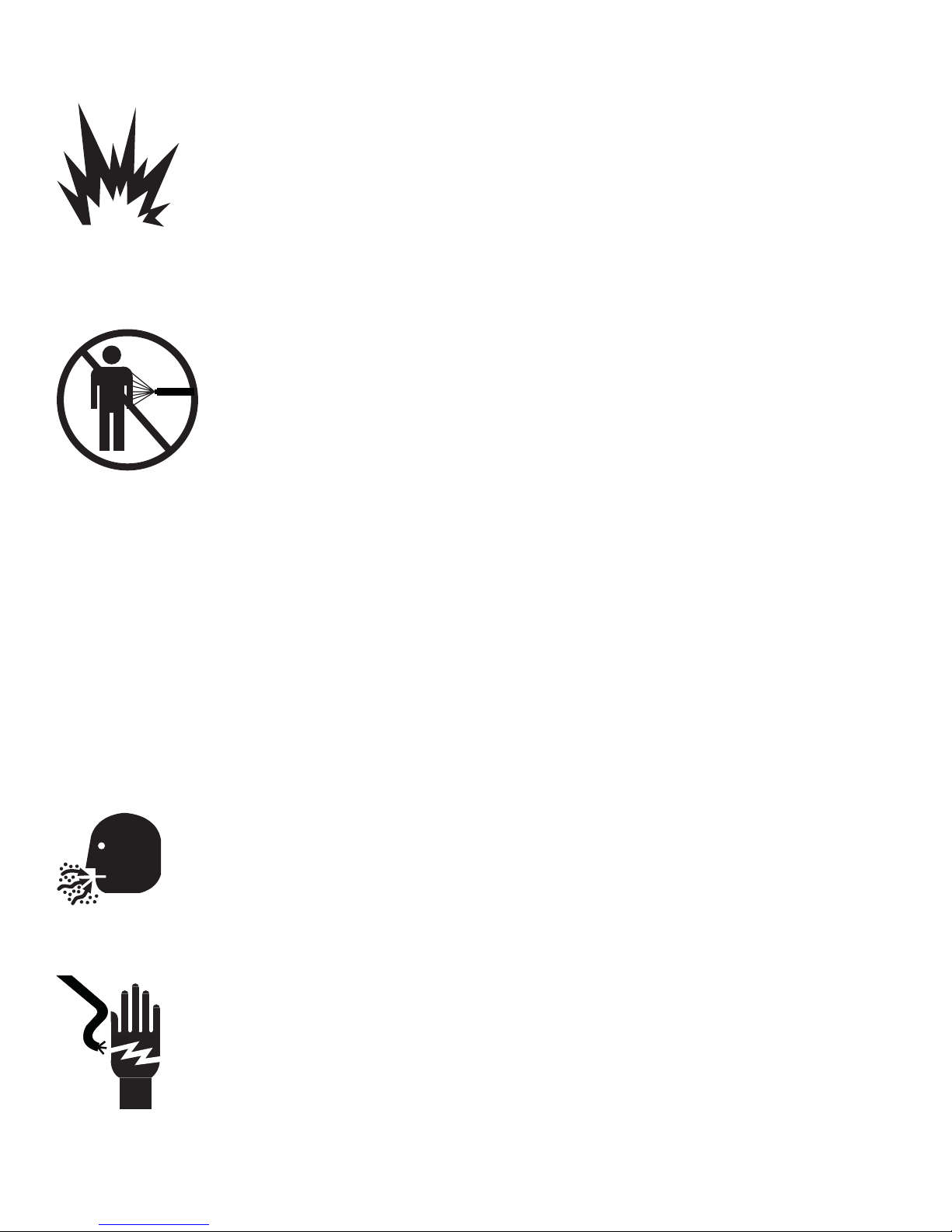
2. Wear proper protective clothing and equipment.
Wear full eye protection (preferably a face shield) while operating this product. The
pressurized spray from this unit can cause severe injury to the eyes. It also may
contain irritants, particles or caustic chemicals.
3. Do not operate with protective covers or guards removed.
Operating this machine with the protective guards or covers removed could
expose high speed moving components which could allow the operator or
bystander to become entangled. Entanglement in this equipment may result in
serious injury, amputation, or death.
This unit may start and stop automatically when switch is in Auto mode.
4. Do not operate with any electrical panels or covers opened.
Operating this unit with any of the electrical panels or covers opened may expose
high powered electrical connections and/or components which may come in contact
with the operator. Contact with high powered electrical equipment by a person could
result in serious injury or death.
5. Do not operate this unit with any of the safety controls bypassed.
This unit was designed with safety in mind. Never allow anyone to bypass, modify, or alter any of the
safety devices on this unit. If any of the safety devices appear to be dysfunctional, do not operate the
unit and immediately contact a qualif ed technician.
Periodically have all the safety devices checked for proper operation.
7
6. Do not operate this unit with any components rated less than the maximum
operating pressure of the unit.
This unit was designed to compress air at a specif c operating pressure and volume.
Never exceed the pressure rating of air tools, spray guns, air operated accessories,
tires, and other inf atables. This can cause them to explode or f y apart and could
result in a serious injury.
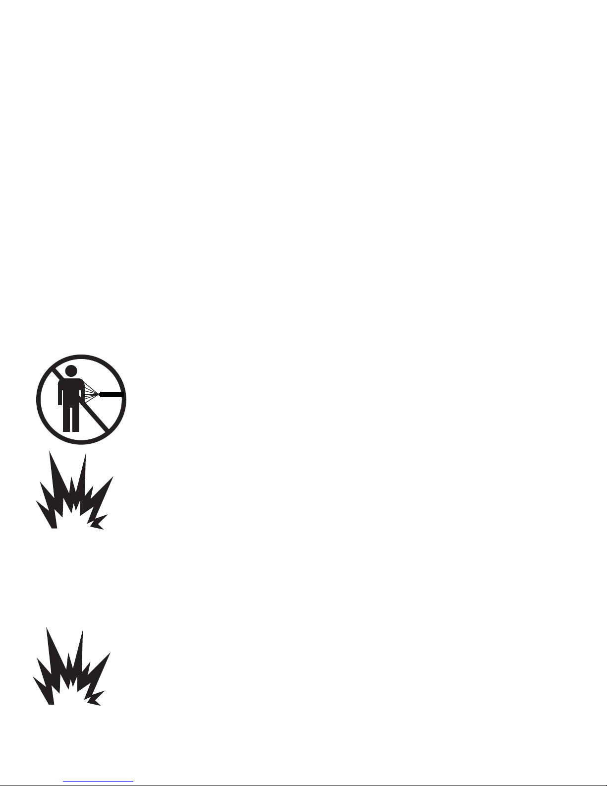
7. Do not direct air stream at people, animals, or any living thing. Use only OHSA
approved air blow guns.
The pressurized spray from this product can cause serious injury or death if
sprayed at people, animals, or any living thing. This machine is capable of
producing extremely high pressures and/or temperatures. The pressurized spray
can cut exposed f esh like a knife. The spray can also cause severe irritation, cuts
and/or burns. It can inject air and/or harmful particles and chemicals into the skin
and other soft tissues, and this can cause serious injury or death. To prevent this
from happening, always hold the air blow gun securely at all times. Never point
spray at people, animals, or any living thing.
Never put hands or f ngers over the spray tip while in operation.
Use only OSHA approved air blow guns.
If an accident occurs and the spray appears to have penetrated the skin, even if the injury
appears to be minor, seek medical care immediately. Do not treat as a simple cut. Be prepared
to tell a physician what particles and/or chemicals you are using.
For treatment instructions, have your physician contact the nearest regional
poison information center for more information.
8. Do not use compressed air from this equipment for breathing.
The compressed air from the compressor is not safe for breathing! The air stream may
contain carbon monoxide, toxic vapors, hydrocarbons, oil mist, water vapor, and/or
solid particles. Never inhale air from the compressor either directly or from a breathing
device connected to the compressor.
9. Unplug or disconnect unit before cleaning or servicing.
To help prevent the risk of injury or death as a result of shock or electrocution or
entanglement while this product is being cleaned, serviced, or repaired, electrical
power must be removed. Unplug or disconnect the power cord or “lock out” the switch
box that supplies power. For more details, please refer to U.S. Department of Labor,
Occupational Safety and Health Administration, Regulation 29 CFR 1910.147, Control
of Hazardous Energy Source (lockout/tagout).
Only qualif ed personnel should attempt any electrical repairs or trouble shooting on the equipment.
Serious injury or death could result from improper repairs and/or trouble shooting.

8
10. Never modify or alter this unit.
For your own safety as well as others, never allow this unit to be altered or modif ed. Modifying or
altering equipment to operate in a fashion other than its original design may cause serious injury or
death.
Never exceed the factory pressure or temperature rating of the system. Be sure that all accessory
equipment and system components meets or exceeds the pressures and temperatures developed by
the unit.
11. Do not operate unit with damaged or worn hoses, f ttings, clamps, or spuds.
Always check the connection hose, control hoses, f ttings, clamps, and spuds
prior to operation. Replace all damaged or worn items with one which meets or
exceeds the specif cations of the original equipment. The use of an improper hose,
f tting, clamp, or spud may cause the hose, f tting, clamp, or spud to rupture which
could result in serious injury or death or damage to the machine.
12. Do not repair damaged hoses or f ttings.
Replace all damaged hoses and/or f ttings with ones which meet or exceed the
specif cations of the original equipment.
Do not use the hose if cuts, leaks, abrasions, bulges, or coupling damage is
evident.
Never remove any hose or f tting while the unit is on. The risk of f uid injection is
present.
13. Do not touch exposed metal such as the compressor pump, motor, tank,
connection hoses, or any f uids.
This unit operates at extremely high temperatures. These temperatures may reach
in excess of 240° F. Touching any exposed metal or other surfaces may cause
severe burns.
Compressor will remain hot for a long period of time. Allow the compressor to cool
to room temperature before attempting any service or repairs.
14. Provide at least three (3) feet of clearance to adjacent construction.
This unit requires adequate ventilation and must be placed in a location which
provides at least three feet of clearance to all adjacent construction. This unit
operates at high temperatures and failure to allow adequate ventilation or restrict the
air f ow may cause the machine to overheat or cause materials in close proximity to
reach their f ash temperatures and ignite.
9
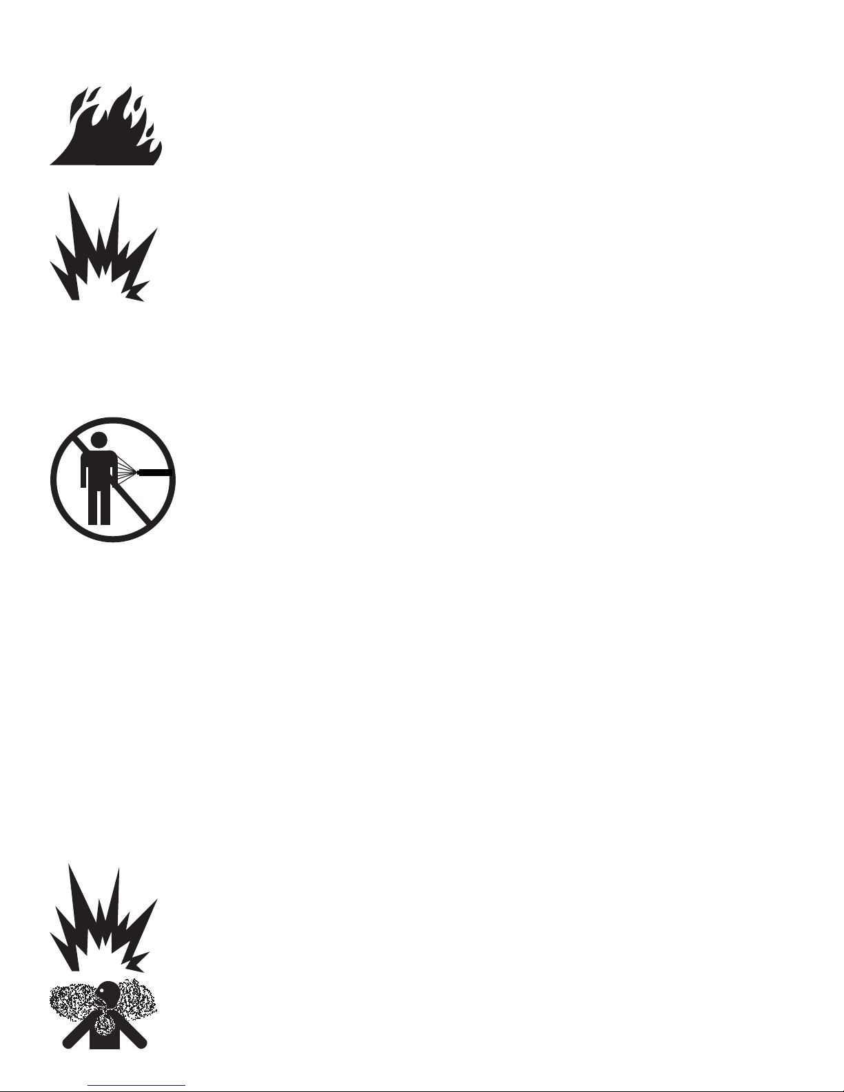
15. Do not operate near f ammable or combustible materials.
This product is not intended for use in locations where f re or explosion hazards may
exist due to the presence of f ammable vapors, liquids or gases, or combustible dusts
or f bers.
Heat generated by the compression cycle and/or drive system is released into
the atmosphere and can cause materials in close proximity to reach their f ash
temperatures and ignite or explode.
Always operate the compressor in a well ventilated area.
Always store f ammable or combustible materials in a secure location away from all
open f ames, sparks, and heat sources.
16. Do not remove any air line or receiver connections before relieving air
pressure in the entire air system and receiver tank(s).
This machine is capable of producing extremely high pressures and/or
temperatures. The pressurized spray can cut exposed f esh like a knife. The
spray can also cause severe irritation, cuts and/or burns. It can inject air and/or
harmful particles and chemicals into the skin and other soft tissues, and this can
result in serious injury or death. To prevent this from happening, always relieve the
air pressure in the entire system and in the receiver tanks before removing any air
lines or receiver connections.
17. Do not operate at pressures, temperatures and rotational speeds in excess of
the manufacturers recommendations.
With safety in mind, the unit was designed and is tested to withstand specif c operating pressures,
temperatures, and volumes. The different components of the machine are matched to produce the
factory set operating pressure and volume. Any modif cation of these settings can cause damage to
the compressor and/or maintenance and operating personnel
Never make adjustments and/or parts substitutions to alter the factory set operating pressures,
temperatures, and volumes.
18. Do not spray f ammable or toxic liquids in conf ned areas. Areas must be well
ventilated. Follow all manufacturers supplied instructions of the material to be
sprayed and the warnings associated with those products.
Never spray f ammable liquids in conf ned areas. The f ammable vapors may
accumulate and then ignite causing an explosion. Always spray f ammable liquids in a
well ventilated area free from combustible materials, gasoline, or solvent vapors.
Never spray toxic liquids or chemicals in conf ned areas. The toxic vapors may
accumulate and overcome the operator. Injury or death may result.
Read and follow all the safety instructions provided on the product label and Material
10
Safety Data Sheet (MSDS) for the material being used.
Use a NIOSH/MSHA approved respirator designed for use each specif c application.
Always wear the appropriate approved safety equipment.
Always operate the compressor in a well ventilated area.
Always store f ammable materials in a secure location away from all open f ames, sparks, and heat
sources.
19. Use this machine only in a well ventilated area.
This unit requires adequate ventilation. Heat generated by the compression cycle of the unit must be
released into the atmosphere. Failure to allow adequate ventilation or restrict the air f ow may cause
the machine to overheat.
20. To prevent corrosion, drain receiver tank(s) after 4 hours of use or at the
end of each day, whichever comes f rst. Have the receiver tank(s) inspected for
corrosion and/or damage periodically.
Always drain receiver tanks daily or after each use. If the receiver or any air lines
develop leaks, immediately replace them. There is a risk of a violent tank or air
line explosion which can cause damage to property and can injure or kill people
nearby.
All pressure vessels should be inspected once every year or more often depending
on use. To f nd your state pressure vessel inspector, look under Division of Labor
and Industries in the government section of a phone book.
Never make modif cations, weld, drill into, or attempt any repairs to compressor tanks.
If modif cations are necessary, take the tank to an A.S.M.E. certif ed coded pressure
vessel shop that can perform these modif cations. The shop will need an ASME “R”
stamp.
Never make adjustments and/or parts substitutions to alter the factory set operating pressures,
temperatures, and volumes.
21. Do not use in f ammable or combustible atmosphere.
This product is not intended for use in locations where f re or explosion hazards may
exist due to the presence of f ammable vapors, liquids or gases, or combustible dusts
or f bers.
It is normal for the electrical contacts within the motor and the electrical control box to
spark. Also, it is normal for gasoline engines to produce extremely high temperatures
and sparks. If the high temperatures or sparks from the compressor come in contact
with f ammable vapors, they may ignite causing a f re or explosion.

11
22. Do not permit untrained personnel to maintain or make repairs on this unit.
Only qualif ed personnel should be permitted to make any type of repairs to this unit. Improper repairs
may cause this unit to malfunction which could result in serious injury or death to the operator, repair
person, or bystander.
23. Risk of Asphyxiation.
The pressurized spray from this unit can cause particles as well as vapors to become
airborne. Keep a safe distance from the vapors and airborne particles. Wear
protective breathing apparatus and approved safety equipment. Use only in a well
ventilated area.
Never use the equipment to spray toxic chemicals. The risk of inhalation or contact
with the skin may result in injury or death.
Never attempt to stop or def ect a leak with any part of your body (including the
use of a rag). The risk of injection is present.
Some dust may contain chemicals known to the state of California to cause cancer, birth defects,
and other reproductive harm. Some of these chemicals are compounds in fertilizers, insecticides,
herbicides, pesticides and arsenic and chromium found in treated lumber.
24. Keep compressor as far away from spraying area as possible. At least 25
feet minimum.
25. Do not leave loose parts, rags, tools, and other foreign matter on the
compressor, drive system, or fan blade.
Loose parts, rags, tools, and other foreign matter can become entangled in the unit or be expelled
from the machine at a high rate of speed. This can result in damage to the machine or serious injury
or death to the operator, repair person, or bystander.
26. All local code requirements for pressure vessels should be investigated to
assure all requirements have been met. Pressure vessels such as the receiver
may require additional ASME code stamping to meet local code(s).
27. Always wear hearing protection when operating or working near the unit.
This unit is capable of producing noise that can be hazardous and can cause hearing
loss. In order to avoid hearing loss, always wear hearing protection when operating or
working near this machine.
28. Do not route hose in a manner that will cause sharp bending, kinking,
cutting, abrasion, or exterior damage.
29. Do not pull on the hose to move the unit, untangle knots, or any other
excessive pulling stress.

12
30. Always release the system pressure prior to service, storage, daily shutdown,
and/or disconnecting the hose or from the unit.
Always release pressure prior to service, storage, daily shutdown, and/or disconnecting the hose
from the unit. Pressure contained within the unit could be released unexpectedly and could cause
injury.
31. Never leave an operating machine unattended.
Always shut off the machine and relieve the system pressure before leaving the unit. Never leave an
operating machine unattended.
32. Never allow children or any unauthorized persons to operate the machine.
Allow only personnel trained in the use of the equipment to operate the unit. Never allow children or
unauthorized personnel to operated the unit. Keep all persons at a safe distance when the machine is
being operated.
33. Never exceed the pressure rating of air tools, spray guns, air operated
accessories, tires and other inf atables could cause them to explode or f y apart.
Exceeding the pressure rating of air tools, spray guns, air operated accessories,
tires and other inf atables could cause them to explode or f y apart. Always follow the
manufacturers recommendations and never exceed the maximum allowable pressure
ratings.
Never use the compressor to inf ate small low pressure objects such as children’s
toys, footballs, basketballs, etc.
34. Explosive fuel. (If gasoline engine equipped)
Gasoline is extremely f ammable and its vapors can explode if ignited. Store gasoline
only in approved containers, in well-ventilated, unoccupied buildings, away from
sparks or f ames.
Do not f ll the fuel tank while the engine is hot or running, since spilled fuel could ignite
if it comes in contact with hot parts or sparks from ignition.
Do not start the engine near spilled fuel; wipe up spills immediately. Never use gasoline as a
cleaning agent.
Do not f ll the fuel tank to the point of over f owing. Allow approximately 1-1/4” of tank space for
expansion.
Shut off fuel valve on engine before transporting unit to prevent fuel leaking from carburetor.

13
35. Do not touch the exhaust system, cylinder head or crankcase when hot. (If
gasoline engine equipped)
The crankcase, cylinder head, exhaust system, and other components can get
extremely hot from operation. To prevent severe burns, do not touch these areas
while the engine is running - or immediately after it is turned off. Never operate the
engine with heat shields or guards removed.
36. Do not inhale engine exhaust gases. (If gasoline engine equipped)
Engine exhaust gases contain poisonous carbon monoxide. Carbon monoxide is
odorless, colorless, and can cause death if inhaled. Avoid inhaling exhaust fumes,
and never run the engine in a closed building or conf ned area without adequate
ventilation.
37. Always shut down the unit and refuel away from open f res or sparks. (If
gasoline engine equipped)
Due to the explosive nature of the fuels involved in running this type of equipment,
never attempt to refuel this unit while it is in operation, or anywhere close to open f res
or sparks. Do not smoke while refueling the unit.
38. Do not over f ll the fuel tank(s). (If gasoline engine equipped)
Do not over f ll the fuel tanks. If any spillage does occur, clean up and/or neutralize the spilled fuel
before any attempt to use the machine is made. It may be prudent to move the machine away from
the area where the fuel was spilled before using the equipment.
39. Disconnect the spark plug lead before cleaning or servicing. (If gasoline
engine equipped)
To help prevent injury while this product is being cleaned, serviced, or repaired, the spark plug lead
must be removed. Ground the lead to prevent sparks that could cause f res.
40. Use only Jenny repair parts and accessories.
To preserve the safety features that are built in to this product, use only Jenny repair parts and
accessories.
This product must be periodically serviced in accordance with the instructions in this owner’s manual.

14
Section 2
Introduction
and
Description

15
INTRODUCTION
This manual contains operation and service instructions for the Jenny Air Compressors.
Brief Compressor Nomenclature:
K15A-8P
Pump Type HorsePower Pressure Tank Tank Letters
F 13 - 1/3 HP Electric A - 125 PSI 2 - 2 Gallon P - Portable
K 12 - 1/2 HP Electric B - 175 PSI 4 - 4 Gallon H - Horizontal
G 34 - 3/4 HP Electric C - 100 PSI 6 - 6 Gallon V - Verticle
GC 1 - 1 HP Electric E - 150 PSI 8 - 8 Gallon HC - Hand Carry
GT 15 - 1-1/2 HP Electric S - 40 PSI 15 - 15 Gallon UM - ASME “UM” Tank
J 2 - 2 HP Electric 17 - 17 Gallon T - Truck Mount
W 3 - 3 HP Electric 30 - 30 Gallon PT - Portable Trailer
U 5 - 5 HP Electric 60 - 60 Gallon SM - Skid Mount
T 75 - 7-1/2 HP Electric 80 - 80 Gallon P2 - 2 Wheel Portable
10 - 10 HP Electric 120 - 120 Gallon C - Climate Control
15 - 15 HP Electric 240 - 240 Gallon S - Sprinkler
20 - 20 HP Electric B - Base Plate DP - Dryer Package
25 - 25 HP Electric
4HG - 4 HP Honda Gas
5HG - 5 HP Honda Gas
6HG - 6 HP Honda Gas
8HG - 8 HP Honda Gas
9HG - 9 HP Honda Gas
11HG - 11 HP Honda Gas
13HG - 13 HP Honda Gas
18HG - 18 HP Honda Gas
Manufactured by Jenny Products, Inc., 850 North Pleasant Avenue, Somerset, PA 15501
GENERAL DESCRIPTION
The Jenny Air Compressor is a reciprocating piston oil bath crankcase air compressor driven
by either an electric motor or gasoline engine mounted either on a base or air compressor receiver.
MAJOR COMPONENTS
The Reciprocating Compressor is comprised of the following major components: the air
compressor pump, air control system, control box, electric motor or gasoline engine and base
weldment or receiver tank.
RECIPROCATING (Piston) AIR COMPRESSOR ASSEMBLY
The air compressor is an oil bath, reciprocating (piston) type. It is powered by an electric motor

16
or gasoline engine V-belt drive sheave assembly. The pumping unit is either a Single Stage or Two
Stage Reciprocating Pump.
SINGLE STAGE AND TWO STAGE RECIPROCATING PUMPS
Reciprocating (Piston) Compressors can be widely found in these two primary conf gurations; Single
Stage and Two Stage.
Single stage air compressors work by drawing free air in and subsequently compressing the air to its
f nal pressure in a single piston stroke. Single stage air compressors can attain pressures of up to 150
PSI. Typically, a single stage pump will have a higher CFM(Cubic Feet per Minute) rating than a two
stage pump because every cylinder is drawing in air and compressing it with air during every rotation.
Two stage air compressors work in a very similar manner with the primary difference being that they
compress the air in 2 steps or stages. During the f rst step or stage, air is drawn in and compressed to
an intermediate pressure. After being compressed in the f rst stage, the air is piped, usually through
an intercooler where the air is allowed to cool, to be compressed in the f nal or second stage. Two
stage compressors are normally good for pressures up to 200psi. Two stage pumps are more eff cient
at higher pressures because the air is cooled between the stages.
ELECTRIC MOTOR
A single or three phase, open drip proof, electric motor, is furnished to drive the air compressor
assembly. Depending on the horsepower rating of the motor and phase, the motor is capable of
operating on different voltages(please see following chart) by changing the wiring in the motor and
starter(if greater than 5HP). These changes should only be attempted by a qualif ed electrician.
Motor HP Rating Voltage Phase
1/3 thru 2 HP 115V, 208V or 230V Single Switchable
3 thru 7-1/2 HP 208V or 230V Single Only
1/3 thru 25 HP 208V Three Only
1/3 thru 25 HP 230V or 460V Three Motor and Starter Switchable-Different Motor Overloads
1/3 thru 25 HP 575V Three Only
GASOLINE ENGINE
A Honda OHV gasoline engine can be furnished to drive the air compressor assembly. The
engines are all industrial/commercial grade and can be either 5.5, 6.5, 8, 11, 13, or 18 HP depending
on the requirements of the air compressor pump.
AIR CONTROL SYSTEM
Constant Run Units - Head Unloader and Discharge Unloader
The air intake is regulated by discharge air pressure demand. A pilot valve is used to operate
an unloading device in the compressor head or a line discharge unloader. For most units, air pressure
is fed through the pilot valve to a specially designed compressor head. The air pressure actuates the
special head’s unloading pins that hold the air intake valves in the closed position. For line discharge
unloaders, a specially designed valve controls the f ow of air. Based on the system pressure, the

17
valve directs the f ow into the air system or to the atmosphere.
Start-Stop Control Units
As with constant run units, the air intake is controlled by air pressure demand. Instead of being
controlled by a pilot valve, Start-Stop units are controllled by an electrical switching device, called a
pressure switch. When the system reaches a designated pressure, or maximum pressure set point,
the pressure switch de-energizes the electric motor. As air is consumed and the system pressure falls
below another designated pressure, or minimum pressure set point, the pressure switch energizes
the electric motor.
Unloading the pressure from the pump for Start-Stop Units is accomplished either by a pressure
switch with unloading capabilities (Single Stage Units) or by a centrif cal unloader(Two Stage Units).
Centrif cal Unloader Units - Centrif cal Unloader units use the rotation of the pump to actuate a
specially designed valve. As the pump rotates, weights spin outward causing a specially designed
valve to close. When the pressure switch de-energizes the electric motor, the pump stops spinning
and consequently allows weights to return to their original position and open the valve. This allows the
trapped air between stage one and two to escape through the valve and bleed to the atmosphere.
Dual Control Units
Dual Control Units allow the compressor to operate in both constant run and start-stop
control. The unit has both a pilot valve and a pressure switch. The unit can be switched from either
operating mode by opening and closing a ball valve. The pilot valve is used to control the compressor
when operating in the constant run and the pressure switch is used to control the compressor when
operating in the stop/start mode.
A good rule of thumb in determining which is the best mode of operation is by the amount of time the
compressor will be required to supply air. If the demand for air is infrequent, then the unit should be
set up for stop/start operation to minimize unnecessary run time and operational wear and tear and to
save energy. If there is a frequent or extended demand for air, and/or the unit is located in a distant or
remote area where access to the compressor is diff cult, the unit should be set up for constant run to
minimize the number of times the motor must start in an hour to ensure good motor life.
PILOT VALVE
The pilot valve is a pressure control device used to maintain system pressure within a preset
range while the compressor runs contantly. The pilot valve may be used to actuate an unloading
device such as a discharge line unloader or an unloading device in the head of the compressor.
When the system reaches a predetermined pressure, the pilot valve actuates the unloading device
and allows the system to run in the unloaded mode. When the system falls below the preset cut-in
pressure, the pilot valve closes and disengages the unloading device(s) which allows the compressor
to pump air into the system.
PRESSURE SWITCH
The pressure switch is a pressure control device. It functions by opening and closing an
electrical switch based on the system pressure. When the system pressure reached a preset
pressure, the pressure switch opens a set of electrical contacts which in turn shuts off the electric

18
motor. Once the air demand drops the system pressure to a predetermined set point, the pressure
switch activates and closes the switch and subsequently starts the electric motor. Many pressure
switches also contain a special unloading device which relieves the pressure from the compressor
pump when the motor is shut off.
PRESSURE REGULATOR
The pressure regulator is used to maintain a constant outlet pressure. It allows adjustment to
any desired pressure below the maximum outlet pressure of the compressor.
BASE/TANK WELDMENT ASSEMBLY
The base/tank weldment serves two primary functions. First, it gives the air compressor a
rigid structure that was designed specif cally for the operational requirements of the unit. Secondly,
the weldment provides the mounting capability for all of the major components of the compressor
assembly.
MAGNETIC STARTER
A magnetic starter is included on all models 5HP and larger on simplex and all duplex single
phase units and three phase units. The magnetic starter works in conjunction with a pressure switch
to start and stop the electric motor. The magnetic starter is primarily a switch which can take the full
load of starting and stopping an electric motor when other switching devices are incapable of handling
this load. Starters typically are made of two components; the contractor and a heater overload block.
The contractor is a switch designed to engage and disengage all the power to an electric
motor.
The heater overload block is a protective device for the motor. If the motor draws over a preset
number of amps, the overload will disengage the starter and shut the unit down.
CHECK VALVE (Start-Stop Units and All 2-Stage Units)
The check valve functions by allowing air to only move in one direction. This is required and
accomplished when the unit switches into either unload (Constant Run Unit) or stopped (Start-
Stop Unit) mode of operation. In this situation, the air receiver pressure is built up to the maximum
pressure. The pilot valve or pressure switch senses the pressure and at this point either closes the air
intake valves or turns off the motor.
RELIEF VALVE
A pressure relief valve is mounted on the manifold assembly or on the receiver. In the event
that air pressure continues to build when the demand for compressed air has either slowed or ceased
altogether, the relief valve will open at a predetermined set point and allow excess pressure to
discharge into the atmosphere. In most cases, this is an indication that there has been a failure in air
system somewhere and the cause should be investigated immediately.
AIR INTAKE FILTER(S)
Air f lters are designed to remove foreign particles from the air entering the pump. Keeping the f lters
clean and free from obstructions will ensure the pump continually receives a clean air supply.

19
Section 3
Preparation
for Use
and
Initial
Installation
Instructions

20
PREPARATION FOR USE
GENERAL
The Jenny Air Compressor unit was thoroughly tested at our factory as part of the
manufacturing process. The machine will function as designed if properly assembled, set up, and
operated. There are certain steps that must be taken prior to attempting to operate unit to assure it is
ready for operation.
INSPECTION OF NEW EQUIPMENT
1.) Check the box or crate for possible shipping damage.
If extensive damage is apparent to the box, please notify the freight carrier immediately. Do not open
the box. Wait for the freight carrier’s inspector to be present before opening.
2.) Open the shipping box and inspect for damage and missing components.
You should f nd:
1 - Jenny Air Compressor
1 - Instruction Manual and Warranty Card(s)
1 - Spare parts bag (not included with all units)
Check all of the equipment against the packing list. Examine identif cation plates for positive
identif cation of the equipment received. If any of these components are missing, please notify the
distributor from whom the machine was purchased immediately.
Inspect the unit carefully for any possible hidden damage. If the unit or any of the components are
damaged, please notify the freight carrier immediately.
Do not attempt to repair or use the unit or any of the components
if the unit is damaged. Notify the distributor from whom the
machine was purchased immediately.
3.) Record the machine model number, serial number, and specif cations located on the
machine. Always include unit model, unit serial number, and compressor model number when
ordering spare parts.
4.) Fill out the enclosed warranty card.
5.) Inspect for and tighten any loose nuts and/or bolts.
6.) Inspect the controls, instruments, and gauges for damage or loose mountings.
7.) Inspect all hoses for kinks and loose connections.
8.) Inspect electrical wiring for cuts, fraying, and loose connections.
!WARNING
Table of contents
Popular Air Compressor manuals by other brands


Ingersoll-Rand
Ingersoll-Rand 7/26E Operation & maintenance manual

Central Hydraulics
Central Hydraulics 65549 Instructions and precautions

Craftsman
Craftsman 919.167621 owner's manual

Master
Master 102D owner's manual

Allmand
Allmand Maxi-Air MA400 Operator's manual

Bitzer
Bitzer OSK/N7441-EX operating instructions