Jensen MSR2007 User manual

MSR2007
Installation and Operation Manual
MARINE AUDIO SYSTEM
Manual del Usuario/Guide d'Utilisateur
SAT
AUDIO
INFO

MSR2007
2
CONTENTS
Safety Information .............................................................................................. 1
Installation........................................................................................................... 2
Wiring................................................................................................................... 4
Basic Operation .................................................................................................. 5
Tuner Operation.................................................................................................. 7
Sirius Radio Operation....................................................................................... 8
iPod Operation.................................................................................................... 9
Care and Maintenance...................................................................................... 10
Troubleshooting................................................................................................ 10
Specifications ...................................................................................................10
CONTENIDO
Información de Seguridad................................................................................ 11
Instalación......................................................................................................... 12
Cableado............................................................................................................ 14
Operación Básica ............................................................................................. 15
Operación del Sintonizador............................................................................. 17
Operación de Radio Sirius............................................................................... 18
Operación del iPod........................................................................................... 19
Cuidado y Mantenimiento................................................................................ 20
Solución de Problemas.................................................................................... 20
Especificaciones ...............................................................................................20
TABLE DES MATIÈRES
Informations sur la securite............................................................................. 21
Installation......................................................................................................... 22
Câblage.............................................................................................................. 24
Operation de Base............................................................................................ 25
Operation tuner................................................................................................. 27
Operation radio Sirius...................................................................................... 28
Operation iPod.................................................................................................. 29
Soin et entretien................................................................................................ 30
Dépannage ........................................................................................................ 30
Specifications ...................................................................................................30

MSR2007
1
SAFETY INFORMATION
When Boating
Keep the volume level Iow enough to be aware of your surroundings.
Protect from Water
Do not submerge or expose the product directly to water, as this can cause electrical shorts,
fire or other damage.
Protect from High Temperatures
Exposure to direct sunlight for an extended period of time can produce very high temperatures
inside your vessel. Give the interior a chance to cool down before starting playback.
Do not mount radio within close proximity of engine compartment.
Use the Proper Power Supply
This product is designed to operate with a 12 volt DC negative ground battery system.
WARNING:
• DO NOT OPEN, DISASSEMBLE OR ALTER THE UNIT IN ANY WAY. Doing so may
result in fire, electric shock or product damage.
• USE THE CORRECT AMPERE RATING WHEN REPLACING FUSE. Failure to do so
may result in fire, electric shock or product damage.
• DO NOT INSTALL IN LOCATIONS THAT MIGHT HINDER VEHICLE OPERATION. Doing
so may obstruct vision or hamper movement which can result in a serious accident.
• INSTALL THE WIRING SO THAT IT IS NOT CRIMPED OR PINCHED BY SCREWS OR
SHARP METAL EDGES. Route the cables away from moving parts or sharp pointed
edges. This will prevent crimping and damage to the wiring. If the wiring must pass
through a metal hole, be sure to use a rubber grommet to prevent the wire's insulation
from being cut by the metal edge of the hole. It is also recommended to apply sealing
caulk to any opening that may potentially allow water to enter.
• Be sure to choose a location that is flat and has clearance above the unit to prevent any
damage, as well as allow for ventilation.
• Before drilling any holes, carefully inspect the area underneath and behind the mounting
surface where the devices will be mounted to make sure it will not interfere with existing
wires, fuel lines, the fuel tank or any other objects that could be damaged.
• Always disconnect the vehicle negative battery terminal to prevent accidental shorting
during installation.

MSR2007
2
INSTALLATION
Before You Begin
Before you begin, always disconnect the battery negative terminal.
Important Notes
• Before final installation, test the wiring connections to make sure the unit is connected
properly and the system works.
• Use only the parts included with the unit to ensure proper installation. The use of
unauthorized parts can cause malfunctions.
• Consult with your nearest dealer if installation requires the drilling of holes or other
modifications to your vessel.
• Install the unit where it does not interfere with driving and cannot injure passengers if
there is a sudden or emergency stop.
• Avoid installing the unit where it will be subject to high temperatures from direct sunlight,
hot air, or from a heater, or where it would be subject to excessive dust, dirt or vibration.
Wired Commander Mounting
1. Choose a mounting area for the wired commander that is clean and flat, allowing the rear
gasket to fully seal to the mounting surface.
2. Secure the wired commander using either of the recommended mounting methods
detailed in the diagrams below.
7/8” HOLE REQUIRED
FOR CABLE
M4 MOUNTING SCREWS (4-PCS)
MINIMUM SCREW LENGTH 1 1/2”
7/8” HOLE REQUIRED FOR CABL
E
M5X8 SCREWS REQUIRED FOR MOUNTING
MAXIMUM SCREW DEPTH IN COMMANDER 1/4”

MSR2007
3
Tuner/Amplifier Mounting
1. Choose a mounting area for the tuner/amp module that will provide plenty of ventilation to
prevent the amplifier from overheating. The tuner/amp module can be mounted in the hor-
izontal or vertical position. Please note that when mounting in vertical position, do not
mount with the harness exit points facing straight up, as water can collect around the
chassis in these areas.
2. Attach the 4 rubber mounting feet, provided, to the bottom of the tuner/amp metal plate.
This will provide clearance from surface moisture and promote good ventilation for the
heat sink.
3. Using the shortest length of the recommended size screws possible, mount the tuner/
amplifier as detailed in the diagram on the right.
4. Route the tuner/ amplifier harness and cable throughout the vessel as required. Keep
some slack in the harness/ cables so it won't be too tight, as this can cause damage to the
wires.
5. Follow the wiring diagram carefully and make certain all connections are secure and
insulated with crimp connectors or electrical tape to ensure proper operation.
6. After completing the wiring connections, reconnect the negative terminal on the battery
and turn the unit on to confirm operation (vessel accessory switch must be on). If the unit
does not operate, disconnect battery, recheck all wiring and refer to the trouble-shooting
guide located in the back of the manual.
Reconnect Battery
When wiring is complete, reconnect the battery negative terminal.
STAINLESS STEEL M4 SCREWS REQUIRED
WITH MINIMUM LENGTH OF 1”
1 1/2” PILOT HOLES FOR SUPPLIED SELF-STARTING SCREWS
180 PILOT HOLES WHEN USING THREADED MACHINE SCREWS
1 3/4” HOLE REQUIRED FOR
CABLE/CONNECTOR
REMOVABLE RUBBER FEET
4 PLACES

MSR2007
4
WIRING

MSR2007
5
BASIC OPERATION
Power On/Off
Press any button on the front panel to turn the unit on. Press the POWER button (1) to turn the
unit off. The unit will resume the last mode (Tuner, Aux, etc.). The POWER button is illuminated
whenever the +12V DC Switched (red wire) is powered, regardless of whether the unit is on or
off.
Volume Control
To increase the volume, press the VOLUME + button (2a). To decrease the volume, press the
VOLUME - button (2b). The maximum volume level is “46”.
Mute
Press the MUTE button (17) on the control panel to mute the audio output. Press MUTE again
to restore the audio output to the previous level.
Mode
Press the MODE button (4) on the control panel to select a different mode of operation, as
indicated on the display panel. Available modes include Tuner, SIRIUS, iPod and AUX In.
NOTE: iPod and SIRIUS mode will be skipped if the module is not installed.
Reset
The reset button should be activated for the following reasons:
• initial installation of the unit when all wiring is completed
• function buttons do not operate
• error symbol on the display
Use a ball point pin or thin metal object to press the RESET button, located on the tuner box.
You can recover factory default settings using the RESUME function located on the system
menu. With “YES” flashing, press the MODE button (4) to activate.
Audio Menu
Press the AUDIO button (3) on the control panel to access the audio menu. You can navigate
through the audio menu items by pressing the AUDIO button repeatedly. Once the desired
menu item appears on the display, adjust that option by pressing the VOLUME +/- buttons (2)
within 5 seconds. The unit will automatically exit the audio menu after five seconds of inactivity.
The following menu items can be adjusted.
Bass Level
Use the VOLUME buttons to adjust the Bass level range from “-6” to “+6”.
Treble Level
Use the VOLUME buttons to adjust the Treble level range from “-6” to “+6”.
Balance
Use the VOLUME buttons to adjust the Balance between the left and right speakers from “L12”
(full left) to “R12” (full right).
Fader
Use the VOLUME buttons to adjust the Fader between the rear and front speakers from “R12”
(full rear) to “F12” (full front).
3
2a
411
12
13 14
15
16
17
1
2b
SAT
AUDIO
INFO
18
19
5
6 7
8910
20

MSR2007
6
System Menu
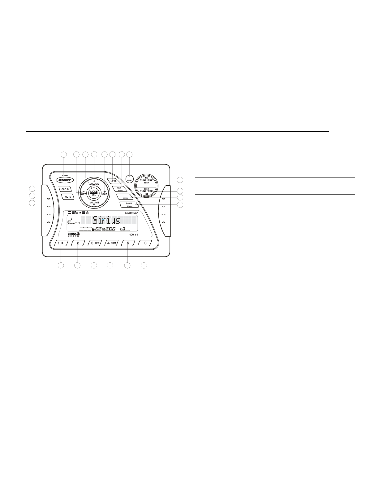
1. Press and hold the AUDIO button (3) for more than 3 seconds to enter the system menu.
“MENU” will appear on the display, followed by the first menu item, “CONTRAST.”
2. Press the TUNE/TRK >>| or |<< button (19, 18) or press the AUDIO button repeatedly to
navigate the system menu and select the desired item.
3. Press the VOLUME +/- buttons (2) to adjust the selected menu item.
4. Press the AS/PS button to return to the previous operation immediately or wait for 5
seconds to return automatically.
The following items can be adjusted:
• CONTRAST (0 – 10): Set LCD contrast.
• LOW BATT (ON/OFF): Monitor voltage on ACC line.
• AREA (USA/LATIN/EUROPE): Set frequency spacing for various regions.
• VOL PGM (0 – 46): Select an automatic turn-on volume.
• BEEP TONE (ON/OFF): Turn the audible beep ON/OFF (heard when functions/buttons
are selected). NOTE: Beep tone off will not affect LOW BATT audible tone .
• RESUME: Return the EEPROM to factory default set up values and reset the Sirius Tuner
Settings. "Yes" will blink on the LCD to confirm. Press MODE to select.
LOW BATTERY Operation
If LOW BATT is set to “ON”, a alarm will s ound (8 beeps every 30 sec) when the voltage drops
to 10.8V (+/- 0.03V). A visual warning (LOBA) will appear flashing (8 fl ashes every 30 sec) in
the lower left corner of the LCD display.
NOTE: “OFF” is the default setting for LOW BATT. If the audio is muted or the volume is
set to 0, the audible beep will not be heard.
Equalizer
Press the EQ button (11) to turn on the equalization function and select between five pre-
defined bass and treble curves: OFF > POP > JAZZ > CLASSIC > BEAT > ROCK.
iX-Bass
Press and hold the EQ/IX-BASS button (11) toggle loudness on/off. When listening to music at
low volumes, this feature will boost the bass range to compensate for the characteristics of
human hearing.
Auxiliary Input
To access an auxiliary device:
1. Connect the portable audio player to the AUX IN cables on the back of the tuner box.
2. Press the MODE button (4) to select Aux In mode.
3. Press MODE again to cancel Aux In mode and go to the next mode.
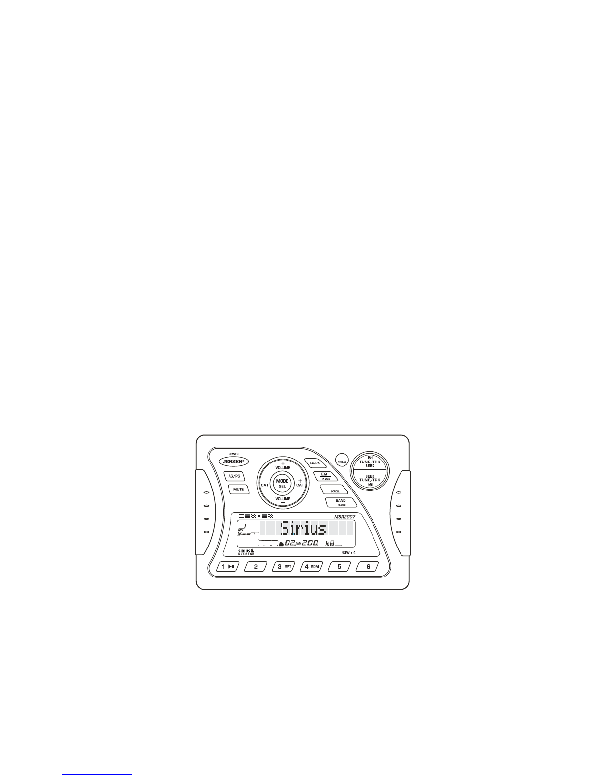
Liquid Crystal Display (LCD)
The current frequency and activated functions are shown on the LCD panel (23).
NOTE: LCD panels may take longer to respond when subjected to cold temperatures for
an extended period of time. In addition, the visibility of the numbers on the LCD may
decrease slightly. The LCD display will return to normal when the temperature increases
to a normal range.
Scroll
When the information is too long to be displayed on the LCD, press and hold the INFO/
SCROLL button (12) to view the entire title. The information will scroll twice and then return to
abbreviated text.
Quick Exit Hot Key
In the following modes and conditions, press the AS/PS button < 3 seconds to quickly exit the
current operation without waiting for the system default time out:
• System menu operation
• Searching mode
• Audio menu operation
• LOCAL: this model favors access to local stations whose signals are much stronger;
thereby improving radio reception.
• DISTANT: this is terminate the local receive mode to normal receive mode.

MSR2007
7
TUNER OPERATION
Select a Band
Press the BAND button (16) to change between three FM bands and two AM (MW) bands.
Manual Tuning
Press the TUNE/TRK >>| or |<< buttons (18, 19) to seek stations up/down step by step.
Auto Seek Tuning
Press and hold the TUNE/TRK >>| or |<< buttons (18, 19) to automatically seek the next or
previous strong station.
Preset Stations
Six numbered preset buttons store and recall stations for each band.
Store a Station
Select a band (if needed), then select a station. Press and hold a preset button (5-10) for two
seconds. The preset number will appear in the display.
Recall a Station
Select a band (if needed). Press a preset button (5-10) to select the corresponding stored
station.
Automatically Store / Preset Scan (AS/PS)
Automatically Store
Select a band (if needed). Press and hold the AS/PS (15) button for more than three seconds
to automatically select six strong stations and store them in the current band. The new stations
replace any stations already stored in that band.
NOTE: During Auto Store (AS), the tuner will default to “Local” mode while scanning the
band initially. After scanning the entire band once, the unit will switch to “Distant” mode
for all subsequent Auto Store tuning.
Preset Scan
Select a band (if needed). Press AS/PS (15) to scan stations stored in the current band. The
unit will pause for ten seconds at each preset station. Press AS/PS again to stop scanning
when the desired station is reached.
Local/Distant Reception (LO/DX)
During radio operation, received signals are usually in stereo mode as indicated by the “ST”
icon. However, when the signals are weak or intermittent, you can activate the Local (LOC)
mode by pressing the LO/DX button (20). This mode favors access to local stations whose
signals are much stronger; thereby improving radio reception. Press the LO/DX button again to
terminate Local receive mode.
3
2a
411
12
13 14
15
16
17
1
2b
SAT
AUDIO
INFO
18
19
5
6 7
8910
20

MSR2007
8
SIRIUS RADIO OPERATION
Switching to SIRIUS Mode (Requires Optional Sirius Tuner)
Press the MODE button (4) to change the mode to Sirius radio mode.
Accessing your SIRIUS ID
1. In Sirius mode, press and hold the BAND/SEARCH button (16) to select DIRECT mode.
2. Press the MODE button (4) to activate Direct mode.
3. Press the MODE button for each digit to enter “000”.
4. Press MODE again to confirm. This will display the Sirius ID number for your tuner.
5. The Sirius ID number will scroll twice and then freeze with the first 11 digits on the display.
Press the INFO/SCROLL button (12) to display the remaining digit.
Selecting a Band
In Sirius mode, press the BAND button (16) to access the Sirius user-preset channel groups in
the following order: SR-1, SR-2, SR-3.
Category Tuning
1. Press the CAT - /+ buttons (13/14) to change the category. Each category title and song
title will be displayed in increments.
2. While in the category mode, press the CAT - /+ buttons again to view category names.
(The lowest channel number within the chosen category will always be the default first
channel tuned.)
3. Press the MODE button (4) or the TUNE/TRK |<< / >>| buttons (18/19) to choose desired
channels in that category.
4. Press the TUNE/TRK buttons to select a channel within the chosen category.
5. Press MODE to confirm channel selection.
Channel Up/Down Tuning
Press the TUNE/TRK |<< / >>| buttons (18/19) to search for a channel. Press and hold the
TUNE/TRK buttons to fast search.
Storing Preset Channels
The preset buttons (5-10) can be used to store 6 channels, allowing convenient access to your
favorite channels.
Programming Channels
1. Select the channel you want to store in memory.
2. Press and hold a preset button (5-10) until the corresponding preset button number
appears.
3. Repeat steps 1 and 2 to program additional channels.
Quick Tuning
Press one of the six preset buttons (5-10) to select a preset channel directly.
Channel Direct Access Searching
1. Press and hold the BAND/SEARCH button (16) to access Direct Tune mode. “DIRECT-T”
appears on the display for a few seconds.
2. Press the MODE button (4) to confirm.
3. Press the TUNE/TRK |<< / >>| buttons (18/19) to move between the three digits.
4. Use the VOLUME +/- buttons (2) to select a number for each position.
5. Press the MODE button to confirm each digit.
6. Press the MODE button again to tune to the selected file.
Alternate Display Information
Press INFO/SCROLL button (12) to change the display information in the following order:
ARTIST NAME > SONG TITLE > CATEGORY > CHANNEL NAME.
Satellite Signal Strength
The display will indicate satellite reception strength as shown below.
Signal Strength Strength Display
No Signal
Weak
Good
Excellent
3
2a
411
12
13 14
15
16
17
1
2b
SAT
AUDIO
INFO
18
19
5
6 7
8910
20

MSR2007
9
IPOD OPERATION
This unit is equipped with an iPod ready function that will allow you to control your iPod (if
compatible) using the control panel control buttons. The following iPod versions are supported:
• iPod 3G (firmware version 2.2 only)
• iPod Mini
• iPod 4G
• iPod Photo
• iPod Nano
• iPod 5G (Video)
NOTE: iPod and iPod Cable sold separately.
Accessing iPod Mode
The unit will automatically switch to iPod mode
when an iPod is plugged into the iPod cable.
To return to the iPod menu from any other source,
press the MODE button (4) on the control panel or
remote control until “iPod” appears on the display.
Turning the iPod On/Off
The iPod power turns on automatically when an
iPod is connected to 30-pin iPod cable, as long as
the vehicle ignition is turned on. You can turn the
iPod off by disconnecting it from the cable or by
turning the ignition off. When the ignition is turned
off, the iPod will pause and then enter sleep mode after 2 minutes. While the iPod is
connected, the power cannot be turned on or off from the iPod itself.
NOTE: The iPod will continuously recharge when connected to the unit, as long as the
vehicle ignition is turned on.
Controlling Playback
Pausing Playback
During playback, press the 1/>|| button (8) to pause the iPod player. “Pause” will appear on the
LCD. Press 1/>|| again to resume playback.
Repeat Play
During playback, press the 3/RPT button (5) to repeat the current song. “Repeat” will appear
on the LCD. Press 3/RPT again to stop repeat playback.
Random Play
During playback, press the 4/RDM button (7) to play all songs in the current category in
random order. Random play will begin once the current song has finished playing. “Shuffle” will
appear on the LCD. Press 4/RDM again to stop random playback.
Selecting Tracks
During playback, press the TUNE/TRK |<< / >>| button (18/19) to play the previous or next
track in the current category. Press the TUNE/TRK |<< button (18) once to play the song from
the start position or press TUNE/TRK |<< twice to play the previous track.
Press and hold the TUNE/TRK |<< / >>| button (18/19) to fast reverse/forward the song.
NOTE: If you press and hold the TUNE/TRK |<< / >>| button to change the current song
to the previous/next song, you will exit fast reverse/forward mode.
Alternate Display Information
Press INFO/SCROLL button (12) to change the display information in the following order:
ARTIST NAME > SONG TITLE > FOLDER NAME.
Search Mode
Press and hold the BAND/SEARCH button (16) to enter iPod search mode. Press BAND/
SEARCH again to access Playlist, Artist, Album, Genre, Song, or Composer (consecutively).
When search mode is selected, press the MODE button (4) to confirm selection. Use the
VOLUME +/- buttons (2) to navigate through various list selections. Press MODE (4) to make
your final selection.
iPod CABLE
iPod
photo iPod iPod
mini iPod
nano
iPod
Video
MA IRNE
3
2a
411
12
13 14
15
16
17
1
2b
SAT
AUDIO
INFO
18
19
5
6 7
8910
20

MSR2007
10
CARE AND MAINTENANCE
• Keep the product dry. If it does get wet, wipe it dry immediately. Liquids might contain
minerals that can corrode the electronic circuits.
• Keep the product away from dust and dirt, which can cause premature wear of parts.
• Handle the product gently and carefully. Dropping it can damage circuit boards and
cases, and can cause the product to work improperly.
• Wipe the product with a dampened cloth occasionally to keep it looking new. Do not use
harsh chemicals, cleaning solvents, or strong detergents to clean the product.
• Use and store the product only in normal temperature environments. High temperature
can shorten the life of electronic devices, damage batteries, and distort or melt plastic
parts.
Ignition
The most common source of noise in reception is the ignition system. This is a result of the
radio being placed close to the ignition system (engine). This type of noise can be easily
detected because it will vary in intensity of pitch with the speed of the engine.
Usually, the ignition noise can be suppressed considerably by using a radio suppression type
high voltage ignition wire and suppressor resistor in the ignition system. (Most vessels employ
this wire and resistor but it may be necessary to check them for correct operation.) Another
method of suppression is the use of additional noise suppressors. These can be obtained from
most CB/A radio or electronic supply shops.
Interference
Radio reception in a moving environment is very different from reception in a stationary
environment (home). It is very important to understand the difference.
AM reception will deteriorate when passing under a bridge or when passing under high voltage
lines. Although AM is subject to environmental noise, it has the ability to received at great
distance. This is because broadcasting signals follow the curvature of the earth and are
reflected back by the upper atmosphere.
TROUBLESHOOTING
SPECIFICATIONS
FM Radio
Frequency Coverage (USA) . . . . . . . . . . . . . . . . . . . . . . . . . . . . . . . . . . . 87.5 to 107.9 MHz
Frequency Coverage (Europe) . . . . . . . . . . . . . . . . . . . . . . . . . . . . . . . . . . 87.5 to 108 MHz
Sensitivity (S/N=30dB) . . . . . . . . . . . . . . . . . . . . . . . . . . . . . . . . . . . . . . . . . . . . . . . . . . 4µV
Image Rejection . . . . . . . . . . . . . . . . . . . . . . . . . . . . . . . . . . . . . . . . . . . . . . . . . . . . . >45 dB
Stereo Separation . . . . . . . . . . . . . . . . . . . . . . . . . . . . . . . . . . . . . . . . . . . . . . . . . . . . >25 dB
AM/MW
Frequency Range (USA). . . . . . . . . . . . . . . . . . . . . . . . . . . . . . . . . . . . . . . . . 530-1720 kHz
Frequency Range (Europe). . . . . . . . . . . . . . . . . . . . . . . . . . . . . . . . . . . . . . . 522-1620 kHz
Sensitivity (S/N=20dB) . . . . . . . . . . . . . . . . . . . . . . . . . . . . . . . . . . . . . . . . . . . . . . . . 36 dB
General
Operating Voltage . . . . . . . . . . . . . . . . . . . . . . . . . . . . . . . . . . . . . . . . . . . . . . . . DC 12 Volts
Grounding System. . . . . . . . . . . . . . . . . . . . . . . . . . . . . . . . . . . . . . . . . . . . Negative Ground
Speaker Impedance . . . . . . . . . . . . . . . . . . . . . . . . . . . . . . . . . . . . . . 4-8 ohms per channel
Tone Controls:
Bass (at 100 Hz). . . . . . . . . . . . . . . . . . . . . . . . . . . . . . . . . . . . . . . . . . . . . . . . . . :±10dB
Treble (at 10 kHz). . . . . . . . . . . . . . . . . . . . . . . . . . . . . . . . . . . . . . . . . . . . . . . . . : ±10dB
Power Output . . . . . . . . . . . . . . . . . . . . . . . . . . . . . . . . . . . . . . . . . . . . . . . . . . . . . . 40W x 4
Current Drain. . . . . . . . . . . . . . . . . . . . . . . . . . . . . . . . . . . . . . . . . . . . . . . .15 Ampere (max.)
Commander Dimensions. . . . . . . . . . . . . . . . . . . . . . . . . . . . . .5.15” (W) x 1.2” (D) x 3.7” (H)
Tuner/Amp Dimensions. . . . . . . . . . . . . . . . . . . . . . . . . . . . . .8.35” (W) x 6.55” (D) x 2.4” (H)
Symptom Cause Solution
No power The vessel’s accessory
switch is not on If the power supply is properly
connected to the vessel’s acces-
sory terminal, switch the ignition
key to “ACC”
The fuse is blown Replace the fuse
No sound Volume is too low Adjust volume to audible level
Wiring is not properly con-
nected Check wiring connections
The operation keys do
not work The built-in microcomputer
is not operating properly
due to noise
Press the RESET button
Cannot tune to radio sta-
tion, auto-seek does not
work
The antenna cable is not
connected Insert the antenna cable firmly
The signals are too weak Select a station manually

MSR2007
11
INFORMACIÓN DE SEGURIDAD
Cuando Navegue
Mantenga el volumen lo suficientemente bajo para escuchar a su alrededor.
Protéjalo del Agua
No sumerja o exponga el producto directamente al agua, pues puede causar cortos eléctricos,
incendios o daños.
Protéjalo contra las Altas Temperaturas
Exposición a luz solar directa por un periodo extendido de tiempo puede producir muy altas
temperaturas dentro de su buque. Deje que el interior se enfríe antes de iniciar la
reproducción.
No monte un radio en las proximidades del compartimiento del motor.
Utilice la Alimentación de Energía Adecuada
Este producto está diseñado para operar con un sistema de baterías de 12voltios de Corriente
Continua negativa conectado a tierra.
ADVERTENCIA:
• NO ABRA, DESARME O ALTERE LA UNIDAD DE NINGUNA FORMA. Hacerlo puede
provocar fuego, choque eléctrico o daños.
• USE EL AMPERAJE CORRECTO CUANDO REEMPLACE UN FUSIBLE. No hacerlo
puede provocar fuego, choque eléctrico o daños.
• NO INSTALE EN LUGARES QUE PUEDAN OBSTRUIR LA OPERACIÓN DEL
VEHÍCULO. Hacerlo puede obstruir la visión u obstaculizar movimientos y puede
provocar accidentes serios.
• INSTALE EL CABLEADO DE TAL FORMA QUE NO SE DOBLE O PUNCE CON
TORNILLOS O FILOS. Coloque los cables lejos de partes movibles o con bordes filosos
o con punta. Esto prevendrá doblar o dañar el cableado. Si el cableado debe pasar por
un agujero de metal, asegúrese de usar un reborde de goma para prevenir que se corte
el cable con el borde metálico del agujero. También se recomienda aplicar sellador en
cualquier apertura que potencialmente pueda permitir el ingreso de agua.
• Asegúrese de elegir una ubicación que sea plana y tenga lugar arriba de la unidad para
prevenir cualquier daño, como así también permitir la ventilación.
• Antes de realizar algún agujero, cuidadosamente inspeccione el área debajo y detrás de
la superficie de montaje donde los dispositivos se fijarán, para asegurarse que no
interferirán con cables, tubos o tanques combustibles o cualquier otro objeto que pueda
ser dañado.
• Siempre desconecte el terminal negativo de la batería del vehículo para prevenir cortos
accidentales durante la instalación.

MSR2007
12
INSTALACIÓN
Antes de Empezar
Antes de empezar, siempre desconecte la terminal negativa de la batería.
Notas Importantes
• Antes de la instalación final, pruebe las conexiones de cables para asegurarse de que la
unidad esté conectada adecuadamente y el sistema funcione.
• Utilice solamente las partes incluidas con la unidad para asegurarse la instalación
adecuada. El uso de partes no autorizadas puede causar mal funcionamiento.
• Consulte su revendedor más cercano si la instalación requiere taladrar agujeros u otras
modificaciones a su buque.
• Instale la unidad donde no interfiera con el manejo y no pueda herir a ningún pasajero si
se frena repentinamente o de emergencia.
• Evite instalar la unidad donde sea sometida a altas temperaturas debido a luz directa del
sol, aire caliente o del calentador, o donde reciba polvo, suciedad o vibración en exceso.
Montaje del Comando Cableado
1. Elija un área de montaje para el comando cableado que sea limpio y plano, permitiendo
que la junta trasera se selle completamente contra la superficie de montaje.
2. Asegure el comando cableado usando uno de los métodos de montaje recomendados en
detalle en los diagramas de abajo.
TORNILLOS DE MONTAJE M4 (4 PIEZAS)
LARGO DE TRONILLO MÍNIMO DE 1½”
AGUJERO DE 7/8" REQUERIDO
TORNILLOS M5X8 REQUERIDOS PARA MONTAJE
PROFUNDIDAD DE TORNILLO MÁXIMA EN COMANDO DE ¼”
PARA CABLE
AGUJERO DE 7/8" REQUERIDO
PARA CABLE

MSR2007
13
Montaje de Radio/Amplificador
1. Elija un área de montaje para el módulo de radio/amplificador que provea mucha venti-
lación para prevenir que el amplificador se recaliente. El módulo de radio/amplificador
puede ser montado en posición horizontal o vertical. Por favor, note que cuando monte
en posición vertical, no realice el montaje con los puntos de salida del arnés hacia arriba
pues se puede juntar agua alrededor del chasis en éstas áreas.
2. Fije los 4 pies de montaje de goma provistos, a la parte baja del plato de metal del radio /
amplificador. Esto brindará espacio de la humedad de la superficie y promueve buena
ventilación al lavabo del calefactor.
3. Usando los tornillos recomendados más cortos posibles, monte el radio / amplificador
como se detalla en el diagrama a la derecha.
4. Coloque el arnés y el cable del radio / amplificador a través del buque como sea
necesario. Mantenga el arnés / cables algo flojo para que no esté demasiado ajustado
causando daños a los cables.
5. Siga el diagrama de cableado detalladamente y asegúrese de que todas las conexiones
estén seguras y aisladas con conectores crimpados o cinta aisladora para asegurar la
instalación adecuada.
6. Luego de completar las conexiones del cableado, conecte nuevamente el terminal
negativo en la batería y encienda la unidad para confirmar su operación (la llave
accesoria del buque debe estar encendida). Si la unidad no opera, desconecte la batería,
verifique nuevamente todo el cableado y lea la guía de solución de problemas que está al
final del manual.
Reconecte la Batería
Cuando el cableado se complete, reconecte el terminal negativo de la batería.
TORNILLOS M4 DE ACERO INOXIDABLE REQUERIDOS
CON LARGO MÍNIMO DE 1”
AGUJEROS PILOTO DE 1 ½” PARA LOS TORNILLOS AUTO INICIO PROVISTOS
AGUJEROS PILOTO DE 180 CUANDO SE UTILICE TORNILLOS ROSCADOS DE MÁQUINA
AGUJERO DE 1 ¾" REQUERIDO
PARA CABLE/CONECTOR
PIE DE GOMA REMOVIBLE
4 LUGARES

MSR2007
14
CABLEADO
COMANDO CABLEADO MÓDULO DE RADIO / AMPLIFICADOR
CABLE DE EXTENSIÓN
ENTRADAS DE AUDIO AUXILIAR
CONECTOR SIRIUS
CONECTOR DE IPOD
REMOTO EXTERNO
NEGRO
GRIS
BLANCO
NEGRO
AMARILLO
FICHA DE LAANTENAE
CONECTOR RCAROJO GRIS
CONECTOR RCABLANCO
GRIS/NEGRO
GRIS
VIOLETA
VIOLETA/NEGRO
VACÍO
VERDE
VERDE/NEGRO
NEGRO/SHIELD
ROJO
BLANCO
BLANCO/NEGRO
AZUL
ROJO
NEGRO
BLANCO
VACÍO
VACÍO
VACÍO
VACÍO
VACÍO
PIN COLORALAMBRE DESCRIPCIÓN
SALIDAS DE AUDIO DE BAJO NIVEL
ALTAVOZ DELANTERO DERECHO (-)
(+)
ALTAVOZTRASERO DERECHO (+)
ALTAVOZTRASERO DERECHO (-)
SIN CONEXIÓN
ALTAVOZTRASERO IZQUIERDO (+)
ALTAVOZTRASERO IZQUIERDO (-)
SALIDA DEAMPLIFICACIÓN PREVIATRASERACOMÚN
SALIDA DE PREAMPLIFICACIÓN DERECHATRASERA
ALTAVOZ DELANTERO IZQUIERDO (+)
ALTAVOZ DELANTERO IZQUIERDO (-)
SIN CONEXIÓN
ANTENA DE ENERGÍA
IGNICIÓNACCESORIA
TIERRA
SALIDA DE PREAMPLIFICACIÓN IZQUIERDATRASERA
ALTAVOZ DELANTERO DERECHO
SIN CONEXIÓN
SIN CONEXIÓN
SIN CONEXIÓN
SIN CONEXIÓN
VISTA- A
MOSTRADA DESDE ELPIN VISTA B-B
VISTA DE INSERCIÓN DE CABLE
CONECTOR RCA
BLANCO
CONECTOR RCA
ROJO

MSR2007
15
OPERACIÓN BÁSICA
Encendido/Apagado
Presione cualquier botón en el panel delantero para encender la unidad. Presione el botón
POWER (1) para apagar la unidad. La unidad reasumirá el último modo (Radio, Auxiliar, etc.).
El botón POWER se ilumina siempre que enciende la llave de Corriente Continua de +12V
(cable rojo), sin importar si la unidad está prendida o apagada.
Control de Volumen
Para subir el volumen, presione el botón VOLUME + (2a). Para subir el volumen, presione el
botón VOLUME - (2b). El nivel máximo de volumen es "46".
Mute (Mudo)
Presione el botón MUTE (17) en el panel de control para enmudecer la salida de audio.
Presione MUTE nuevamente para restaurar la salida de audio al nivel previo.
Modo
Presione el botón MODE (4) en el panel de control para seleccionar un modo de operación
diferente, como se indica en la pantalla. Modos disponibles incluyen Tuner (Radio), SIRIUS,
iPod y AUX In.
NOTA: Los modos iPod y SIRIUS se saltearán si el módulo no está instalado.
Reiniciar
El botón de reinicio (reset) se debe presionar por las siguientes razones:
• En la instalación inicial, cuando todo el cableado esté completo
• No funcionan los botones de función
• Hay un símbolo de error en pantalla
Utilice un bolígrafo o un objeto de metal delgado para presionar el botón RESET, ubicado en la
caja del radio.
Usted puede volver a la configuración de fábrica usando la función RESUME ubicada en el
menú de sistema. Con el cartel "YES" destellando, presione el botón MODE (4) para activar.
Menú de Audio
Presione el botón AUDIO (3) en el panel de control para acceder al menú de audio. Usted
puede navegar a través de los ítems de menú de audio presionando repetidas veces el botón
AUDIO. Una vez que el menú deseado aparezca en pantalla, ajuste la opción presionando los
botones de VOLUMEN +/- (2) dentro de los 5 segundos. La unidad automáticamente saldrá
del menú de audio luego de cinco segundos de inactividad. Se pueden ajustar los siguientes
ítems de menú.
Nivel de Bajos (Bass)
Utilice los botones VOLUME para ajustar el rango de nivel de Bajos desde "-6" a "+6".
Nivel de Agudos (Treble)
Utilice los botones VOLUME para ajustar el rango de nivel de Agudos desde "-6" a "+6".
Balance
Gire los botones de VOLUME para ajustar el balance entre los altavoces posteriores y
delanteros desde "R12" (completamente hacia atrás) hasta "F12" (completamente hacia
adelante).
Fader (Balance delantero/posterior)
Use the VOLUME buttons to adjust the Fader between the rear and front speakers from “R12”
(full rear) to “F12” (full front).
3
2a
411
12
13 14
15
16
17
1
2b
SAT
AUDIO
INFO
18
19
5
6 7
8910
20

MSR2007
16
Menú de Sistema
1. Mantenga presionado el botón AUDIO (3) por más de 3 segundos para acceder al menú
de sistema. "MENU" aparecerá en pantalla, seguido del primer ítem, "CONTRAST"
(Contraste).
2. Presione los botones TUNE/TRK >>| o |<< (19, 18) o presione el botón AUDIO repetidas
veces para navegar el menú de sistema y seleccionar el ítem deseado.
3. Presione los botones VOLUME +/- (2) para ajustar el ítem de menú seleccionado.
4. Presione el botón AS/PS para volver a la operación previa inmediatamente o esperar por
5 segundos para volver automáticamente.
Se pueden ajustar los siguientes ítems:
• CONTRAST (Contraste) (0 - 10): Configurar el contraste del LCD.
• LOW BATT (Batería baja) (ON/OFF): Voltaje de monitor en línea ACC.
• ÁREA (USA/AMERICA LATINA/EUROPA/OIRT): Configura espacio en la frecuencia para
varias regiones.
• VOL PGM (0 - 46): Seleccione un volumen de encendido automático.
• BEEP TONE/TONO DE BIP (ENCENDIDO/APAGADO): Encienda o apaga el bip audible
(escuchado cuando se seleccionan botones o funciones). NOTA: El tono de bip apagado
no afectará el tono audible de batería baja.
• RESUME: Regrese el EEPROM a los valores por defecto de fábrica y reinicia la
Configuración de Radio Sirius. "Yes" destellará en el LCD para confirmar. Presione
MODE para seleccionar.
Operación con Batería Baja (LOW BATTERY)
Si LOW BATT está en "ON", una alarma sonará (8 bips cada 30 segundos) cuando el voltaje
cae a 10.8V (+/- 0.03V). Una advertencia visual (LOBA) aparecerá (8 destellos cada 30
segundos) en la esquina inferior izquierda de la pantalla.
NOTA: La configuración por defecto para LOW BATT es apagado ("OFF"). Si se
enmudece un audio o el volumen está en 0, el bip audible no se escuchará.
Ecualizador
Presione el botón EQ (11) para encender la función de ecualización y seleccionar entre cinco
curvas de bajos y agudos predefinidos: OFF > POP > JAZZ > CLASSIC > BEAT > ROCK.
iX-Bass (Graves iX)
Mantenga presionado el botón EQ/IX-BASS (11) para cambiar entre sonoridad encendida o
apagada. Cuando escuche música en volumen bajo, esta función potenciará los rangos
graves para compensar las características del oído humano.
Entrada Auxiliar
Para acceder a un dispositivo auxiliar:
1. Conecte el reproductor de audio portátil a los cables AUX IN en la parte de atrás de la
caja del radio.
2. Presione el botón MODE (4) para seleccionar el modo Aux In.
3. Presione MODE nuevamente para cancelar el modo Aux In e ir al modo siguiente.
Pantalla de Cristal Líquido (LCD)
La frecuencia de corriente y las funciones activas se muestran en pantalla (23).
NOTA: Los paneles LCD pueden tardar más en responder cuando estén expuesto a
temperaturas bajas durante un período prolongado de tiempo. Además, la visibilidad de
los números en el LCD puede bajar levemente. La pantalla LCD volverá a su normalidad
cuando la temperatura suba a un rango normal.
Scroll (Avanzar)
Cuando la información es muy larga para entrar en la pantalla, mantenga presionado el botón
INFO/ SCROLL (12) para ver el título entero. La información pasará dos veces y luego volverá
al texto abreviado.
Tecla de Salida Rápida
En los modos y condiciones siguientes, presione el botón AS/PS < 3 segundos para salir
rápidamente de la operación actual sin esperar el cierre por defecto del sistema:
• Operación de menú de sistema
• Modo de búsqueda
• Operación de menú de audio

MSR2007
17
OPERACIÓN DEL SINTONIZADOR
Seleccione una Banda
Presione el botón BAND (16) para cambiar entre tres bandas FM y dos bandas AM (MW).
Sintonía Manual
Presione los botones TUNE/TRK >>| o |<< (18, 19) para buscar estaciones una a una hacia
arriba o hacia abajo.
Sintonía de Búsqueda Automática
Presione los botones TUNE/TRK >>| o |<< (18, 19) para buscar automáticamente la estación
potente siguiente o anterior en el dial.
Estaciones Preseleccionadas
Seis botones numerados almacenan y sintonizan estaciones preseleccionadas por cada
banda.
Almacene una Estación
Seleccione una banda (si es necesario), luego seleccione una estación. Mantenga presionado
el botón de configuración previa (5-10) por dos segundos. El número preseleccionado
aparecerá en la pantalla.
Ir a una Estación
Seleccione una banda (si es necesario). Presione el botón de preselección (5-10) para
seleccionar la estación almacenada correspondiente.
Grabado Automático/Recorrido Preseleccionado de
Sintonía (AS/PS)
Grabado Automático
Seleccione una banda (si es necesario). Mantenga presionado el botón AS/PS (15) por más
de tres segundos para seleccionar automáticamente seis estaciones fuertes y grabarlas en la
banda actual. Las nuevas estaciones reemplazan cualquier estación almacenada
anteriormente en esa banda.
NOTA: Durante el Grabado Automático (AS), el radio por defecto estará en modo
"Local" mientras realiza el escaneo inicial de la banda. Luego de escanear toda la
banda una vez, la unidad cambiará a modo "Distante" para toda configuración de
Grabado Automático subsiguiente.
Escaneo Preseleccionado
Seleccione una banda (si es necesario). Presione el botón AS/PS (15) para recorrer
estaciones grabadas en la banda actual. La unidad se detiene por 10 segundos en cada
estación potente. Presione AS/PS nuevamente para detener el escaneo cuando se alcanza la
estación deseada.
Recepción Local/Distante (LO/DX)
Durante la operación de radio, las señales recibidas están usualmente en modo estéreo como
se indica con el icono "ST". Sin embargo, cuando las señales son débiles o intermitentes,
usted puede activar el modo Local (LOC) presionando el botón LO/DX (20). Este modo
favorece el acceso a estaciones locales cuyas señales sean más fuertes, mejorando en
consecuencia la recepción del radio. Presione el botón LO/DX nuevamente para terminar el
modo de recepción Local.
3
2a
411
12
13 14
15
16
17
1
2b
SAT
AUDIO
INFO
18
19
5
6 7
8910
20

MSR2007
18
OPERACIÓN DE RADIO SIRIUS
Cambiando a Modo SIRIUS (Requiere el Radio Sirius)
Presione el botón MODE (4) para cambiar el modo a radio Sirius.
Accediendo al Identificador de SIRIUS
1. En modo Sirius, mantenga presionado el botón BAND/SERCH (16) para seleccionar el
modo DIRECT.
2. Presione el botón MODE para entrar en cada dígito "000".
3. Presione MODE nuevamente para confirmar. Esto mostrará el número de identificación
(ID) de Sirius para su radio.
4. Este número de identificación Sirius pasará dos veces y luego se congelará con los
primeros 11 dígitos en pantalla. Presione el botón INFO/SCROLL (12) para mostrar el
dígito remanente.
Seleccionando una Banda
En modo Sirius, presione el botón BAND (16) para accederlos grupos de canales
preseleccionados por el usuario en Sirius en el siguiente orden: SR-1, SR-2, SR-3.
Sintonía de Categoría
1. Presione los botones CAT -/+ (13/14) para cambiar de categoría. Cada título de cate-
goría y título de canción se mostrará en pantalla en aumento.
2. Mientras esté en modo de categoría, presione los botones CAT - / + nuevamente para
ver los nombres de categorías. (El número de canal más bajo dentro de la categoría
elegida siempre será el primer canal en sintonizar por defecto.)
3. Presione el botón MODE (4) o los botones TUNE/TRK |<< / >>| (18/19) para elegir los
canales deseados en esa categoría.
4. Presione los botones TUNE/TRK para seleccionar un canal entre las categorías.
5. Presione MODE para confirmar la selección del canal.
Sintonía de Canal hacia Arriba o hacia Abajo
Presione los botones TUNE/TRK |<< / >>| (18/19) para buscar un canal. Mantenga presionado
los botones TUNE/TRK para búsqueda rápida.
Guardando Canales Preseleccionados
Los botones de preselección (5-10) se pueden usar para guardar hasta 6 canales, permitiendo
acceso conveniente a sus canales favoritos.
Programando Canales
1. Seleccione el canal que usted quiere guardar en memoria.
2. Mantenga presionado el botón de configuración previa (5 - 10) hasta que el número del
botón correspondiente aparece.
3. Repita los pasos 1 y 2 para programar canales adicionales.
Sintonía Rápida
Presione uno de los seis botones de preselección (5 - 10) para seleccionar directamente un
canal.
Buscando un Acceso Directo a un Canalg
1. Mantenga presionado el botón BAND/SEARCH (Banda/Búsqueda, 16) para acceder a
modo de Sintonía Directa. "DIRECT-T" aparece en pantalla por pocos segundos.
2. Presione el botón de MODE (4) para confirmar.
3. Presione los botones TUNE/TRK |<< / >>| (18/19) para moverse entre los tres dígitos.
4. Utilice los botones de VOLUME +/- (2) para seleccionar un número para cada posición.
5. Presione el botón de MODE para confirmar cada dígito.
6. Presione el botón MODE nuevamente para sintonizar el archivo seleccionado.
Información Alterna en Pantalla
Presione el botón INFO/SCROLL (12) para cambiar la información de pantalla en el siguiente
orden: ARTIST NAME (Nombre del Artista) > SONG TITLE (Título de la Canción) >
CATEGORY (Categoría) > CHANNEL NAME (Nombre del Canal).
Fuerza de la Señal Satelital
La pantalla indica la fuerza de la recepción satelital como se muestra abajo.
Signal Strength Strength Display
No Signal
Weak
Good
Excellent
3
2a
411
12
13 14
15
16
17
1
2b
SAT
AUDIO
INFO
18
19
5
6 7
8910
20
This manual suits for next models
2
Table of contents
Languages:
Other Jensen Marine Audio manuals

Jensen
Jensen MS2013BT User manual

Jensen
Jensen MSR3007 User manual

Jensen
Jensen MS2013BT User manual

Jensen
Jensen MSR4115 User manual

Jensen
Jensen MS30 User manual

Jensen
Jensen WMS190 User manual

Jensen
Jensen MSR2010 User manual

Jensen
Jensen JMS2214BT User manual

Jensen
Jensen MSR3007 User manual

Jensen
Jensen JMS2212 User manual