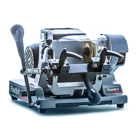
Jepson 9435 T3 User manual

1
(6
6
U
)
FOR YOUR
SAFETY
Read the manual Wear protective goggles Wear ear protector Wear protective
gloves
Operation Instructions
E
NGLISH
FRAN AIS

A
S
C
D
A
12B3
C
A
A
A
C
B
B4
5
6
AA
B
78 9
A
A
11 12
A
13
10
2
1

Certificate
------ CA 72193630 01
Certificate no.
1
A
.. ®
TUVRheinland
License Holder:
JEPSON Power GmbH
Ernst-Abbe-Str. 5
52249 Eschweiler
Germany
Testreportno.:
USA- 50296051 001
ClientReference:
Mrs. Nikola Nestler
Testedto:
CSA C22.2 NO. 71.2-10 + Gil
Certified Product:
14" Premium Super Dry Cutter
Model Designation: 9435
Rating:
Rated Speed:
AC 115V, 50/60Hz, 15A, 14"xl"
1300/min
Appendix: 1, 1-3
Licensed Test mark:
License Fee -Units
7
7
Date of Issue
(day/mo/yr)
01/11/2019
TUV Rheinland of North America, lnc., 12 Commerce Raad, Newtown, CT 06470, Tel (203) 426-0888 Fax (203) 426-4009
CONFORMITY DECLARATION

4
CONTENTS
1
Instruction manual
Conformity Declaration
Contents
5
5
5
6
7
8
8
1. Short Description
2. Technical Specifications
3. Performance Data
4. Safety Regulations
5. Start-up
6. Operation
6.1 Adjusting the tensioning device
7. Standard Equipment
8. Correct Cutting Procedure at 90°
9. Recommendations
10. Warranty
8
8
8
8
6.1.1 Positioning of the rear chuck jaw base
6.1.2 Work piece clamping
6.1.3 Vice settings
6.1.4 Quick release fastener
9
6.2 Replacing the saw blade
11
11
11
6.3 Cutting technique
6.4 Chip box
6.5 Transporting the Premium Super Dry Cutter
12
12
13
FOR YOUR
SAFETY
Read the manual Wear protective goggles Wear ear protector Wear protective
gloves
14

5
1.SHORT DESCRIPTION
The construction saw PREMIUM SUPER DRY CUTTER is designed and built
according to current international standards of the machine tool industry.
The machines comply with the current regulations for emissions and safety at work,
in particular the rules for the prevention of accidents.
IMPORTANT
If changes are made to a machine without our authorisation, the certificate, the
warranty and the liability are no longer valid.
2. TECHNICAL SPECIFICATIONS
PREMIUM SUPER DRY CUTTER
Voltage
Performance
Saw blade
Saw blade
Number of teeth
Speed
Peripheral speed
Mitre cutting one side
Surface area
Weight
Sound pressure level
Sound power level
Hand and arm vibration
Protection class
110 VAC, 60 Hertz
2400 W (9,6 A)
Ø14'' x 0.087''/0.07'' x 1.00''
Ø355 mm x 2,2/1,8 mm x 25,4 mm
90
1300 rpm (idling)
1450 m/min (idling)
15° - 30° - 45°
480 x 290 mm / 18.9'' x 11.4''
23,5 kg / 51.8 lbs without saw blade
100 dB(A)
113 dB(A)
1,19 m/s2
/ II
3.PERFORMANCE DATA
PREMIUM SUPER DRY CUTTER
max. Ø mm/ inches
max a x b 90° 45°
140 mm / 5.5''
125 mm / 4.9''(inox)
102 mm
125x125 mm
80x80 mm
105x155 mm 75x100 mm
4.9''x4.9''
4.13''x6.1''
4.02''
3.15''x3.15''
2.95''x3.94''
90x180mm
3.54''x7.09''

6
4.SAFETY REGULATIONS
1. The safety device may not be removed during the working process and must always be
kept operational.
2. The adjustment keys and wrenches must be removed before the machine is turned on.
3. The workspace is to be kept tidy since an untidy working environment is the cause of
accidents.
4. The machine should not be used in a dangerous environment, e.g. an environment
containing inflammable fluids or gas.
5. Children and all visitors must also be kept away from the workspace.
6. The workshop must be secured with a padlock or master switches.
7. The machine must not be overloaded.
8. Only original parts may be used. Only cut materials suitable for the machine and the saw
blade.
9. Wear suitable clothing. Do not wear loose clothes, gloves, ties, rings, bracelets or jewellery,
which may get caught in the mobile parts of the machine. Skid-proof shoes are
recommended and the hair should be tied or hair protection should be worn.
10. During work with the machine, safety goggles, protective gloves, and ear protector must be
worn at all times. A face or dust mask should also be work if sawing produces dust.
Regular eyeglasses do not replace safety goggles.
11. The work piece must always be clamped with the vice so that both hands of the operator
are free to operate the machine.
12. Do not lean over the machine during operation and always ensure safe position of the
machine and good balance of the operator.
13. The saw blade must be maintained carefully. It must always be kept in sharp and safe
state, as this is an essential condition for good and safe operation.
14. Pull the power supply plug before changing spare parts, accessories or the saw blade.
15. To reduce the risk of unintentional start-up of the machine, it must be ensured that the
switch is turned OFF before the power plug is inserted into the socket.
16. Use the recommended accessories as the use of incorrect parts can cause accidents.
17. Never stand on the machine. It may tilt and start unexpectedly and cause severe accidents.
18. Damaged parts must be verified and repaired before the machine is used. The safety device
or other damaged parts must be verified carefully to determine whether they operate
properly according to their function. A certified maintenance engineer must verify the
alignment of the mobile parts, the mounting as well as any other factors that may
affect the operation of the machine before the machine is put into operation. All defective
parts must be properly repaired or replaced.
19. Never allow the machine to run unsupervised. Do not leave the machine until the saw
blade stands still.
20. Use only identical original spare parts for maintenance.

7
Additional safety precautions
for the Premium Super Dry Cutter
1. Always clamp the work piece securely.
2. Observe the rotation direction of the saw blade.
3. Ensure that the saw blade is always sharp, is unimpeded and runs without
vibration.
4. Lift the circular cold saw off the work piece before the safety switch is operated.
5. Before sawing, allow the motor to achieve full speed.
6. Operate the machine only if it is properly grounded.
7. Do not reach into the workspace with your hands while the machine is connected
to the socket.
8. Protect the machine against moisture.
9. Wear safety goggles, protective gloves, and ear protector.
10. To prevent unauthorized use, install a padlock through
the intended hole.
The device must not be operated in
a humid environment.
5.START-UP
After unpacking the machine, verify if the content is complete. Make sure to place
the machine on a solid and leveled surface. Loosen the locking bolt. Install the saw
blade according to the instructions in chapter 7.2,
"Replacing the Saw Blade". Before inserting the power supply plug into the socket,
make sure that it is a grounded socket. In the case you are using cable
extensions,
you
must make sure that they are also grounded.

8
6.OPERATION
6.1.
Adjusting the tensioning device
It is important for the safe operation of the circular cold saw as well as for good cut
and a long life of the machine that the work piece is clamped securely.
6.1.1 Positioning of the rear chuck jaw base (Fig.1)
The rear chuck jaw base can set to 3 positions (3 break points) to adjust it
to
different
material dimensions. Loose locking lever A and push down Knob B for the
adjustment, position the chuck jaw base accordingly, and then tighten locking lever
A.
For cuts at angles of 0° (90°), 15°, and 30° of materials up to 25 mm thickness, the
chuck jaw base should be set to medium position. For thicknesses over 25 mm, set it
to the rear position. The right rear stop can be aligned from its rear position
(Figure 3).
6.1.2 Work piece clamping (Fig.1)
Put the work piece between the clamping plate (C) and the rear chuck jaw (D) and
ensure that the tensioning device is tightened with the locking lever (A) in clockwise
direction. In order to set the rear chuck jaw (D) of the vice to the desired angle,
loosen locking lever A and adjust the desired angle. The machine is equipped with
an adjustable back support for the sawing section (Figure 2).
6.1.3 Setting of the right rear stop (Fig.2&3)
The use of the right rear stop (stopper) extends the service life of the saw blade and
is particularly useful in order to avoid that small sections are thrown into the protec-
tive cover.
To do so, loosen the screw C and align the right rear stop in a straight line with the
rear chuck jaw set. Then tighten the screw C again. Depending on the material thick-
ness, insert the screw D into hole A or B.
6.1.4 Quick release fastener (Fig.4)
The quick release fastener permits quick pre-adjusting in order to avoid having to
rotate the clamping fixture too much via the clamping handle to bring it into posi-
tion depending on the work piece size. To do so, turn the locking pin (A) left into a
perpendicular position: You can now pre-adjust the clamping fixture (B) without
screwing. After having done this, turn the locking pin right again so that the thread
engages again. You can now clamp the work piece tight by rotating the clamping
handle.

®
�_
9
6.2. Replacing the saw blade
The blade can be replaced easily by following these instructions:
Step 1
Pull the power supply plug from the socket. Next, put the plug aside so that it cannot
be plugged in accidentally.
Step 2 (Fig. 5)
Loosen the butterfly screw (A), turn the small cover (B) to the rear, pull up the
vibration dampers (C), and lock them by turning them to the side.
Step 3 (Fig. 6&7)
Push in spindle lock (Fig. 6-A). Grip the screw with the hexagonal wrench and
loosen the screw. Turn the face cover up and carefully remove the blade.
Step 4 (Fig. 7)
Push the new blade carefully onto the axle shaft, ensuring that the rotation direction
indicated on the saw blade runs counter-clockwise and the saw blade is grease-free.
Also ensure that the blade rotates in the direction indicated by the arrow on the
protective cover. Next, replace the external flange and the screw and tighten firmly.
Step 5
Turn the small cover back to its original position and tighten the butterfly screw (Fig.
5-A). Move the vibration dampers back to their original position by turning them
(Fig. 5-C).
Step 6
Loosen the spindle lock and ensure that the saw blade can rotate freely (Fig. 6).

10
25
Saw blade guides
Regularly spray the spots where the saw blade comes into contact with the saw blade
guides with lubricating oil spray. Since the vibration dampers are consumption parts,
they should be replaced when they are worn down by approx. 3 mm to a residual
value of 1 mm.
MAINTENANCE:
Replacing the carbon brushes: (Figure 8 and 9)
1. Replace the carbon a brush when they are worn down to approx. 1/4“ (6 mm) or
spark formation occurs. Both brushes must be replaced at the same time.
2. Remove the worn brushes, insert the new brushes and close the cover again.
The carbon brushes must be
replaced by an electrician!
MATERIALS:
-Tubes and profiles made of steel and stainless
steel.

11
26
6.3 Cutting technique
Step 1: The circular cold saw can cut at angles of 45°-90°.
a) For 90°, position the work piece between the clamping plate and the set-
ting up piece and ensure that the clamping
f
ixture is tightened with the
clamping handle in clockwise direction.
b) For 45°, loosen the screw at the setting up piece, set the machine to the
desired angle and re-tighten screws.
Next, insert the work piece and tighten the clamping
f
ixture firmly.
Step 2: On the handle, there is a safety switch (Figure 10). Follow steps 1, 2 and 3.
Ensure that the motor runs load free for a few seconds to reach the maximum opera-
ting speed before you start sawing.
Step 3: Cut slowly and evenly. Lift the handle off the work piece and release the
switch to switch off the saw. Release the handle only after the saw blade comes to a
total standstill.
6.4 Chip box
The chip box (Figure 11) catches up to 80% of the chips.
6.5 Transporting the Premium Super Dry Cutter
If you want to transport the Premium Super Dry Cutter machine, keep the stopper
handle (Figure 12) pulled outward and lower the operating arm to the lowest posi-
tion. Now let the stopper handle engage.
You can now transport the device with the handle.

12
27
7.STANDARD EQUIPMENT:
OPTIONAL PREMIUM SUPER DRY CUTTER:
1. Thinfix (Part no. 600546) (Figure 13-A)
2. Eccentric Clamping System (609910)
3. Saw Blade 14''/355mm x 72T for thick
material (600580)
8.CORRECT CUTTING PROCEDURE AT 90°
Saw Blade 14''/355mm x 90T (600570)

13
28
9.RECOMMENDATIONS
In order to achieve an optimal saw blade performance, please read
the following recommendations:
1. Fasten the work piece well
- First check by hand if the work piece is safely and solidly attached.
- Clamp and cut pipes and round materials individually only.
2. At the beginning insert the carbide tipped saw blade carefully and gently
into the material and then continue sawing quickly.
3. Carefully remove chips deposited between the carbide teeth during the work
before continuing to work.
4. Check the carbide saw blade regularly for abrasion and broken carbide teeth.
If a blade becomes blunt due to wear and broken teeth, replace it with a new one.
5. Always wear safety goggles when sawing.
6. Never reach into the running saw with your hands. Keep clothing away.
7. Watch for the rotation direction when mounting the saw blade.
8. Have saw blades sharpened only by specialised sharpening services.
9. Saw blades can be re-sharpened up to 5 times depending on how they are used.

14
29
10.WARRANTY
The warranty time is 12 months from the day of purchase by the user.
It covers and is limited to the free replacement of the defective parts or the free repair
of defects that are demonstrably due to the use of imperfect materials during
production or due to assembly errors.
Incorrect use or start-up and unauthorised installations or repairs not specified in the
operating instructions void the warranty. Parts that are subject to wear are also exclu-
ded from the warranty. We expressly reserve the right to make decisions on the war-
ranty application. The warranty is cancelled if the device is opened by a third party.
Transport damages, maintenance work as well as damage and malfunctions due to
insufficient maintenance are not covered by the warranty.
For warranty claims, the proof of purchase of the device must be given by presenting
the delivery note, bill, or cash receipt.
As far as it is legal, we assume no liability for any personal, material or consequen-
tial damages, in particular if the device is used differently than for the purpose indi-
cated in the operating instructions, not installed or repaired according to the opera-
ting instructions, or repairs were executed by a layperson.
The warranty excludes wear parts such as:
Switches, flanges, carbon brushes, supportings and
saw blades.
The quality and safety of the JEPSON circular cold saw depends on the exclusive
use of original DRYTECH saw blades. The use of other saw blades may damage the
machines, if they are thicker than 2,2mm/ 0.09'' or have the wrong geometry.
In this case, the manufacturer assumes no liability.
11.Spare parts
For current spare parts list with order numbers please visit our website:
www.jepsonpower.com

1
5
(6
6
U
)
POUR VOTRE
SECURITE
Lisez le mode d’emploi Portez un protège-oreilles
Portez des lunettes de protection Portez des gants de protection
Mode d'emploi

Certificate
------ CA 72193630 01
Certificate no.
1
A
.. ®
TUVRheinland
License Holder:
JEPSON Power GmbH
Ernst-Abbe-Str. 5
52249 Eschweiler
Germany
Testreportno.:
USA- 50296051 001
ClientReference:
Mrs. Nikola Nestler
Testedto:
CSA C22.2 NO. 71.2-10 + Gil
Certified Product:
14" Premium Super Dry Cutter
Model Designation: 9435
Rating:
Rated Speed:
AC 115V, 50/60Hz, 15A, 14"xl"
1300/min
Appendix: 1, 1-3
Licensed Test mark:
License Fee -Units
7
7
Date of Issue
(day/mo/yr)
01/11/2019
TUV Rheinland of North America, lnc., 12 Commerce Raad, Newtown, CT 06470, Tel (203) 426-0888 Fax (203) 426-4009

17
TABLE DES
MATIERES
Manuel d'instruction
15
DECLARATION DE CONFORMITE CE
16
TABLE DES MATIERES
17
18
18
18
19
20
21
21
1. Brève description
2. Caractéristiques techniques
3. Performances
4. Consignes de sécurité
5. Mise en service
6. Utilisation
7. Accessoires standards
8. Mode de coupe correct à 90°
9. Recommandations
10. Garantie
21
21
21
21
6.1.1 Positionnement du socle de la mâchoire arrière
6.1.2 Serrage de la pièce à scier
6.1.3 Réglage de la butée de droite
6.1.4 Système d'étau à serrage rapide22
24
24
24
6.2 Remplacement de la lame
6.3 Méthode de coupe
6.4 Collecteur de copeaux
6.5 Transport
25
25
26
27
POUR VOTRE
SECURITE
Lisez le mode d’emploi Portez un protège-oreilles
Portez des lunettes de protection Portez des gants de protection
6.1. Rélage du dispositif de serrage

18
1.BREVE DESCRIPTION
La scie de montage PREMIUM SUPER DRY CUTTER a été conçue et fabriquée
conformément à la norme internationale en vigueur dans l’industrie des machines-
outils. Les dispositions applicables aux immissions et à la sécurité du travail ont été
respectées, en particulier les règlements en matière de prévention des accidents.
IMPORTANT
Si des modifications sont apportées aux machines sans notre approbation, le certifi-
cat, la garantie et notre responsibilité ne sont plus d'application.
2.CARACTERISTIQUES TECHNIQUES
PREMIUM SUPER DRY CUTTER
Tension
Puissance
Lame
Lame
Nombre de dents
Nombre de tours
Vitesse périphérique
Coupe de biais
Surface
Poids
Niveau de pression du bruit
Niveau de puissance du bruit
Vibrations mains bras
Indice de protection
3.PERFORMANCES
PREMIUM SUPER DRY CUTTER
max. Ø mm/inches
max a x b 90° 45°
110 VAC, 60 Hertz
2400 W (9,6 A)
Ø14'' x 0.087''/0.07'' x 1.00''
Ø355 mm x 2,2/1,8 mm x 25,4 mm
90
1300 tpm (marche à vide)
1450 m/min (marche à vide)
15° - 30° - 45°
480 x 290 mm / 18.9'' x 11.4''
23,5 kg / 51.8 lbs sans lame
100 dB(A)
113 dB(A)
1,19 m/s2
140 mm / 5.5''
125 mm / 4.9''(inox)
102 mm
125x125 mm
80x80 mm
105x155 mm 75x100 mm
4.9''x4.9''
4.13''x6.1''
4.02''
3.15''x3.15''
2.95''x3.94''
90x180mm
3.54''x7.09''
/ II

19
4.CONSIGNES DE SECURITE
1. Pendant le processus de travail, ne pas enlever le dispositif de sécurité et toujours le
maintenir en service.
2. Avant de mettre la machine en marche, enlever les clés de réglage et les clés à vis.
3. Maintenir la zone de travail propre car un environnement de travail en désordre est
souvent à l’origine de nombreux accidents.
4. Ne pas utiliser la machine dans un environnement dangereux, par exemple sous la pluie.
L’aire de travail doit être bien éclairée. Ne pas utiliser la machine à proximité de liquides
inflammables ou de gaz.
5. Les enfants et tous les visiteurs doivent également être maintenus à distance de l’aire
de travail.
6. Veiller à ce que les enfants n’aient pas accès à l’atelier en prévoyant un cadenas,
des interrupteurs généraux ou en éloignant les clés de démarrage.
7. Ne pas soumettre la machine à des charges excessives.
8. Utiliser uniquement des pièces d’origine. Ne scier que des matériaux pour lesquels
la machine et le disque sont appropriés.
9. Porter des vêtements adéquats. Ne pas porter de vêtements larges, des gants, cravates,
bagues, bracelets ou bijoux qui pourraient se prendre dans les parties mobiles de la
machine. Il est recommandé d’utiliser des chaussures antidérapantes, d’assembler les
cheveux ou de porter une protection pour les cheveux.
10. Pendant l’utilisation de la machine, toujours porter des lunettes de protection, des
g
a
n
t
s d
e
protection et un protège-oreilles. Porter également un masque de sûreté ou un masque
anti-poussière si le sciage engendre la formation de poussière. Les lunettes normales ne
sont pas considérées comme des lunettes de protection.
11. Toujours serrer l’outil à l’aide de l’étau afin de libérer les deux mains et de pouvoir
manier la machine.
12. Pendant le travail, ne pas se pencher au-dessus de la machine et toujours veiller à ce
que la machine ait une assise sûre et que l’opérateur soit en équilibre.
13. Entretenir le disque avec soin. Il doit toujours être aiguisé et propre, seul moyen d’assurer
une utilisation sûre et adéquate.
14. Retirer la fiche avant de remplacer des pièces, des accessoires ou la lame.
15. Afin d’éviter le risque de mise en marche involontaire de la machine, s’assurer que le
commutateur est en position OFF (hors service) avant d’introduire la fiche dans la prise.
16. Employer l’accessoire recommandé car l’utilisation de mauvaises pièces peut engendrer
des accidents.
17. Ne jamais se mettre sur la machine. Elle pourrait se renverser et se mettre
involontairement en marche et causer ainsi des accidents graves.
18. Avant d’utiliser les machines, examiner les pièces endommagées et les réparer.
Le dispositif de sécurité ou d’autres pièces endommagées doivent être examinés avec soin
afin de déterminer s’ils sont utilisés conformément à leur fonction. La disposition de
pièces mobiles, de la fixation ainsi que toutes les autres circonstances qui peuvent
influencer le fonctionnement de la machine doivent être examinées par un technicien
d’entretien agréé avant de mettre la machine en service. Toutes les pièces défectueuses
doivent être convenablement réparées ou remplacées.
19. Ne jamais laisser la machine sans surveillance. Ne quitter la machine que lorsque
la lame est arrêtée.
20. Pour l’entretien, utiliser uniquement des pièces identiques aux pièces d’origine.

20
Mesures de sécurité supplémentaires pour la Premium Super Dry
Cutter
1. Toujours fixer la pièce fermement dans la glissière.
2. Introduire uniquement la pièce dans le sens contraire de la rotation de la lame.
3. S’assurer que la lame est toujours aiguisée et qu’elle tourne librement et sans
vibrations.
4. Détacher la scie circulaire à froid de la pièce avant d’actionner l’interrupteur à
poussoir.
5. Avant de scier, permettre au moteur d’atteindre son plein régime.
6. N’actionner la machine que lorsqu’elle est correctement reliée à la terre.
7. Ne pas mettre les mains dans la zone de travail lorsque la machine est reliée à la
prise femelle.
8. Protéger contre l’humidité.
9. Porter des lunettes de protection, des gants de protection et des protège-oreilles.
10. Pour éviter toute utilisation non autorisée, installez un
cadenas à travers le trou prévu.
Ne pas utiliser l'appareil
dans un environnement humide
5.MISE EN SERVICE
Après avoir sorti la machine de la boîte de transport, vérifier si la livraison est com-
plète. Placer la machine sur une surface lui permettant d’être aussi stable et
plane
que
possible. Libérer la tige de fixation. Monter la lame conformément aux instruc-
tions figurant au chapitre 7 “Remplacement de la lame”. Avant d’introduire la fiche
de l’appareil dans la prise, s’assurer qu’il s’agit d’une prise de terre. En cas d’utili-
sation d’une rallonge, veiller à ce qu’elle soit également mise à la terre.
Other manuals for 9435 T3
1
This manual suits for next models
1
Table of contents
Languages:
Other Jepson Cutter manuals

