Jesco EASYPOOL SMART 02 User manual

EASYPOOL SMART 02
Water sampling station for private swimming pool applications
EN 01
Dosing
Conveying
Control
Liquids
Gases
Systems
Operating Manual
Read this operating manual before start-up!
To be retained for future reference.

2 | EASYPOOL SMART 02 Operating Manual
Table of Contents
Table of Contents
1. Safety Instructions .............................................................................. 3
1.1 General ................................................................................................ 3
1.2 Identification of safety instructions in this operating manual..................... 3
1.3 Operators qualification and training........................................................ 3
1.4 Electrical safety tips .............................................................................. 3
1.5 Hazards due to failure to follow safety instructions .................................. 3
1.6 Safety-conscious working...................................................................... 3
1.7 Safety instructions for the operator......................................................... 3
1.8 Safety instructions for installation, maintenance and inspection................ 4
1.9 Self-made modifications and spares procurement................................... 4
2. Before start-up .................................................................................... 4
2.1 Use for intended purpose....................................................................... 4
2.2 Scope of delivery .................................................................................. 4
2.3 Steps to start-up................................................................................... 4
3. Water sampling station ....................................................................... 5
3.1 Swimming pool water system ................................................................ 5
3.2 Versions ............................................................................................... 6
3.3 Dimensioned drawing............................................................................ 7
3.4 Water sampling station components....................................................... 7
3.5 Water sampling station technical data .................................................... 7
4. Controller ............................................................................................. 8
4.1 Technical data....................................................................................... 8
4.2 Product design...................................................................................... 9
4.3 Terminal diagrams for the main board and technical assemblies ............ 10
4.4 Operation and menu structure ............................................................. 17
4.5 Measurement value inputs................................................................... 18
4.6 Explanation of digital inputs ................................................................. 21
4.7 Control outputs ................................................................................... 22
4.8 Controllers.......................................................................................... 22
4.9 Alarms ............................................................................................... 24
4.10 Analogue power outputs 0/4 … 20 mA for remote displays................. 25
4.11 Controlling the flocculant pump.......................................................... 25
4.12 Service menu ................................................................................... 25
4.13 Memory card .................................................................................... 27
4.14 Connecting to the PC ........................................................................ 27
5. Installation and Commissioning ....................................................... 29
5.1 Tools required ..................................................................................... 29
5.2 Wall mount ......................................................................................... 29
5.3 Electrical connection ........................................................................... 29
5.4 Connection to the pool water circuit ..................................................... 29
5.5 Fitting and calibrating sensors ............................................................. 31
5.6 Starting automatic mode ..................................................................... 32
6. Shutdown, Recommissioning and Disposal ..................................... 33
7. Maintenance and Care....................................................................... 34
7.1 Regular inspection .............................................................................. 34
7.2 Annual maintenance............................................................................ 34
7.3 Adjusting the flow monitor (insufficient sample water)............................ 34
7.4 Peristaltic pump maintenance.............................................................. 34
8. Spare parts, Consumables and Accessories .................................... 35
9. Troubleshooting ................................................................................. 36
9.1 Troubleshooting and diagnostics .......................................................... 36
9.2 Fault resolution ................................................................................... 37
Device revision ...................................................................................... 37
Index ...................................................................................................... 38
CE declaration of conformity................................................................ 41
Declaration of no objection................................................................... 42
Warranty claim....................................................................................... 43
Dear Sir or Madam,
We are delighted you have chosen your EASYPOOL SMART 02
water sampling station. For over 50 years the name Jesco has
stood for innovative products in dosing technology, measurement
and control and water analysis. EASYPOOL SMART 02 continues
a successful product line of high quality water sampling sta-
tions.
Lutz-Jesco GmbH
Please note:
The water sampling station must be set up by someone with spe-
cialist knowledge of swimming pool technology and the bathing
water must be disinfected. Contact the engineer responsible for
installing your swimming pool if necessary.
To ensure full, unrestricted use of the product it must be han-
dled professionally during set-up, operation and servicing. You
should therefore read this operating manual before working on
the equipment.

EASYPOOL SMART 02 Operating Manual | 3
Safety Instructions
1. Safety Instructions
1.1 General
This manual contains very important information for assembly,
start-up, use and maintenance of the meter. The manual must
be read by all staff and any person in charge of the unit before
starting work on the equipment. Store the manual safely in a
place where mechanics, installers and other technical staff as
well as operators can rapidly access it in case of emergency. Pay
special warning and provide compliance with all safety notices
in this manual!
1.2 Identification of safety instructions in this operating
manual
This Operation & Maintenance Manual contains vital information
which may endanger people and the unit if they are disregarded.
These statements are identified by the following symbols:
WARNING!
Refers to a potentially hazardous situation. Failure to
follow this instruction may lead to death or extremely
serious injuries.
CAUTION!
Refers to a potentially hazardous situation. Failure to
follow this instruction may lead to minor injuries or
damage to property.
IMPORTANT! or NOTICE!
Failure to follow these safety instructions may en-
danger the machine and its functions.
IMPORTANT!
This indicates additional information that makes work
easier and ensures trouble-free operation. Notes
attached directly to the unit, e.g. cable references,
directly must be observed and kept in a fully legible
condition for future reference.
1.3 Operators qualification and training
Your assembly, operation, maintenance and inspection staff must
be trained and have the appropriate qualification for use and op-
eration of the unit. Area of responsibility, tasks and supervision
of the personnel must be provided at all times by the customer.
Unskilled operators must be duly trained and instructed. If neces-
sary, this can also be undertaken by the manufacturer or certi-
fied supplier on behalf of the owner. Operators who are to work
with the meter must read and understand the manual in all of
its parts.
1.4 Electrical safety tips
Basic safety precautions should always be followed when install-
ing and using this electrical equipment. These precautions in-
clude the following:
WARNING!
1.) Read and follow all instructions.
2.) To reduce the risk of injury, do not permit children
to use this product unless they are closely super-
vised at all times.
3.) Risk of electric shock. Ensure that the device is
secured with an earth-leakage circuit breaker (GFCI).
Contact a qualified electrician if you cannot verify
that the receptacle is protected by a GFCI.
4.) Do not bury the cable. Locate cord to minimize
abuse from lawn mowers, hedge trimmers, and
other equipment.
5.) To reduce the risk of electric shock, replace the
cable immediately if damaged.
6.) To reduce the risk of electric shock, do not use an
extension cable to connect the device to the power
supply; use an appropriately located outlet socket.
7.) Keep this instruction at close for future refer-
ence.
ATTENTION!
The device is not suitable for installation in explosive
areas.
1.5 Hazards due to failure to follow safety instructions
Failure to comply with the safety instructions may endanger not
only people, but also the environment and the unit. Non com-
pliance with the safety information will immediately cancel your
rights of claiming for damages even during the warranty period.
The following hazards in particular may arise: - Failure of system
functions. - Danger to people due to electrical, mechanical and
chemical effects. - Danger to the environment due to leakage of
hazardous substances.
1.6 Safety-conscious working
The safety instructions contained in this operating manual must
be observed. The operating company is responsible for ensuring
compliance with local safety regulations. Disturbances suscepti-
ble of impairing safety are to be eliminated immediately!
1.7 Safety instructions for the operator
Statutory regulations must be observed. A safe and ecologically
beneficial disposal of process materials as well as replacement
parts must be ensured. Danger due to electric current must be
excluded (for further details, refer to the German VDE1) standards
as well as local rules and regulations as well as chapter 1.4).
1) Association of German Electrotechnical Engineers

4 | EASYPOOL SMART 02 Operating Manual
Before start-up
1.8 Safety instructions for installation, maintenance and
inspection
The operator has to ensure that all assembly, maintenance and
inspection works are done by authorized and qualified technical
operators.
WARNING!
Assembly and maintenance of the equipment are
to be strictly done after disconnecting the device
from the power supply. It must be secured against
reconnection during the works! Auxiliary assemblies
and tools should be dismounted prior to maintain-
ing. Cables are to be attached likewise only in this
condition.
Neglecting of these instructions can lead to severe damages of
device and loss of warranty.
All safety mechanisms and guards must be refitted and reacti-
vated as soon as the work is complete.
NOTICE!
Apart from an incorrect installation also wrong con-
troller settings (default settings, data of the param-
eter and configuration level, and internal changes of
the instrument) can impair or damage the process
normal functions.
There should always be a safety device that is independent of the
controller. Configurations may only be carried out by technical
personnel! If necessary use password protection! Always comply
with the safety regulations and accident prevention laws of the
country of use.
1.9 Self-made modifications and spares procurement
The device may be converted or changed only by qualified tech-
nical personnel.
If the device is incorrectly configured by assembly or service
personnel, faults and hazards can arise during operation. In this
case, the manufacturer declines any liability.
NOTICE!
Genuine spare parts and sensors authorized by the
manufacturer ensure greater safety. Otherwise the
guarantee expires.
NOTICE!
Local safety instructions and applicable regulations
must be observed. The operating manuals of prod-
ucts used in the system must be observed, in par-
ticular the operating manual of the peristaltic pump
which is included separately with the water sampling
station.
2. Before start-up
2.1 Use for intended purpose
The EASYPOOL SMART 02 water sampling station is solely de-
signed for sampling and control applications in the preparation of
swimming and bathing water in swimming pools and whirlpools
not operated in accordance with DIN 19643. The operational
safety of the delivered unit can only be guaranteed when it is
used in conformity with its intended use.
Use for any other purpose is not permitted and will invalidate any
liability under the warranty.
2.2 Scope of delivery
Carefully check the delivery prior to installation to ensure the de-
livery is complete and to check for any transport damage. Con-
tact the supplier and/or carrier regarding any questions concern-
ing the delivery and/or transport damage.
Do not operate defective devices.
Items fixed to the EASYPOOL SMART 02 include:
TOPAX DX SMART controller
Temperature gauge (depending on model)
1-2 peristaltic pumps (depending on model)
Chlorine measuring cell (depending on model)
Wall holder
0
9
3
66
1
5
:;
87
4
2
Fig. 2.1: Accessories supplied
Also included in the scope of delivery are:
a Mounting material
b 3 connections with ball valve
c 1-2 suction lines (depending on model)
d 1-2 Injection nozzles (depending on model)
e 1-2 x 5 m pressure line hose (depending on model)
f 10 m sample water line hose
g 2 sample water connections with G 1/4 male thread
h REDOX electrode (depending on model)
i pH electrode
j Buffer solutionsfor the pH- (6.8 and 9.27 pH) and REDOX
electrodes (465 mV)
k Set of decals for use on the water sampling station
l "Chlorine bleach..." warning decal (depending on model)
2.3 Steps to start-up
After reading the operating manual, assembly and start up the
equipment as detailed in chapter 5.
•
•
•
•
•

EASYPOOL SMART 02 Operating Manual | 5
Water sampling station
3. Water sampling station
The EASYPOOL SMART 02 water sampling station is a precise
tool for maintaining auxiliary bathing water hygiene parameters.
The EASYPOOL SMART 02 is highly compact and easy to use.
The base plate contains holes for guiding the water and housing
the sensors. As a result there is no need for external piping and
fittings and the water sampling station is highly compact.
The plate of the EASYPOOL SMART 02 water sampling station
contains all the components needed for controlled, optimum dis-
infection of the bathing water.
These include:
Several sensors for measuring the water values,
Valves, taps and connections
TOPAX DX SMART multi-channel controller (see chapter 4)
- to analyse the readings,
- to provide controlled supply of chemicals,
Pumps to deliver the chemicals.
0
12
4
3
5
Fig. 3.0: EASYPOOL SMART 02 water sampling station with TOPAX DX SMART
a, peristalitic pumps(s) b, Chlorine measuring cell c(depending
on model), needle valve d, temperature gauge e(depending on
model) and pH electrode f
The water sampling station is connected to the swimming pool
water system. All the items required for inclusion in the system
and for disinfection are either contained on the sampling station
or provided as accessories.
•
•
•
•
3.1 Swimming pool water system
In a typical installation a circulation pump delivers the bathing
water through a filter. When the disinfectant and the pH-adjust-
ing solution (normally a pH reducing agent) have been added, the
water returns to the pool via inlet nozzles. The water sampling
system is incorporated in this system.
IMPORTANT!
A continuous flow of water is required to achieve suc-
cessful sampling and control of the water quality. Any
deviations in the flow velocity and frequent interrup-
tions to the flow will have a negative effect on the
control system and hence the water quality.
The following functional diagram illustrates the instal-
lation.
a
g
e
d
c
b
f
h
Fig. 3.1: Functional diagram of a swimming pool water system with an overflow
channel
aSwimming pool
bSplash water tank
cCirculation pump
dFilter
eSample water removal
fSample water return
g Injection nozzles for disinfectant and pH-adjusting solution
h Sample water filter

6 | EASYPOOL SMART 02 Operating Manual
Water sampling station
3.2 Versions
The EASYPOOL SMART 02 water sampling station comes in different versions.
The following overview shows the options:
Item no. Disinfectant Control
system
Sampling system
RS 485
Free chlorine REDOX
pH
Tem-
pera-
ture
Conductivity
Salt water Salt water
42401002
Chlorine bleach
Chlorine,
pH value
Yes - -
Yes
-
-
-
42401102 - Yes
42401005 Yes -
42401014 - Yes -
42401003
REDOX
pH value - Yes -
- -
42401004 Yes -
42401000 Active oxygen - -
42401010
Flow-through chlorine electrolysis,
0 … 20 mA
Chlorine,
pH value
- Yes -
Yes
- -
42401001 Chlorine,
pH value,
Conductivity
0 … 20 mS/cm
-
42401006 Yes
42401011 Flow-through chlorine electrolysis,
ON/OFF
Chlorine,
pH value - - -
42401007
Flow-through chlorine electrolysis,
0 … 20 mA
REDOX,
pH value
- - Yes
- - Yes
42401009
REDOX,
pH value,
Conductivity
- 0 … 20 mS/cm -
42401008
Flow-through chlorine electrolysis,
ON/OFF
REDOX,
pH value - - -
42401012
REDOX,
pH value,
Conductivity
- 0 … 20 mS/cm -
42401016 REDOX,
pH value Yes - Yes
Table 3.2: EASYPOOL SMART 02 versions

EASYPOOL SMART 02 Operating Manual | 7
Water sampling station
3.3 Dimensioned drawing
465
504
385
454
167
454
504
167
465
385
1
234
⑮
6
8
⑬;
9
5
:
0
7
⑭
⑯
⑰
Figs. 3.3.1 and 3.3.2: EASYPOOL SMART 02 with 2 peristaltic pumps (left) and EASYPOOL SMART 02 with conductivity transmitter and one peristaltic pump (right)
3.5 Water sampling station technical data
Water sampling station
Free chlorine sensor 2-electrode measuring cell with
automatic electrode cleaning
Platinum/copper electrodes
(platinum/silver for salt bathing
water)
0 … 10 mg/l
REDOX potential sensor Single rod measuring cell
Platinum electrode (gold for salt
bathing water)
0 … 1000 mV
pH value sensor Single rod measuring cell
Glass membrane electrode
2 … 12 pH
Temperature sensor Resistance thermometer
Pt100 electrode
0 … +80 °C
Conductivity sensor Conductive measuring cell
Stainless steel / PP electrode
Output signal 4 … 20 mA
0 … 20 or
0 … 60 mS/cm
Operating pressure 0.2 . . . 3 bar
Operating temperature 5...40 °C
Water requirement approx. 45 l/h
Weight approx. 11 kg
Hydraulic connections Clamped connection for 6/8 mm PE tubing
Conductivity transmitter
Power supply 230 V AC, 50 … 60 Hz
Output signal 4 … 20 mA
Working resistance load max. 800 Ω
Protection class IP 65
Ambient temperature max. 55 °C
Housing PP
Peristaltic pump
Power supply 230 V AC, 50 Hz
See also attached peristaltic pump operating manual.
3.4 Water sampling station components
aWater sampling station
bTOPAX DX SMART controller
cConductivity sensor (depending on model)
dpH sensor
eREDOX sensor (depending on model)
fTemperature sensor (depending on model)
gFree chlorine sensor (depending on model)
hFlow monitors
iSampling water inlet with stop valve
jSampling water outlet with stop valve
kWater sample tap connection
lDisinfectant peristaltic pump
⑬pH-adjustment solution peristaltic pump
⑭Wall holder
⑮Needle valve for flow control
⑯Hinges
⑰Anti-oscillation retaining screw
rConductivity transmitter
r

8 | EASYPOOL SMART 02 Operating Manual
Controller
4. Controller
The EASYPOOL SMART 02 water sampling station is equipped with the TOPAX DZ SMART multi-channel controller. This device uses the
TOPAX DX technology designed for public swimming pools and has been specially configured for use in non-DIN 19643 operated swim-
ming pools. It features a graphic colour display, an intuitive user interface with support for the installation and maintenance of the water
sampling station.
4.1 Technical data
Power supply 90 … 264 V AC, 47 … 63 Hz
Power consumption approx. 24 W
Housing dimensions 302 x 231 x 108 mm (W x H x D) wall mounted unit
Display Graphic colour display 5.7 inch, 320 x 240 pixels (RGB), with background lighting
Keyboard Keypad
Measuring inputs
(potential-free)
• Free chlorine
• pH value
• REDOX potential
• Temperature
• 4 … 20 mA for conductivity (passive)
Regulating characteristic for 3 inputs
(free chlorine, pH value, conductivity)
P, PI, PD or PID performance
Disinfection output also with timer control system
Control parameters Xp: 1 … 500%, Tn: 1 … 200 minutes, Tv: 1 … 1200 seconds
Measuring input Free chlorine Open amperometric measuring cell with mechanical cleaning (excess chlorine detector with 2 electrodes, CS120)
Measuring range adjustable between 0 … 1, 0 … 2, 0 … 5 or 0 … 10 mg/l. Connected via series terminals*
pH value 0 … 14 pH, input resistance 109Ω connection via line-up terminals*
REDOX potential 0 … 1000 mV, input resistance 109Ω
Temperature -10 … +150 °C
Conductivity conductiv or inductive
with separate measuring amplifier
20 mA type, measuring range depending on type of measuring amplifier
Digital inputs • Early warning level input for disinfectant
• Warning level input for disinfectant
• Early warning level input for pH adjustment solution
• Warning level input for pH adjustment solution
• Filter cleaning: disconnection of the controller function without alarm
• Insufficient sample water: disconnection of the controller function with alarm
2-3 control outputs Digital output (optocoupler) 48 V DC, 250 mA (pulse frequency 10 … 200 pulses/min)
Relay output • ON/OFF
• Pulse frequency 10 … 100 pulses/min
• Pulse length 10 … 120 seconds
Continuous analog output 0/4 … 20 mA, max. working resistance 500 Ω
Alarm output Relay output as common alarm for all readings
Measuring value alarm min. and max. alarm freely adjustable, adjustable time delay: max. 200 min
Safety shut off To prevent overdosing (Y alarm), time delay adjustable: max. 200 min
Current outputs to remote transmission of
measuring values
• Free chlorine
• pH value
• REDOX potential
• Temperature and conductivity
0/4 … 20 mA possible spreading; max. working resistance 500 Ω potential free
average spreading >50 % with measuring input free chlorine and 0/4 ... 20 mA
>10 % with measuring input pH value and REDOX potential
Computer interface (optional) RS 485
Support battery VARTA CR 1/2 AA 2 V lithium (soldered in), useful life approx. 5 … 10 years
Load capacity of the relay 230 V AC, 3 A
Protection class IP 65 with locked screw connections
Ambient temperature -5 … +45 °C
Atmospheric moisture 95 % non-condensing
*) max. 0.5 mm² with cable ends protection sleeve and max. 1.0 mm² without cable end sleeve.

EASYPOOL SMART 02 Operating Manual | 9
Controller
4.2 Product design
The front housing aand the rear housing bof the controller
are fitted together with two pivots (cand d) (see Fig. 4.2).
The unit is designed so that the controller can be opened from
either side.
db
c
a
e
f
Fig. 4.2: Housing structure
aFront housing
bRear housing
cHinge pivot (fitted)
dHinge pivot (disassembled)
ePivot head (screw-on)
fPivot disassembly tool
Opening the casing
To open the housing it is preferable to remove the right pivot. To
do this, unscrew head eof the pivot.
NOTICE!
In order to open the housing remove only one hinge
pivot from the equipment. If both bolts are removed
at the same time, the upper part and the lower part
of the box will fall loose.
NOTICE!
The equipment is to be opened only when plugged
off the power supply.
reare housing
The rear housing contains the main board with slots for the func-
tional assemblies. Depending upon the model, two input blocks
are available together with an output block. For create a network
connected to a PC, an interface assembly (RS 485) can also be
installed. All blocks are connected by plug connectors to the main
board and fastened with several nuts.
front housing
On the front housing there are the display plate and the key-
board. A colour display is available for displaying measurements
and adjustments. The display board contains the memory card
slot.
10 | EASYPOOL SMART 02 Operating Manual
Controller
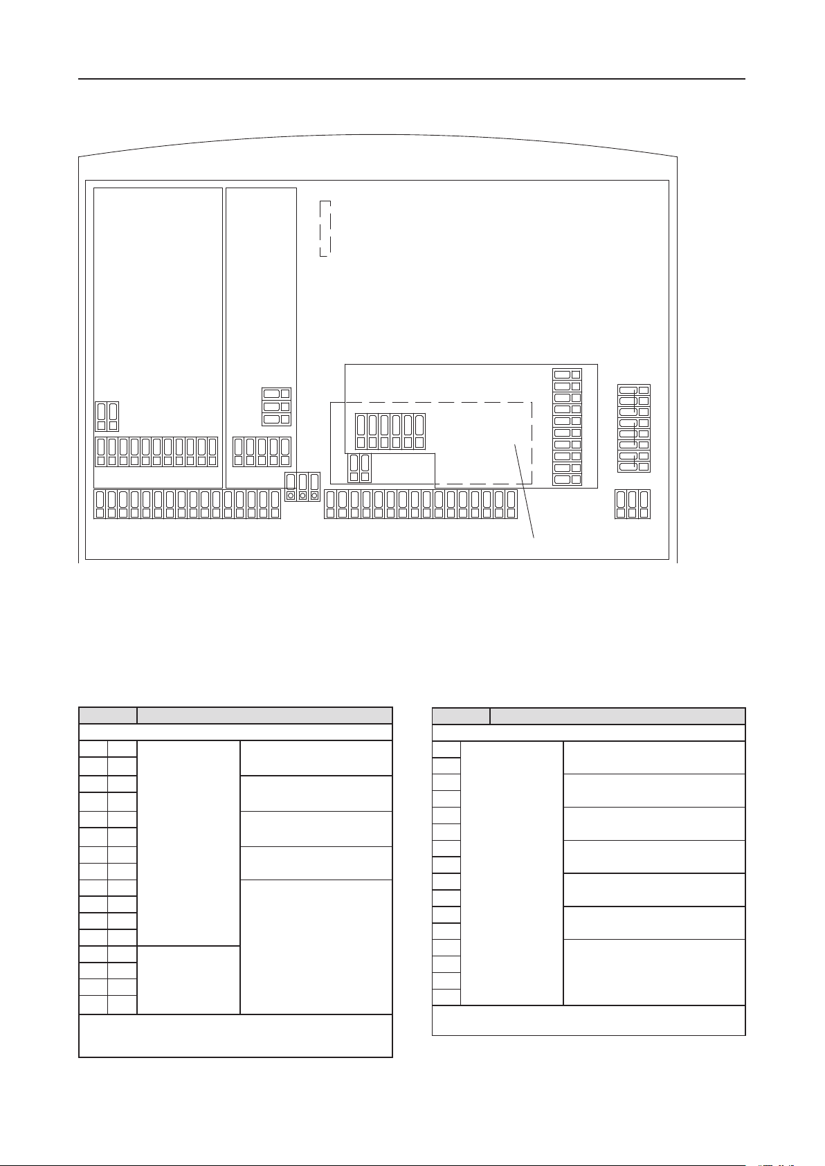
4.3 Terminal diagrams for the main board and technical assemblies
DO4 DO3 DO2 DO1
78404
78403
78402
DO7 DO6 DO5
DO0
78399
78406
+-
+-
+-+-+-+-+-+-
1
2
3
4
5
6
7
8
9
10
11
12
13
14
15
16
17
18
19
20
21
22
23
24
25
26
27
28
29
30
31
32
36
37
38
PE
N
L
33
34
92
93
94
87
88
89
90
91
86
-+
81
82
83
84
85
- -+ +
56
57
58
59
60
-+
51A
52A
53
54
55
61
51B
52B
- -+ +
-
+
71
72
73
74
75
76
77
78
39
40
41
43
44
45
46
42
35
95
96
B
A
Fig. 4.14: Rear housing with the "78402" main board, input module "78403" (5x), input module "78404" (3x), output module "78399" and the partially hidden PC
interface "78406".
Main board (order no. 78402)
Terminal Function
Analogue power outputs 0/4 … 20 mA (see also chapter 4.10)
1 + Measurement value
output
0/4...20 mA
Disinfection
2 -
3 + pH value
4 -
5 + Temperature
6 -
7 + Salt content
8 -
9 + Programmed as controller output***
10 -
11 +
12 -
13 + Continuous controller
output
0/4...20 mA
14 -
15 +
16 -
***) The routing of the configurable outputs is displayed according to the
configuration and can be selected at any time in the Service >> HW-Status
menu
Terminal Function
Digital inputs
17 Potential free input Insufficient sample water *)
18
19 Filter cleaning *)
20
21 Level input pre-alarm
Disinfectant **)
22
23 Level input alarm
Disinfectant **)
24
25 Level input pre-alarm
pH adjusting solution **)
26
27 Level input alarm
pH adjusting solution **)
28
29 not used
30
31
32
*) normally ON or normally OFF
**) normally ON or normally OFF or not active

EASYPOOL SMART 02 Operating Manual | 11
Controller
Terminal Function
33 A Internal
PC interface
Interface for software-update
34 B
35
36 Alarm relay as com-
mon alarm
Normally Closed (N.C.)
37 Middle contact
38 Normally Open (N.O.)
39 PE Protection conductor 90 … 264 V AC
40
41 N Neutral conductor
42
43
44 L Phase
45
46
5-fold Input block (part no. 78403):
Terminal Function Cable colour
51A + Free chlorine
Chlorine measuring cell CS120
Electrode mating copper/platinum or
silver/platinum
CS120 (Cu/Pt)
Cu : blue (-)
Pt : red (+)
CS120 (Ag/Pt)
Ag : purple(-)
Pt : red (+)
52A -
51B + not used
52B -
53 + pH value
54 -
55 + REDOX
56 -
57 Temperature
(Polarity at wish)
58
59 not used
60
61
Input module (3x) (part no. 78404) optional:
Terminal Function
71 not used
72
73
74 + 20 mA passively (without supply to the sensor)
Conductivity measurement
75 -
76 not used
77
78
outputs board (order no. 78399)
Termi-
nal
Output
81 + Digital output
(optocoupler)
DO7 programmable ***)
82 -
83 + DO6
84 -
85 + DO5
86 -
87 Relay output DO4
88
89 DO3
90
91 DO2
92
93 DO1
94
95 DO0
96
***) The routing of the configurable outputs is displayed according to the
configuration and can be selected at any time in the Service >> HW-Status
menu
IMPORTANT!
To prevent the output relays from bonding in the case
of a short in the load circuit, it must be separatly
protected with the maximum relay switching cur-
rent. For inductive loads, apply a protective circuit to
the contacts of the relays (spark suppression). The
manufacturer recommends the use of the interfer-
ence suppression module / spark suppression device
(part no. 78614).
12 | EASYPOOL SMART 02 Operating Manual
Controller
4.3.1 Terminal connection 1: control of two peristaltic pumps (disinfection and pH), free chlorine and pH measurement
78403
78399
+-
+-+-+-+-+-+-+-
1
2
3
4
5
6
7
8
9
10
11
12
13
14
15
16
17
18
19
20
21
22
23
24
25
26
27
28
29
30
31
32
36
37
38
PE
N
L
33
34
92
93
94
87
88
89
90
91
86
-+
81
82
83
84
85
- -+ +
56
57
58
59
60
-+
51A
52A
53
54
55
61
51B
52B
- -+ + 39
40
41
43
44
45
46
42
35
95
96
230 V / 50 Hz
Description Term. Cable Remarks
aChlorine measuring cell CS120 51 A + red (RD) platinum (Pt)
52 A - Blue (BU) Copper (Cu)
purple (VT) Silver (Ag)
bpH single-rod measuring cell 53 + white (WH) Internal lead
54 - black (BK) Screen
dTemperature sensor Pt 100 57/58
eInsufficient sample water
contact
17/18
Description Term. Cable Remarks
fDisinfection peristaltic pump 88 Brown (BN) Relay
41 Blue (BU) N
39 Yellow/green (YE/GN) PE
gPeristaltic pump pH 90 Brown (BN) Relay
41 Blue (BU) N
39 Yellow/green (YE/GN) PE
hpH relay suppression module 90/43 black (BK) Relay / N
iDisinfection relay suppression
module
88/43 black (BK) Relay / N
a
b
d e
f g
h i
EASYPOOL SMART 02 Operating Manual | 13
Controller
4.3.2 Terminal connection 2: control of two peristaltic pumps (disinfection and pH), REDOX and pH measurement
Description Term. Cable Remarks
bpH single-rod measuring cell 53 + white (WH) Internal lead
54 - black (BK) Screen
cREDOX single-rod measur-
ing cell
55 + white (WH) Internal lead
56 - black (BK) Screen
dTemperature sensor Pt 100 57/58
eInsufficient sample water
contact
17/18
Description Term. Cable Remarks
fDisinfection peristaltic pump 88 Brown (BN) Relay
41 Blue (BU) N
39 Yellow/green(YE/GN) PE
gPeristaltic pump pH 90 Brown (BN) Relay
41 Blue (BU) N
39 Yellow/green(YE/GN) PE
hpH relay suppression module 90/43 black (BK) Relay / N
iDisinfection relay suppression
module
88/43 black (BK) Relay / N
78403
78399
+-
+-+-+-+-+-+-+-
1
2
3
4
5
6
7
8
9
10
11
12
13
14
15
16
17
18
19
20
21
22
23
24
25
26
27
28
29
30
31
32
36
37
38
PE
N
L
33
34
92
93
94
87
88
89
90
91
86
-+
81
82
83
84
85
- -+ +
56
57
58
59
60
-+
51A
52A
53
54
55
61
51B
52B
- -+ + 39
40
41
43
44
45
46
42
35
95
96
230 V / 50 Hz
c
b
d e
f g
h i

14 | EASYPOOL SMART 02 Operating Manual
Controller
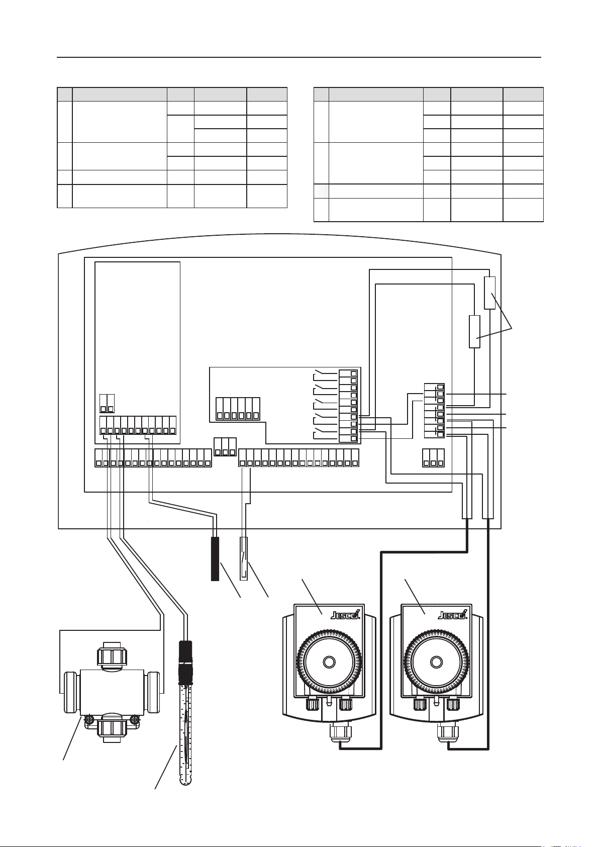
4.3.3 T.C. 3: control of flow-through chlorine electrolysis and peristaltic pump (pH), free chlorine and pH measurement
Description Term. Cable Remarks
aChlorine measuring cell CS120 51 A + red (RD) platinum (Pt)
52 A - Blue (BU) Copper (Cu)
purple (VT) Silver (Ag)
bpH single-rod measuring cell 53 + white (WH) Internal lead
54 - black (BK) Screen
dTemperature sensor Pt 100 57/58
eInsufficient sample water
contact
17/18
Description Term. Cable Remarks
jTechnoline SC 11 / 14
Flow-through chlorine elec-
trolyses
1: power supply unit
2: control unit
3: cable (A/N 91190000)
4: electrolytic cell
87/88 yellow (YE) Relay
gPeristaltic pump pH 90 Brown (BN) Relay
41 Blue (BU) N
39 Yellow/green (YE/GN) PE
ipH relay suppression module 88/43 black (BK) Relay / N
78403
78399
+-
+-+-+-+-+-+-+-
1
2
3
4
5
6
7
8
9
10
11
12
13
14
15
16
17
18
19
20
21
22
23
24
25
26
27
28
29
30
31
32
36
37
38
PE
N
L
33
34
92
93
94
87
88
89
90
91
86
-+
81
82
83
84
85
- -+ +
56
57
58
59
60
-+
51A
52A
53
54
55
61
51B
52B
- -+ + 39
40
41
43
44
45
46
42
35
95
96
230 V / 50 Hz
a
b
d e
j
g
i
1 2
3
4

EASYPOOL SMART 02 Operating Manual | 15
Controller
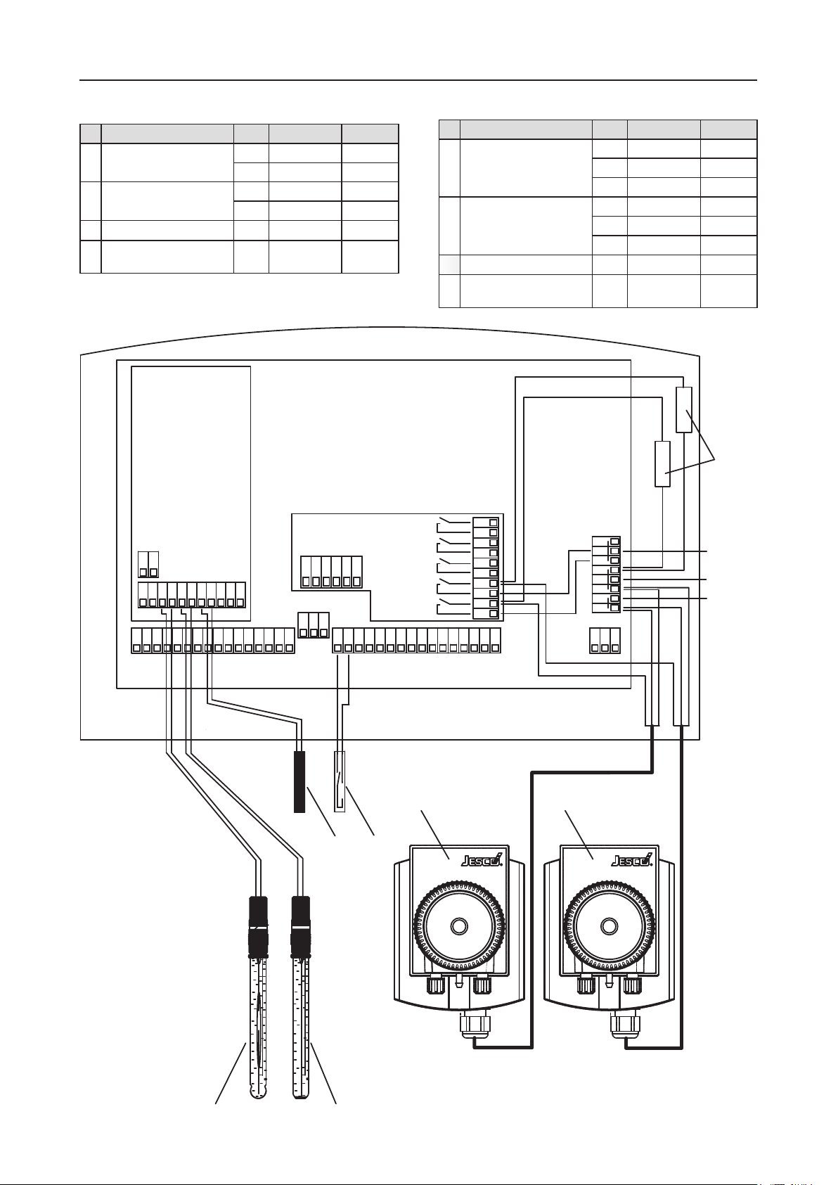
4.3.4 T.C. 4: control of flow-through chlorine electrolysis and peristaltic pump (pH), REDOX and pH measurement
Description Term. Cable Remarks
bpH single-rod measuring cell 53 + white (WH) Internal lead
54 - black (BK) Screen
cREDOX single-rod measur-
ing cell
55 + white (WH) Internal lead
56 - black (BK) Screen
dTemperature sensor Pt 100 57/58
eInsufficient sample water
contact
17/18
Description Term. Cable Remarks
jTechnoline SC 11 / 14
Flow-through chlorine elec-
trolyses
1: power supply unit
2: control unit
3: cable (A/N 91190000)
4: electrolytic cell
87/88 yellow (YE) Relay
gPeristaltic pump pH 90 Brown (BN) Relay
41 Blue (BU) N
39 Yellow/green(YE/GN) PE
ipH relay suppression module 88/43 black (BK) Relay / N
78403
78399
+-
+-+-+-+-+-+-+-
1
2
3
4
5
6
7
8
9
10
11
12
13
14
15
16
17
18
19
20
21
22
23
24
25
26
27
28
29
30
31
32
36
37
38
PE
N
L
33
34
92
93
94
87
88
89
90
91
86
-+
81
82
83
84
85
- -+ +
56
57
58
59
60
-+
51A
52A
53
54
55
61
51B
52B
- -+ + 39
40
41
43
44
45
46
42
35
95
96
230 V / 50 Hz
c
b
d e
g
i
j
1 2
3
4

16 | EASYPOOL SMART 02 Operating Manual
Controller
4.3.5 Terminal connection 5: Conductivity measurement (option)
Description Terminal Remarks
k4 … 20 mA input
Conductivity measurement
74 +
75 -
lRelay output
Conductivity control (e.g. brine dosing)
90 Relay
42 N
Description Terminal Remarks
⑬Power supply
Conductivity transmitter
45 L
41 N
39 PE
⑬Conductivity measuring cell
78403
78399
+-
+-+-+-+-+-+-+-
1
2
3
4
5
6
7
8
9
10
11
12
13
14
15
16
17
18
19
20
21
22
23
24
25
26
27
28
29
30
31
32
36
37
38
PE
N
L
33
34
92
93
94
87
88
89
90
91
86
-+
81
82
83
84
85
- -+ +
56
57
58
59
60
-+
51A
52A
53
54
55
61
51B
52B
- -+ + 39
40
41
43
44
45
46
42
35
95
96
230 V / 50 Hz
4 ... 20 mA
78404
71
72
73
74
75
+-
k
⑬
⑭
l

EASYPOOL SMART 02 Operating Manual | 17
Controller
4.4 Operation and menu structure
4.4.1 Operation
0
1
2
3
4
5
Fig. 4.15: View of TOPAX DX SMART housing with with operating panel.
Keys Functions
Crossed arrow keys
• Menu change-over in the menu "service";
• Change-over between the individual numbers
• Numerical values change, parameter adjust
Press the key to change from one menu item to
the other. Numeric values are entered and modi-
fied continuously.
Key "OK" between
the arrow keys
Input information are received and saved.
Successful saving is notified by a longer beep
Key a: „ESC“ Exit the menu, one level up
Terminate input without storage
Key a: „ESC“
(hold 5 seconds)
Return to the main menu
Keys b- fThe functions of the keys vary according to the
menu and are displayed respectively.
TOPAX DX SMART key layout
If no key is operated, the controller returns automatically to the
measuring mode after approx. 5 minutes. Changed parameters,
which were not confirmed with the “OK” key, are not stored.
Exception: During the calibration and with the configuration no
“time out” takes place.
NOTICE!
If no values are to be changed, "ESC" can be pressed
and the selected menus left at any time. The control-
ler continues working with the old settings. Changed
values are confirmed with the “OK” button. The
"clock" and "timer" functions are exceptions. Their
modification does not require any confirmation.
General rules for entries:
The values can only be changed within the admissible value
range.
The function of the key is signalled with a tone.
Some functions can be password-protected against unau-
thorised access (see chapter 4.12, menu 5.9 "Password").
NOTICE!
An auxiliary function is available for many menu items.
In this case, the "Help" key is shown.
4.4.2 Menu structure
The menus are as a result shown on the display with its col-
oured presentation and high resolution in clear text and clearly
arranged. As a result only the structure is described, not every
detail. (for details of the service menu see chapter 4.12)
Standard display
If there is no entry made within 5 minutes, the device changes to
the standard display (see Fig. 4.4.2.1).
7.040.39
26.3
mg/l
ºC
temperature
free Chlorine pH value
eff. cl 0.30 mg/l
Topax DX SMART
14:28 31.03.2008
YY
Fig. 4.4.2.1: Standard display
The bars below the digits of the measurements indicate the
strength of the respective output signal. The display colour
changes, depending on the signal power, from green (0 ... 85%)
to orange (85 ... 95%) and red (95 ... 100%). Blue stands for
manual operation or basic load dosing.
By pressing a random key you go to the main menu (menu 1).
IMPORTANT!
All menus are given a number in the bottom left cor-
ner (see menu 1). See tab. 4.4.2.2.
•
•
•

18 | EASYPOOL SMART 02 Operating Manual
Controller
Menu 1 and 2: Main menu and sub-main menu
mg/l pH ºC
039 702 22.3
1
0 1 2
menu 2
trend
calibration
setpoint
ESC
status
main-menu
Menu 1: The main menu and starting point for reaching all further sub-menus
and their functions: With the displays for afree chlorine, bpH value and c
temperature (°C).
Menu 2 serves as a sub-main menu (see menu 2)
mg/l pH
039 702 22.3
ºC
2
alarms
controller
ESC
menu 2
recorder
service
Menu 2: Extension of the main menu
You can access all other sub-menus through the main menu
(menu1) and the sub-main menu (menu 2).
Menu Key Comment on sub-menu
1 Main menu
ESC Return to the standard display
1.1 Target values Set the default values of the configured controller
1.2 Calibrate Calibrate all sensors connected to the system
1.3 Trend Show measurements as line diagram and zoom
at wish
1.4.1 Status Displays all important parameters for information
2 Menu 2 Change to other menus
2 Menu 2
ESC Return to the main menu
2.1 Controller Sets the characteristics of all configured controllers
(this menu can be password-protected).
2.2 Alarms Assigning the alarms to the related measurement
signals
2.3 Recorder Sets the zooming function for the analog outputs
0/4 … 20 mA
5 Service Further adjustment options
(this menu can be password-protected)
Table 4.4.2.2: Overview of the TOPAX DX SMART sub-menus.
4.5 Measurement value inputs
This chapter exemplifies the chemical and physical correlation,
which is necessary to understand the behaviour of the input
measuring values.
The input measuring values are examined for:
Free chlorine
pH value
REDOX potential
Temperature
Conductivity
In doing so an important element is the calibration of the sen-
sors.
NOTICE!
When set up the unit for the first time, care should be
taken to perform individual calibration of each output
immediately after connecting the sensors in the sys-
tem. The controller monitors all calibration processes
based on reasonable parameters (zero point and
transconductance). The measured data is recorded.
Non calibrated and „Roughly calibrated” value inputs
are marked out in clear text. „Roughly calibrated”
values are shown on the main display in red.
NOTICE!
Please note that time delays are possible due to the
initial running times of the sensors.
The limits of „Roughly calibrated” are:
measurement value limits
Transconductance pH value < 53 or > 61 mV/pH
zero point pH < -40 or > 40 mV
REDOX transconductance < 0.85 or > 1.2 mV / mV
Chlorine transconductance for amperom.
measuring cell
< 3 or > 100 µA / mg/l
The remark „roughly calibrated” sheds light on the calibration
quality and the conditions of the electrochemical electrodes. If
necessary you can look for calibration faults and replace the sen-
sors at the appropriate time. You can use the sensors unchanged
until replacement. The controller will continue to work normally.
NOTICE!
Correct calibration is a pre-requisite for the safe op-
eration of the water sampling station. The calibration
must be checked at regular intervals.
4.5.1 Free chlorine measurements input
The free chlorine reading depends on the pH value of the water
sample. This is based on the reaction of the chloride ions at dif-
ferent pH values. This relationship determines the chlorine dis-
sociation curve (see Fig. 4.5.1).
•
•
•
•
•

EASYPOOL SMART 02 Operating Manual | 19
Controller
Fig. 4.5.1: Chlorine dissociation curve as a function of the pH value
For photometric measurements the pH value of the sample is
buffered to approx. pH 6.5. As a result the measurement has a
higher effective chlorine content than is actually in the bathing
water. In the presence of high pH-values significant differences
will occur between expected and actual disinfection if assessed
by photometric analysis. The main display will show therefore
2 free chlorine values: the photometry value and the the effec-
tive chlorine content ("eff. chlor") to kill germs at the current pH
value.
NOTICE!
For saline bathing water use a platinum/silver chlorine
measurement cell instead of platinum/copper.
Calibration
Before starting the calibration, the upper value of the measuring
range of the sensor must be specified (Main menu >> Menu 2
>>Service >> Inputs). In non-DIN 19643 operated swimming
pools it is preferable to use the 0 … 2 mg/l measuring range.
The input can then be calibrated using a two-point calibration
(Main menu >> Calibrate >> Free Chlorine >> 2 point):
The physical value (µA) measured at the sensor is shown on the
display during calibration.
Calibration method 1: Zero-point calibration
The sample water flow is therefore stopped. (ball valve on water
sampling station inlet). The value of the physical quantity shown
on the display (approx 5 … 10 μA) can be saved with "OK" as
soon as it stops changing. The device automatically changes to
the next menu section.
Calibration method 2: DPD
The sensor is operated with sample water. If the physical value
on the display does not change any more, the chlorine content in
the sample water is determined via a photometer (DTP method).
To avoid signal deviations during DTP determination as reading
errors, the sample water must be taken from the measuring cell
and the current signal at the time of removal of the sample water
must be saved. The content of chlorine in water is measured by
means of the DPD method. The value must be set in the control-
ler and saved by pressing OK.
After storage the transconductance value of the chlorine sensor
is shown. The typical transconductance reading is 25 µA … 35
µA (depending on water sample) per mg/l of free chlorine. The
accuracy of resistivity measurements is monitored throughout
the process.
1-point calibration is often sufficient (reference value 2 only) to
check the chlorine content after optimization.
4.5.2 Measuring input pH value
The voltage signal transmitted by the combination electrode is
proportional to the pH value. This voltage is defined by the Nernst
voltage. The Nernst voltage ist he change in voltage per pH unit.
It depends on the temperature of the medium to be measured
(see corresponding technical literature or German Standard DIN
19261).
The Nernst voltage is measured between the pH glass electrode
and a reference electrode. Mechanically these two electrodes are
integrated in a pH combination electrode.
Calibration
Calibration of the electrode may be performed by ways of "2-
point calibration" with 2 buffer solutions or by "1-point calibra-
tion" with final input of the resistivity value. "Single point calibra-
tion" requires the transconductance of the single-rod measuring
cell to be measured in a laboratory beforehand.
The actual voltage of the single-rod measuring cell and the
theoretical value (ideal value) of the buffer solution setting are
displayed during calibration. This allows the rating of the single-
rod measuring cell to be determined during calibration, assuming
fresh buffer solutions.
The reaction time for any brand new electrode is just a few sec-
onds and the electrode is considered as fully adjusted when the
physical reading becomes stable. In the case of older combina-
tion electrodes the reaction time may be longer.
2-point calibration
Main menu >> Calibrate >> pH value >> 2 point
Buffer 1: Zero-point calibration
Submerge the pH combination electrode in a buffer solution
which is equivalent or close to the zero point of the electrode.
The ideal zero point (O mV) of the combination electrode is pH
7.00, the actual zero point, however, deviates slightly from this
value. For zero-point calibration a buffer solution of pH 6.80 is
available from the manufacturer. When immersing the pH single-
rod measuring cell in this solution, a voltage of 12 mV can be
displayed theoretically. The physical value actually measured is,
however, always different from the theroretical one.
When the physical value on the display becomes stable, you may
save the calibrated value by pressing „OK“.
IMPORTANT!
Should the actual measured voltage strongly differ
from the design zero-point of the electrode, it means
there is a zero-point drift of the electrode. Zero-point
drift should not exceed the specifications of the DIN
Standards 19265. In the event of zero-point drift
exceeding ± 40 mV, TOPAX DX gives a poor probe
calibration warning.

20 | EASYPOOL SMART 02 Operating Manual
Controller
Buffer 2: Transconductance calibration
Accurately clean the electrode with deionised or distilled water
before calibration of the resistivity.
NOTICE!
Avoid rubbing off glass electrodes as this will pro-
duce a static charge on the electrode. This would
result in faulty readings.
For slope calibration a buffer solution must be used which differs
at least 2 pH units from the zero point. For zero-point calibration
a buffer solution of pH 9.27 is available from the manufacturer.
If you are using a different buffer solution for transconductance
calibration, the value for this buffer solution must be set on the
controller. When immersing the single-rod measuring cell in the
buffer solution (Ph = 9.27), a theoretical voltage of -134 mV
should be displayed. The physical value actually measured is,
however, always different from the theroretical one. Confirm pre-
setting by pressing the “OK“ key.
Then the slope value of the combination electrode is displayed.
In accordance with the DIN Standards 19265 the resistivity if an
electrode should range between 52 and 59 mV per pH-value.
The zero-point stability and reasonableness of the transconduct-
ance are monitored.
IMPORTANT!
If the transconductance reading differs considerably
from these values, check the single-rod measuring
cell or the connecting cable and the plug connectors.
Should zero-point and resistivity values of the com-
bination electrode exceed the admissible tolerances,
the system notifies the operator with a warning mes-
sage. In this case provide for immediate replacement
of the electrode.
IMPORTANT!
Store buffer solutions in a cool and dark place! Con-
sider its durability. Make sure that the buffer solution
is not contaminated. That is why you should not put
single-rod measuring cells directly from one buffer
solution into another solution.
1-point calibration
Main menu >> Calibrate >> pH value >> 1 point
Single-point calibration may also be used for pH calibration with
a single-rod measuring cell (see section 6, menu 1.2).
Submerge the pH combination electrode in a buffer solution
which is equivalent or close to the zero point of the electrode.
The ideal zero point (O mV) of the combination electrode is pH
7.00, the actual zero point, however, deviates slightly from this
value. The manufacturer provides a buffer solution with pH value
of 6.80 for zero-point calibration. When immersing the pH single-
rod measuring cell in this solution, a voltage of 12 mV can be
displayed theoretically. The physical value actually measured is,
however, always different from the theroretical one.
When the physical value on the display becomes stable, you may
save the calibrated value by pressing „OK“.
Now enter the resistivity of the electrode.
IMPORTANT!
Should the actual measured voltage strongly differ
from the design zero-point of the electrode, it means
there is a zero-point drift of the electrode. Zero-point
drift should not exceed the specifications of the DIN
Standards 19265 (±40 mV).
Offset compensation
In accordance with DIN 19643, the control of the pH value is to
be made with an electrical metric pH value measurement.
By external influences it can be possible that the pH value of
the electrical metric measurement, measured by hand with the
photometer, deviates by a constant value. The "Offset compensa-
tion" menu allows you to compensate for this difference (setting
range +/- 0.30 pH).
NOTICE!
The offset value is set to „0“ after every new calibra-
tion.
4.5.3 REDOX potential measurement input
The REDOX potential is measured using the REDOX single-rod
measuring cell. It measures the voltage which exists in the water
due to oxidizing and reducing ions.
NOTICE!
For saline bathing water use a RESOX single-rod
measuring cell with a gold electrode instead of a
platinum electrode.
Calibration
Main menu >> Calibrate >> REDOX
Calibrate the combination electrode during startup. To calibrate
the REDOX single-rod measuring cell only one reference value
must be set. The physical value (mV) measured at the sensor is
shown on the display during calibration.
To calibrate you need a buffer solution in order to measure a
defined voltage in conjunction with the REDOX single-rod meas-
uring cell (default value: 468 mV). This value can be changed
when using other buffer solutions and/or combination electrodes
with other electrolytes. To change, use the buttons on the control
panel. The voltage actually measured is shown on the display
during calibration. This value has a small deviation from the given
value of the buffer solution. The deviation should not be bigger
than approx. 10%.
The accuracy of resistivity measurements is monitored through-
out the process.
After a reaction time (approx. 1 minute) the physical value does
not change anymore.
The reference value can be now entered and saved by pressing
the “OK” button.
IMPORTANT!
With old combination electrodes the response time
can become larger and vary. Furthermore the meas-
ured value can be largely different from that of the
buffer solution. This signifies that the combination
electrode must be checked and possibly replaced.
Table of contents
Other Jesco Lighting Equipment manuals


Popular Lighting Equipment manuals by other brands


Briloner
Briloner MAL 2267-150P Mounting instructions

Grizzly
Grizzly T33679 instructions

Steren
Steren LAM-225 instruction manual

MULTIQUIP
MULTIQUIP GloBug GB113BC Operation and parts manual

PR Lighting
PR Lighting AQUA 580 BWS manual

Foxfury Lighting Solutions
Foxfury Lighting Solutions Nomad Transformer product manual