READ AND UNDERSTAND THESE INSTRUCTIONS BEFORE INSTALLING FIXTURE
This fixture is intended for installation in accordance with the National Electrical Code and local regulations.
To assure full compliance with local codes and regulations, check with your local electrical inspector before
installation. To prevent electrical shock, turn off electricity at fuse box before proceeding.
Retain these instructions for maintenance reference.
LIGHTOLIER a GENLYTE THOMAS company.
631 Airport Road, Fall River, MA 02720
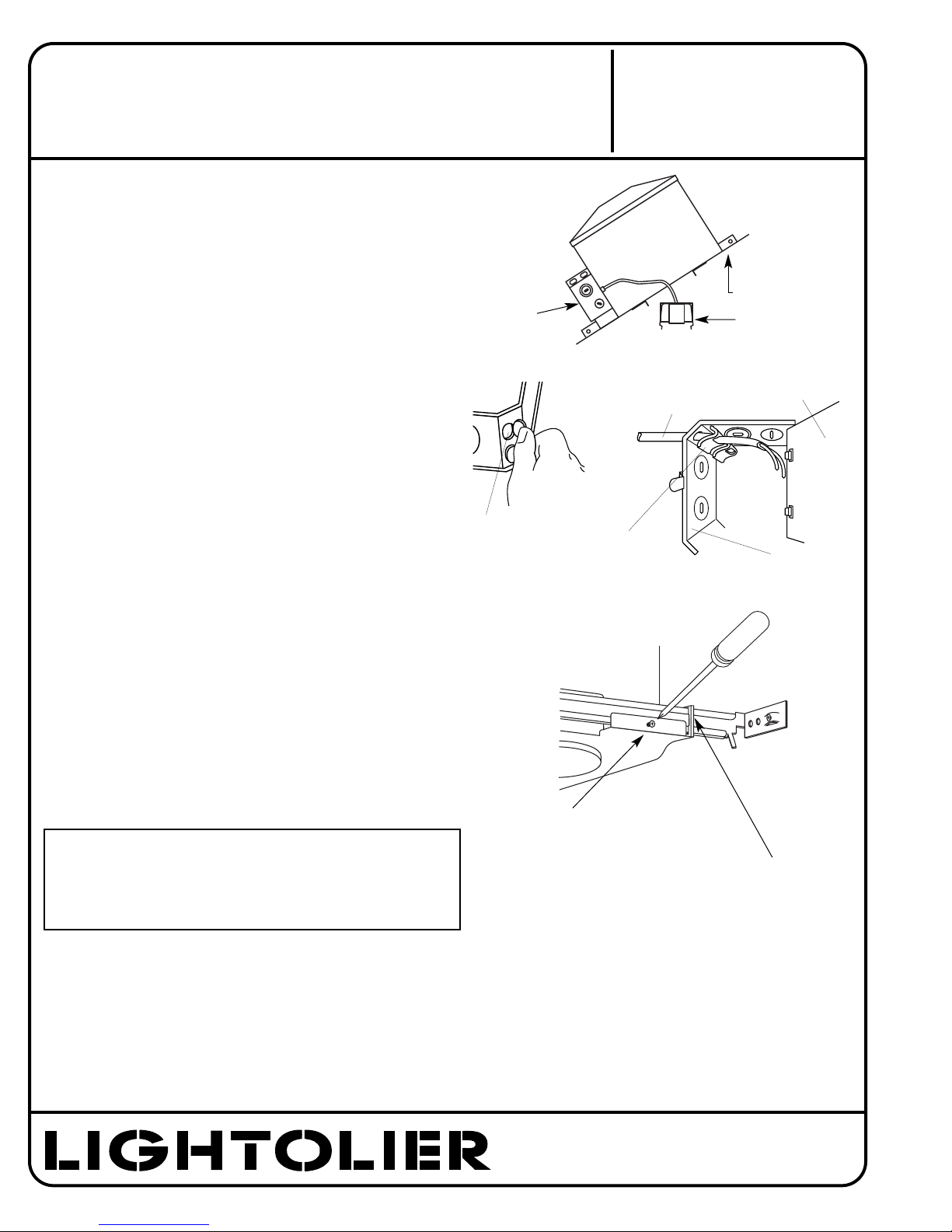
2. WIRE-IN (Fig. B)
Open hinged J-BOX COVER fully to its locked position (lift
slightly to unlock).
Open hinged KNOCK OUT to allow NON-METALLIC CABLE
to enter JUNCTION BOX. Push CABLE through CLAMP.
Note: Wiring and connections must not be placed in JUNCTION
BOX in a manner which will interfere with the CLAMPS
action to provide strain relief.
Wire to SUPPLY LEADS. WHITE FIXTURE LEAD to NEUTRAL
SUPPLY LEAD. BLACK FIXTURE LEAD to HOT (120V) SUPPLY
LEAD. BARE FIXTURE WIRE to SUPPLY GROUND. Use wirenuts
(local hardware item). Place all electrical connections in the
J-BOX and close the J-BOX COVER.
3. SWING-UP (Fig. C)
Extend MOUNTING BAR to reach opposite joist and fasten in
place. Adjust to desired position along MOUNTING BAR and
lock in place using LOCKING SCREW.
4. CLOSE-IN (Fig. D)
Install plasterboard or other dry type ceiling. Hole in board
can be cut either on the floor or after the board is secured to
the ceiling using MOUNTING FRAME opening as cutting guide.
Make sure ROTO-CLIPS are rotated out of hole area to be cut,
also making sure that socket and wiring are positioned away
from hole area.
Roto Clips can only be rotated counterclockwise.
This detail allows easy removal of reflector trim by rotating
TRIM counterclockwise and permits installing Reflector Trim
tightly against the ceiling surface by rotating trim clockwise
after pushing Trim into ceiling.
Note: When using 1116, 1117, 1117WH Trims, ceiling
thickness should be 3/4” maximum.
5.AIRSEAL®INSTALLATION (optional)
Install a bead of silicone caulking compound between the
ceiling opening and edge of HOUSING. Housings are tested in
accordance with ASTM E 283 (max 2 cfm @ 75 pa) and comply
with WSEC & MEC when installed as instructed.
6. SNAP-ON (Fig. E)
Important - Insert SOCKET CUP in neck
of REFLECTOR making sure SPRING TABS
fully engage into SLOTS in REFLECTOR.
7. PUSH-UP (Fig. F)
Push REFLECTOR TRIM straight up until
it is tight against ceiling.
SEE SEPARATE
REFLECTOR TRIM
INSTRUCTION
SHEETSÊ
}
HINGED KNOCK OUT
J-BOX COVER
NON-METALLIC
SHEATHED CABLE
(12 OR 14 GAUGE ONLY)
CABLE CLAMP
JUNCTION BOX
®
DEFORM MATERIAL AT
ANY CORNER OF FRAME
FOR ADDITIONAL LOCK
IF NEEDED
For sloped ceilings:
• For 1131 and 1133 series sloped ceiling trims, Mounting Frame
must be mounted with J-BOX on the “downhill” side. Mounting
Frame should be parallel to the joist.
MOUNTING BAR
J-BOX SOCKET CUP
LOCKING SCREW
INSTRUCTION SHEET NO.
IS:1104ICX
B1204 Page 2 of 2


