Grizzly T33679 User manual

For questions or help with this product contact Tech Support at (570) 546-9663 or techsupport@grizzly.com
MODEL T33679
ARTICULATING
LED LIGHT
INSTRUCTIONS
Introduction
The Model T33679 produces 3600 lumens and is
designed with three articulating joints and a swivel
base to provide an extensive range of movement.
It can be mounted to nearly any flat surface using
the L-bracket or clamping bracket.
Inventory
COPYRIGHT © MARCH, 2023 BY GRIZZLY INDUSTRIAL, INC.
NO PORTION OF THIS MANUAL MAY BE REPRODUCED IN ANY SHAPE
OR FORM WITHOUT THE WRITTEN APPROVAL OF GRIZZLY INDUSTRIAL, INC.
(FOR MODELS MFD. SINCE 03/23) #MN22628 PRINTED IN CHINA V1.03.23
***Keep for Future Reference***
To reduce risk of serious
injury, read this entire
manual BEFORE using
LED light. Read and
understand instructions/
safety warnings provided
by manufacturer for any
machine or tool you plan to
use with this light.
Figure 1. Model T33679.
Figure 2. Inventory.
A
B C D
E F
G H I
J K L
Contents (Figure 2) Qty
A. LED Light Assembly ................................... 1
—Base........................................................ 1
—Arm ......................................................... 1
—LED Light ................................................ 1
B. Clamping Bracket ....................................... 1
C. L-Bracket .................................................... 1
D. Crown Washers 8mm ................................. 4
E. Button Hd Cap Screws M8-1.25 x 50 ......... 2
F. Cap Screws M5-.8 x 16 .............................. 4
G. Fender Washers 8 x 30 x 0.6mm ............... 6
H. Flat Washers 5mm ..................................... 4
I. Lock Nuts M8-1.25 ..................................... 2
J. Hex Wrench 4mm ....................................... 1
K. Hex Wrench 5mm ....................................... 1
L. Open-End Wrench 13mm ........................... 1

-2- Model T33679 (Mfd. Since 3/23)
Assembly
To assemble light:
1. Position (1) 8 x 30 x 0.6mm fender washer
on each side of joint at lower end of LED arm
(see Figure 3).
2. Slide base arm connector over LED arm joint
(see Figure 3) so fender washers are cap-
tured and holes are aligned.
Note: Be sure side of base arm with power
cord faces nearest electrical outlet, and that
power cord does not interfere with machine
function.
3. Use (1) M8-1.25 x 50 button head cap screw,
(2) 8 x 30 x 0.6mm fender washers, (2) 8mm
crown washers, and (1) M8-1.25 lock nut to
secure joint components (see Figure 4).
Assembling the Model T33679 consists of secur-
ing the upper and middle articulating joints with
the supplied fasteners.
Figure 4. Joint components assembled.
Base
Arm
LED
Arm
Mounting with L-Bracket
Items Needed Qty
Mounting Fasteners ........................... As Needed
Pencil ................................................................. 1
Power Drill ......................................................... 1
Drill Bit ............................................................... 1
The L-bracket includes three mounting holes for
use with fasteners up to 1⁄4" diameter.
Wear safety glasses while
operating drill.
4. Press joint half at upper end of LED arm into
joint half on back of light (see Figure 5).
5. Use (1) M8-1.25 x 50 button head cap screw,
(2) 8 x 30 x 0.6mm fender washers, (2) 8mm
crown washers, and (1) M8-1.25 lock nut to
secure joint halves (see Figure 5).
Figure 5. Upper joint halves assembled.
Figure 3. Assembling joint components.
Base
Arm
LED
Arm
x2
To mount light with L-bracket:
1. Place L-bracket over intended mounting loca-
tion, and use a pencil to mark position of
holes to be drilled.

Model T33679 (Mfd. Since 3/23)-3-
Note: If L-bracket is positioned directly over
mounting surface (see Figure 6), allow mini-
mum 1⁄4"clearance between mounting sur-
face and L-bracket for cap screws and flat
washers to be installed in Step 4.
2. Drill holes at center of each marked position
according to size of fasteners to be used.
3. Position L-bracket over drilled holes and
secure with fasteners.
Figure 8. LED light mounted on L-bracket.
x 4
Mounting with Clamping Bracket
Loosen the clamp handle until the mouth of the
clamp will slide onto the mounting surface. Tighten
the clamp handle until the clamp is secure, then
mount the light on the clamp using (4) M5-.8 x 16
cap screws and 5mm flat washers (see Figure 9).
Figure 9. LED light mounted on clamping
bracket.
x 4
Clamp
Clamp
Handle
4. Attach base of LED light to L-bracket with (4)
M5-.8 x 16 cap screws and 5mm flat washers
(see Figure 8).
Figure 6. Example of L-bracket positioned over
mounting surface.
Minimum 1⁄4"
Clearance Mounting Holes
L-Bracket
Figure 7. Example of L-bracket positioned away
from mounting surface.
Mounting Holes
L-Bracket

-4- Model T33679 (Mfd. Since 3/23)
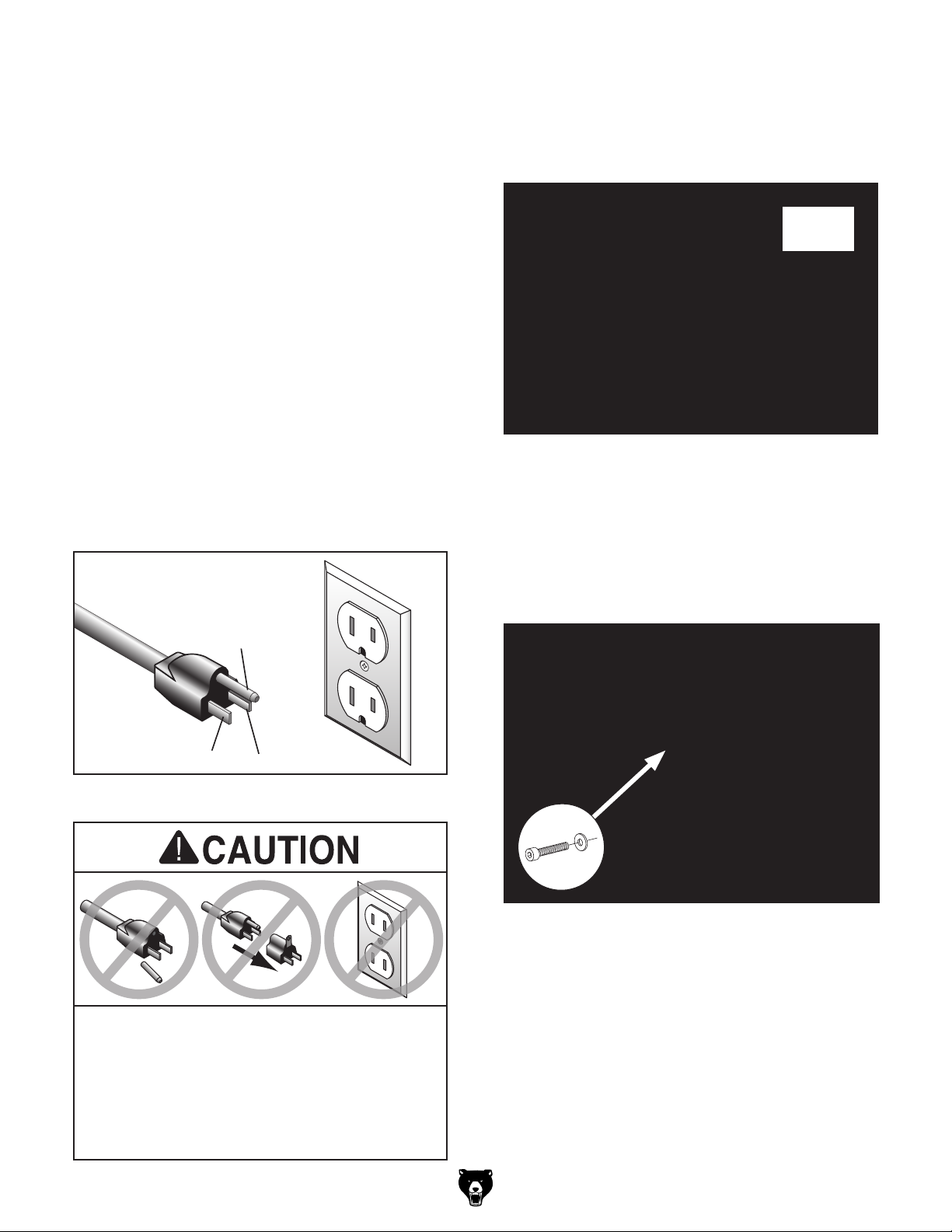
Figure 10. Typical 5-15 plug and receptacle.
Grounding Pin
Neutral Hot
5-15 PLUG
GROUNDED
5-15 RECEPTACLE
SHOCK HAZARD!
Two-prong outlets do not meet the grounding
requirements for this tool. Do not modify or
use an adapter on the plug provided—if
it will not fit the outlet, have a qualified
electrician install the proper outlet with a
verified ground.
This tool is equipped with a power cord that has
an equipment-grounding wire and a grounding
plug. Only insert plug into a matching receptacle
(outlet) that is properly installed and grounded in
accordance with all local codes and ordinances.
DO NOT modify the provided plug!
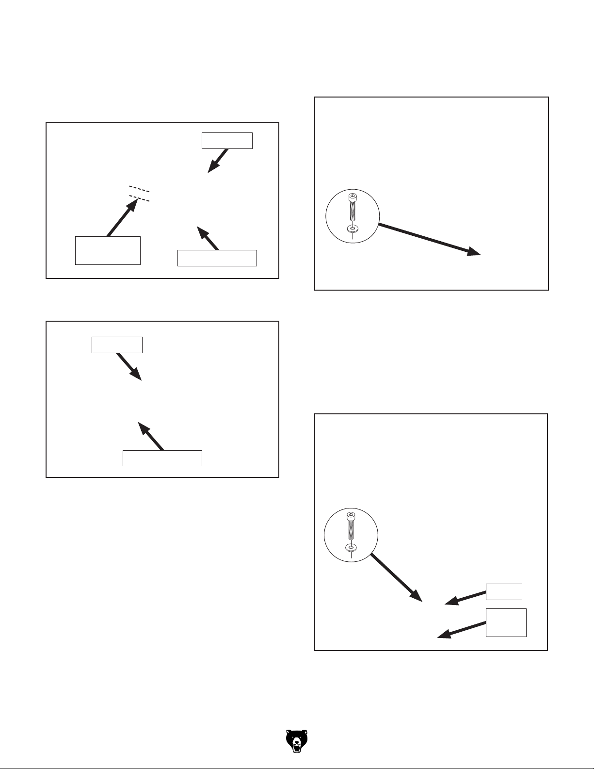
Apply light pressure at each of the articulating
joints to manuever the light to the desired position.
To rotate the light from side to side, loosen the
cap screws shown in Figure 12, rotate the light
to the desired position, then tighten the screws to
secure.
Figure 12. Location of cap screws in base.
x 2
Operation
Press the ON/OFF button shown in Figure 11
once to turn the LED light ON; press the button
again to turn the light OFF.
Figure 11. Location of ON/OFF button.
ON/OFF
Button
Grounding & Plug Requirements
120V Circuit Requirements
Nominal Voltage .................... 110V, 115V, 120V
Cycle ..........................................................60 Hz
Phase ........................................... Single-Phase
Power Supply Circuit ......................... 15 Amps
Plug/Receptacle ............................. NEMA 5-15
This tool is prewired to operate on a power supply
circuit that has a verified ground and meets the
following requirements:
This tool MUST be grounded. In the event of
certain malfunctions or breakdowns, grounding
reduces the risk of electric shock by providing a
path of least resistance for electric current.
Other Grizzly Lighting Equipment manuals