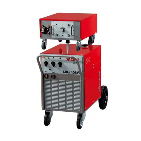
JESS WELDING E4-2800 PULS RMT User manual

Operating manual
Inverter Welding Power Source
for MIG/MAG - Processes
E4 –2800/4200/5200 PULS RMT
M4 –3000/4000/5500 RMT
Cooling Unit K4

Recommendation:
Please keep this operating instruction manual easily accessible for all
welders and service staff. Read the brochure carefully and follow exactly
the instructions given in order to prevent any malfunctions and operating
errors.
In the PDF version of this manual, hyperlinks for easy navigation through the document
are included. Clickable hyperlinks are shown in dark blue and the mouse pointer
changes. Hyperlinks will change to a position in the document that provides further
context information. Change back to the original text position in the document via the
"Back" - button of your PDF viewer program.
Subject to technical and / or optical changes.
Any kind of reproduction, in whole or in part, as well as processing or
distribution using electronic systems requires the written permission of
company Jäckle & Ess System GmbH.
Jäckle & Ess System GmbH
Riedweg 4 u. 9
D – 88339 Bad Waldsee
Tel.: +49-7524-9700
Fax: +49-7524-9700-30
http://www.jess-welding.com
info@jess-welding.com

04/2014
Operating Manual E4-2800/4200/5200 / M4-3000/4000/5500
Page 1
1INTRODUCTION .............................................................................................................3
1.1 Preface.................................................................................................................... 3
1.2 Product description ................................................................................................. 3
1.3 ESS Service network ............................................................................................... 3
2SAFETY INSTRUCTIONS ...............................................................................................4
2.1 General Information................................................................................................. 4
2.2 Transport ................................................................................................................. 4
2.3 Installing and environmental conditions ................................................................... 4
2.4 Personal protection ................................................................................................. 4
2.5 Elektromagnetic Compatibility (EMC) ...................................................................... 6
3MAINTENANCE ..............................................................................................................8
4TECHNICAL DATA ....................................................................................................... 10
4.1 Technical Data Welding Power Source ..................................................................10
4.2 Technical data cooling unit K4 ................................................................................12
4.3 Technical data undercarriage FW 4 ........................................................................12
5MACHINE DESCRIPTION ............................................................................................ 13
5.1 Front view ..............................................................................................................13
5.2 Rear view ...............................................................................................................14
5.3 Wire feed unit .........................................................................................................15
5.4 Connection for Push-Pull welding torch and for potentiometer-control (Option) ......16
6OPERATING ELEMENTS FOR MACHINE CONTROL ................................................. 17
6.1 Operating concept ..................................................................................................17
6.2 Control panel version UNO – Overview ..................................................................18
6.3 Control panel – details ............................................................................................19
6.4 Potentiometer control (Option) ...............................................................................32
7COMMISSIONING ........................................................................................................ 33
7.1 General Instructions ...............................................................................................33
7.2 Utilisation for intended purposes only .....................................................................33
7.3 Installation requirements ........................................................................................33
7.4 Mains connection ...................................................................................................33
7.5 Cooling of the machine – Cooling set K4 ................................................................34
7.6 Equipment for MIG/MAG welding and MIG brazing ................................................35
8WELDING PROCEDURES ........................................................................................... 39
8.1 Possible processes ................................................................................................39
8.2 General description of the individual methods ........................................................39
8.3 MIG/MAG - normal welding and brazing .................................................................41
8.4 MIG/MAG Synergic – Normal welding and brazing .................................................42
8.5 Pulsed welding and brazing (only E4-2800/4200/5200) ..........................................43

Page 2
Operating Manual E4-2800/4200/5200 / M4-3000/4000/5500
04/2014
8.6 Power Pulse ...........................................................................................................44
8.7 RMT- procedure .....................................................................................................45
8.8 MMA - welding .......................................................................................................46
9PARAMETER LISTS ..................................................................................................... 47
9.1 List of special characteristics – User template ........................................................47
9.2 Job list - User template ...........................................................................................48
10 PROBLEMS DURING OPERATION.............................................................................. 50
10.1 General ...............................................................................................................50
10.2 List of error messages ........................................................................................51
10.3 List of Warnings ..................................................................................................52
11 CIRCUIT DIAGRAMS AND LEGENDS ......................................................................... 53
11.1 Circuit diagram E4–2800/4200/5200, M4-3000/4000/5500 .................................53
11.2 Legend to circuit diagram E4–2800/4200/5200, M4-3000/4000/5500 - part 1 .....60
11.3 Circuit diagram cooling set K4 ............................................................................62
11.4 Legend to circuit diagram cooling set K4 ............................................................63
12 SPARE PARTS LIST E4 – 2800/4200/5200, M4-3000/4000/5500, COOLING SET K4 . 64
13 Remote Control RC Multi ............................................................................................... 66
13.1 Technical data remote control RC Multi ..............................................................66
13.2 Description front view .........................................................................................66
13.3 Remote control RC Multi - overview ....................................................................67
13.4 Energy value .......................................................................................................68
13.5 Correction value .................................................................................................69
13.6 Job - functions ....................................................................................................70
13.7 Power Pulse functions ........................................................................................70
13.8 HC MAG functions ..............................................................................................71
14 ABBREVIATIONS ......................................................................................................... 73

04/2014
Operating Manual E4-2800/4200/5200 / M4-3000/4000/5500
Page 3
1 INTRODUCTION
1.1 Preface
You have chosen a quality product of Jäckle & Ess System GmbH. Thank you for your trust!
For more than 50 years, Jäckle & Ess units are characterized by a high quality standard and
reliability. Long service life, even under the harshest conditions, is standard for all Jäckle &
Ess products. As usual, ESS welding units are easily understandable in maintenance and
use, in order to help your productivity needs perfectly.
Before initial use, please carefully read these instructions. It helps to convey a better
understanding and safe operation of the unit. For sure, you might discover one or the other
new feature that helps you control your processes easier. Please also observe the safety
instructions in chapter 2.
We wish you much pleasure with your new Jäckle & Ess welding unit!
1.2 Product description
The MIG/MAG pulse inverter welding power source E4-2800 is based on a new power supply
with extremely fast dynamics and digital control.
All the tools are opportunities for individual programming.
1.3 Jäckle & Ess Service network
Even a quality product requires replacement parts or service after a certain time of use. We
provide the correct parts quickly and reliably.
Our after-sales service department – with its highly trained staff – will be pleased to assist you
in all service matters.

Page 4
Operating Manual E4-2800/4200/5200 / M4-3000/4000/5500
04/2014
2 SAFETY INSTRUCTIONS
2.1 General Information
The welding machine is constructed according to EN 60974-1.
The unit may involve dangers, however, unless
• It is operated by qualified or at least trained personnel
• It is used in accordance with the “intended purpose“
• Damage to equipment or accessories are repaired immediately´
The device is not suitable for thawing frozen pipelines – Danger of Fire!
The legal safety rules must be observed.
2.2 Transport
The units should always be transported without gas bottle. Prior to transport, all the cables
have to be wound up and bound together on the device.
The unit can be moved on its wheels in combination with cooling unit and wheel set.
Carrying handles, if available, must not be used for transport by crane! A suitable carrying
device has to be used!
2.3 Installing and environmental conditions
The device must not be operated in hazardous areas.
The environment must be free from excessive dust, unusual mechanical stresses (vibrations,
shocks) and aggressive media, unless they occur during welding.
The device should be placed on a flat, horizontal ground. If it has to be placed on an inclined
plane or on a higher working place, machine and the gas bottle must be adequately secured.
Inlet and exhaust air must be free. Cooling air inlet and outlet openings must not be covered
by welding aprons, towels, walls, etc.
Setting up the device in direct rain, the device must be covered at a large scale. However,
the cooling air flow must not be affected!
2.4 Personal protection
Arc Rays
The emission of UV rays from the welding arc may cause injuries of the eyes and
combustion of the skin. Therefore, the welder must wear dry protective clothing (gloves,
helmet, protective mask, ...) and should not wear contact lenses.
Protect other persons in the vicinity of the welding area from UV rays and spatter by suitable,
non-flammable partition walls, safety glasses or something similar.

04/2014
Operating Manual E4-2800/4200/5200 / M4-3000/4000/5500
Page 5
Smoke and gases
Harmful metallic powder and smoke are released during welding. Ensure sufficient supply of
fresh air and adequate ventilation. Never use oxygen for the ventilation of rooms.
The following metals and alloys or workpieces that are coated with them require a suction
device during welding: beryllium, lead, chrome, graphite, cadmium, mercury or zinc.
To prevent the formation of toxic gases during welding, the workpiece has to be cleaned from
any residues of halogen solvents and degreasing agents.
It is strongly recommended, not to place gas cylinders into narrow places. In case of leaks,
shielding gas may escape to such an extent that the oxygen content of the inhaled air
decreases to dangerously low values.
Flammable gases or gases which induce a chemical reaction, such as Acetylene, Propane,
pure Hydrogen, pure Oxygen are prohibited!
Fire prevention
Any kind of fire hazards must be avoided. Flames can form from flying sparks, spatters,
glowing parts or hot slag.
Never weld on containers with flammable or toxic contents. Remove any kind of flammable
material from the welding area. Do not weld in areas where flammable vapours or gases can
develop.
Ensure that fire extinguishing equipment – appropriate to the welding process – is available
close to the welding area and that easy access is possible.
Explosion
Never weld on or in the vicinity of containers which are under pressure, and do not weld in
rooms with a high concentration of explosive powders, gases or vapours.
High-pressure gas cylinders have to be handled with utmost care:
• The gas cylinder must not be connected directly to the gas hose of the welding power
source. A pressure regulator has to be interposed
• Protect gas cylinder, valves, pressure regulator and gas hose from heating, damage
and violence.
Electrical danger
The terminal voltage of the welding machine may be up to 113V= or 48 V~ !
• If you have to stand on metal or in a wet area during welding, insulation with
suitable dry material is required.
• Avoid contact with wet or conductive metal parts; wear dry clothing. Keep
everything dry, including clothing, welding area, cables and welding machine.
• Although the machine is marked „S“ (approved for welding in environments with
increased electrical hazard), the power source itself may not be installed here,
because of the mains voltage 230 V or 400 V. Only the welding torch and the wire
drive unit are permitted at such places.
• Always maintain correct insulation of cables, plugs and welding torches. Before any
work is carried out inside the power source, the mains switch must be switched off
and the mains plug has to be disconnected.

Page 6
Operating Manual E4-2800/4200/5200 / M4-3000/4000/5500
04/2014
• Repairs and modifications may only be carried out by authorized, trained specialist
personnel.
• Welding units may only be used if all covers are present and correctly installed.
• Before moving the machine, pull out the mains plug. Do not operate with portable
welding units while putting them around the shoulders with the carrying strap.
• Switch off the welding unit when not in use and close the reducing valve of the gas
cylinder.
Pacemakers
The functioning of heart pacemakers can be adversely affected by electromagnetic fields of
power circuits. Users of such devices should consult their doctors before going anywhere
near a welding or cutting workplace.
2.5 Elektromagnetic Compatibility (EMC)
General information
This welding device complies with the standard regulations of the EMC directive EN 60974-
10. According to CISPR11 it is a Class A equipment for use in the industrial sector. In other
areas an electromagnetic compatibility is not assured.
The user is responsible for the installation and operation of the welding machine according
to the manufacturer’s instructions. If there is electromagnetic interference, the operator is
responsible for finding a solution, with the technical assistance of the manufacturer of the
welding machine. In order to reduce electromagnetic interference to a minimum, especially
in residential environments, additional safety precautions may be necessary.
Evaluation of the area
The following equipment and facilities may be subject to electromagnetic interference:
• Mains supply lines, control lines, signal and telecommunication lines
• Radio and TV broadcasting station and receiver
• Computer and other control units
• Safety devices, e.g. alarm systems
• Heart pacemakers and hearing aids
• Units for calibration or measurement
• Units with little immunity from interference
The extent of the surrounding area to be considered depends on the construction of the
building and other activities which take place there and may exceed the boundaries of the
property.

04/2014
Operating Manual E4-2800/4200/5200 / M4-3000/4000/5500
Page 7
Procedure to reduce emissions
• Mains supply:
Installation of additional mains filters, screening of mains supply lead.
• Housing:
All cover plates must be completely assembled.
• Welding cables:
Should be as short as possible and should run close together on or near to the
floor.
• Potential equalization:
The electric connection of all metal parts in and near a welding machine should be
taken into account.
• Earth connection of workpiece:
If the workpiece is not put to earth for reasons of electrical safety or because of its
size and position (e.g. shipbuilding), a connection of the workpiece may reduce
emissions in certain cases. It must be ensured, however, that earthing of the
workpiece does not increase the risk of accident to the user or causes damage to
other electrical equipment. In this case, connection can be effected by means of
capacitors.
• Screening:
Selective screening of other cables and equipment in the vicinity may reduce
electrical interference. Screening of the complete welding equipment may be
considered in special situations.

Page 8
Operating Manual E4-2800/4200/5200 / M4-3000/4000/5500
04/2014
3 MAINTENANCE
Warning!
Dangers of electricity!
Before any work is carried out inside the power source, the machine must
be switched off and the mains plug disconnected.
After disconnecting the mains plug, wait at least three minutes, until the
capacitors have discharged and reached safe values!
Regular maintenance of the machine is essential for safe and trouble free operation.
Maintenance of wearing parts in short regular intervals:
• The life of gas nozzles and current tips, which are subject to wear, can be extended
considerably when they are sprayed from time to time with torch spray, which allows
easier removal of spatter or prevents their adhesion altogether.
• The current tips must be cleaned with a cleaning drill after welding one wire coil
(15 kg).
• The liners must be cleaned after welding 50 – 100 kg wire, depending on the wire
size. To do this, they are pulled out of the outer hose. Then, outer hose and liners
are blown out with dry and clean compressed air.
Daily Checks:
• Check the machine for abnormal vibration, humming noise and smell.
• Check connecting sockets, cables, hoses and torch for abnormal heating, insulation
faults and cleanness.
• Check the wire drive unit. Welding wire abrasion must be removed by using dry
compressed air, which also prevents premature wear.
• The mechanical drive parts must be cleaned at regular intervals.
Tests to ensure electrical safety:
The rule EN 60974-4 „Periodic inspection and testing of arc welding equipment“ specifies test
methods for the inspection during operation.
Caution: Tests must only be carried out by an expert in the field of electrical repair, preferably
also familiar with welding and allied processes.

04/2014
Operating Manual E4-2800/4200/5200 / M4-3000/4000/5500
Page 9
Periodic inspection according to EN 60974-4
This regulation does not lay down test intervals since this mainly depends on the degree of
utilisation and the mechanical stress (such as use on construction sites).
Test / activities
According to
EN 60974-4
Recommendation
Test interval
Depending of the degree
of utilisation, at least
annually
Cleaning
X
X
Visual inspection
X
X
Electrical test – measurement of:
- Open-circuit voltage
X
X
- Insulation resistance
X
X
- Protective conductor resistance
X
X
- Primary leakage current
- Secondary leakage current
Alternative to
insulation resistance
X
Functional test
X
Test report + label *
X
X
* Tests have to be documented in a test report and a test label has to be attached to the
welding equipment to indicate that it has passed the test. The label shall state the date of
testing.

Page 10
Operating Manual E4-2800/4200/5200 / M4-3000/4000/5500
04/2014
4 TECHNICAL DATA
4.1 Technical Data Welding Power Source
Type:
E4-2800 / M4-3000
Input:
Line voltage
3/PE AC 400 V
Nominal frequency
50 – 60 Hz
Tolerance line input
-20 % / + 25 %
Primary current max / effective
16 / 11 A
Input constant power
11 kVA
Mains fuse protection, slow
16 A
Power supply cable
4 x 2,5 mm2
Output:
Max. open-circuit voltage
70 V
Current range MIG/MAG / MMA
5 – 270 A / 5 – 250 A
Welding current at 40 % ED (40°C) - MIG/MAG / MMA
270 A / 250 A
Welding current at 60 % ED (40°C) - MIG/MAG / MMA
230 A / 210 A
Welding current at 100 % ED (40°C)- MIG/MAG / MMA
200 A / 180 A
Type of protection
IP 23 S
Type of cooling
AF
Dimensions air cooled, with rubber feet L x W x H
700 x 350 x 420 mm
Dimensions air cooled, with wheels (undercarriage FW4)
L x W x H
1000 x 500 x 620 mm
Dimensions water cooled, with rubber feet L x W x H
700 x 350 x 660 mm
Dimensions water cooled, with wheels (undercarriage FW4)
L x W x H
1000 x 500 x 860 mm
Weight air cooled, with rubber feet
45 kg
Weight air cooled, with wheels (undercarriage FW4)
61 kg
Weight water cooled, with rubber feet
69 kg
Weight water cooled, with wheels (undercarriage FW4)
85 kg
Noise level
70 dB (A) on idling
Admission
S-symbol *
According to EN
60 974-1
* [S]-symbol: Admitted for welding under conditions of increased electrical hazard
according to EN 60974-1.
A working place related emission factor during welding cannot be indicated since
this depends on welding procedure and environmental conditions.

04/2014
Operating Manual E4-2800/4200/5200 / M4-3000/4000/5500
Page 11
Type:
E4-4200 / M4-4000
E4–5200 / M4-5500
Input:
Line voltage
3/PE AC 400 V
3/PE AC 400 V
Nominal frequency
50 – 60 Hz
50 – 60 Hz
Tolerance line input
-20 % / + 25 %
-20 % / + 25 %
Primary current max / effective
25 / 16 A
38 / 31 A
Input constant power
17 kVA
26 kVA
Mains fuse protection, slow
16 A
32 A
Power supply cable
4 x 2,5 mm2
4 x 4,0 mm2
Output:
Max. open-circuit voltage
70 V
70 V
Current range MIG/MAG / MMA
5–400 A / 5–350 A
5–520 A / 5–500 A
Welding current at 40 % ED (40°C) - MIG/MAG / MMA
400 A / 350 A
520 A / 500 A
Welding current at 60 % ED (40°C) - MIG/MAG / MMA
360 A / 320 A
500 A / 480 A
Welding current at 100 % ED (40°C)- MIG/MAG / MMA
310 A / 280 A
450 A / 420 A
Type of protection
IP 23 S
IP 23 S
Type of cooling
AF
AF
Dimensions air cooled, with rubber feet L x W x H
700 x 350 x 660 mm
700 x 350 x 660 mm
Dimensions water cooled, with wheels
(undercarriage FW4) L x W x H
1000 x 500 x 1100 mm
Weight air cooled, with rubber feet
70 kg
82 kg
Weight water cooled, with wheels (undercarriage FW4)
110 kg
122 kg
Noise level
70 dB (A) on idling
70 dB (A) on idling
Admission
S-symbol *
S-symbol *
According to EN
60 974-1
60 974-1
* [S]-symbol: Admitted for welding under conditions of increased electrical hazard
according to EN 60974-1.
A working place related emission factor during welding cannot be indicated since
this depends on welding procedure and environmental conditions.

Page 12
Operating Manual E4-2800/4200/5200 / M4-3000/4000/5500
04/2014
4.2 Technical data cooling unit K4
Cooling unit
K4
Line voltage
3/PE AC 400 V
Nominal frequency
50 Hz
Mains fuse protection
16 A
Max. cooling capacity
800 W
Max. pressure
4,0 bar
Type of protection
IP 23
Type of cooling
AF
Dimensions L x W x H
700 x 350 x 240 mm
Weight
24 kg
According to EN
60 974-2
4.3 Technical data undercarriage FW 4
Undercarriage
FW 4
Dimensions L x W x H
1000 x 500 x 200 mm
Weight
16 kg

04/2014
Operating Manual E4-2800/4200/5200 / M4-3000/4000/5500
Page 13
5 MACHINE DESCRIPTION
5.1 Front view
Fig. 5-1
Pos.
Description
1
Torch cooling
2
Central connector for the
welding torch
3
CAN-connector for remote control /
welding torch
4
Control panel welding power
source
1
2
3
4

Page 14
Operating Manual E4-2800/4200/5200 / M4-3000/4000/5500
04/2014
5.2 Rear view
Fig. 5-2
Pos.
Description
5
Power ON / OFF
6
Key gas test
7
Shield gas connection G ¼“
8
Bracket for gas cylinder
with straps to secure
9
Workpiece connection minus pole
10
Plus pole connection
11
Fill opening for coolant
12
Button for water pump test / filling
13
Power supply
5
8
9
11
6
10
12
13
7

04/2014
Operating Manual E4-2800/4200/5200 / M4-3000/4000/5500
Page 15
5.3 Wire feed unit
Fig. 5-3
Pos.
Description
14
Mandrel for wire coil with
brake and safety catch
15
Clamping lever for
contact pressure of
wire feed rollers
16
Pushbutton for wire
inching
15
14
16

Page 16
Operating Manual E4-2800/4200/5200 / M4-3000/4000/5500
04/2014
5.4 Connection for Push-Pull welding torch and for potentiometer-control
(Option)
Fig. 5-4
Pos.
Description
17
Connector socket
Connection via flange socket with the following assignment:
A
Negative connection (left stop) for both potentiometers
B
Bridge to „C“ for detection „potentiometers available“
C
+ 24V, supplied internally. Do not apply voltage!
D
Torch key to +24V = „C“, optional
E
Poti 1 = ‚Energy’, center tap. Use this one if only one potentiometer is available
F
Poti 2 = ‚Arc Length / Voltage’, center tap
G
Positive connection (right stop) both potentiometers
H
- free -
I
Positive connection Push-Pull motor
J
Negative connection Push-Pull motor
17

04/2014
Operating Manual E4-2800/4200/5200 / M4-3000/4000/5500
Page 17
6 OPERATING ELEMENTS FOR MACHINE CONTROL
6.1 Operating concept
Jäckle & Ess MIG/MAG Inverter welding power sources can be operated with different
operating concepts:
• Operation via welding unit (front panel FLKC (UNO)
• Operation by remote control with all functions / sub-functions

Page 18
Operating Manual E4-2800/4200/5200 / M4-3000/4000/5500
04/2014
6.2 Control panel version UNO – Overview
Compact control unit – also available as a remote control
Fig. 6-1
Section
Description
Selection of welding procedure
Selection of characteristic curves for pulsed arc, RMT and short arc
+
Display for special characteristics / system failure messages
Control panel „Comfort“ for selection of additional parameters
Job administration
LED indicator for system failure
Operating modes
Adjustment of wire feed speed / energy
Adjustment procedure Norm: Voltage
Adjustment procedure Synergic / Pulse: Arc length correction
The individual functions are selected or adjusted by a short pressure on the
associated grey buttons or via the rotary push buttons. The status-LED next
to the symbols indicate the current settings. These settings are stored at
power off.
1
2
3
5
9
1
8
4
2
3
5
4
7
8
9
7
This manual suits for next models
5
Table of contents
Other JESS WELDING Welding System manuals

JESS WELDING
JESS WELDING conMIG 300 User manual

JESS WELDING
JESS WELDING MIG 325 User manual

JESS WELDING
JESS WELDING Power Plasma 2 User manual

JESS WELDING
JESS WELDING G450 S User manual

JESS WELDING
JESS WELDING MIG 296 User manual

JESS WELDING
JESS WELDING WIG 165i User manual

JESS WELDING
JESS WELDING inoMIG 350 User manual
Popular Welding System manuals by other brands

Migatronic
Migatronic OMEGA2 CoWelder 300 user guide

Rothenberger
Rothenberger ROREC Pro Digital Instructions for use

IO Thrifty
IO Thrifty TC-WELDER user guide

Miller
Miller SQUAREWAVE 1000 owner's manual

Bernard
Bernard Q and S Series QS234X-1.1 Specification sheet

ESAB
ESAB Aristo MechTig 3000i instruction manual