5
Assembly Instructions
Note: Some parts may come pre-installed. Refer
to parts breakdown for numbers found in
parentheses (#). Figure 1 shows provided
fasteners.
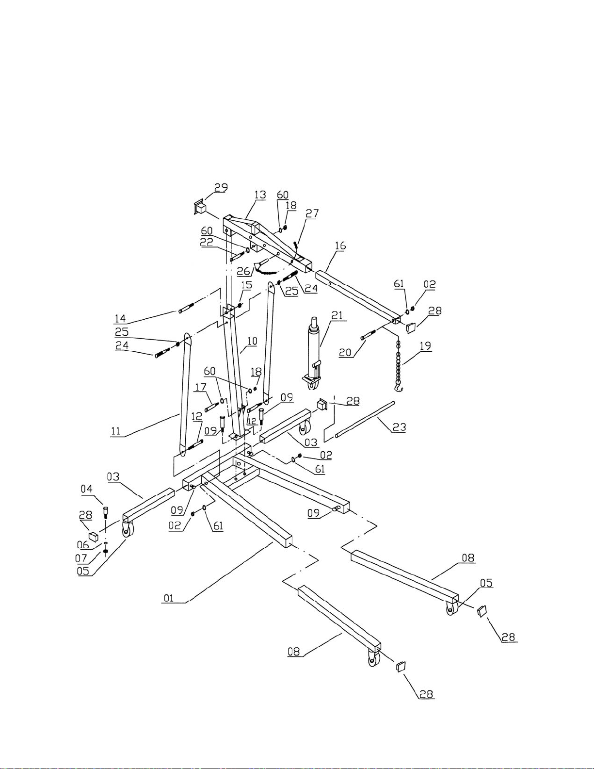
Figure 1
1. Install a caster assembly (05) to each short
extension leg (03) with M8x20 screws (04), M8
lock washers (06) and M8 hex nuts (07).
2. Slide short extension legs (03) into the rear
support of base (01). Insert two M12x25
screws (09) into threaded holes and tighten to
hold legs in place.
3. Install a caster assembly (05) on each long
extension leg (08) with M8x20 screws (04), M8
lock washers (06) and M8 hex nuts (07).
4. Slide long extension legs (08) into front
supports of base (01). Insert two M12x25
screws (09) into threaded holes and tighten to
hold legs in place.
5. Connect post (10) to base (01) with two
M12x25 screws (09) and two M12 washers
(61) into the threaded holes. Do not fully
tighten yet.
6. Attach supports (11) to base (01) and top of
post (10) using two M12x100 screws and two
M12 nuts (15) at the bottom. At the top of the
supports, install washers (25) and handles
(24). Tighten the handles using a wrench on
the flats.
7. Tighten the lower screws on the supports (11)
and the post (01).
8. Connect boom (13) to post (10) using one
M20x125 screw (14), one M20 nut (15), and
two M20 washers (60).
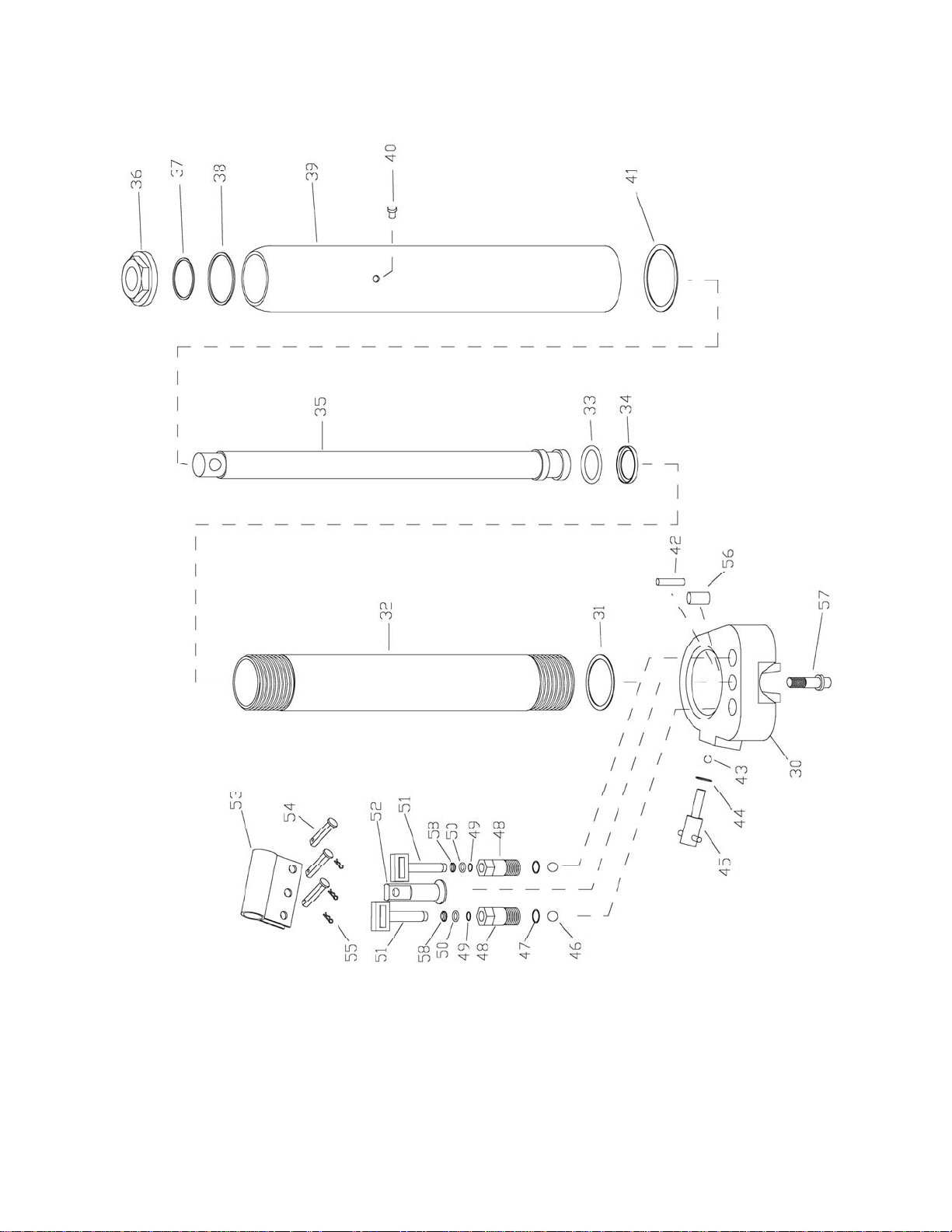
9. Bolt lower portion of ram (21) to post (10)
using one M16x100 screw (17), one M16 nut
(18), and two M16 washers (60).
10. Bolt upper portion of ram (21) to boom (13)
using one M16x75 screw (22), one M16 nut
(18), and two M16 washers (60).
11. Slide boom extension (16) into boom (13).
Insert adjustment pin (26) through one of the
holes and secure with hitch pin (27).
12. Install chain and load hook using M12x80
screw (20), M12 hex nut (02) and M12 washer
(61).
13. Insert small covers (28) into short extension
legs (03), long extension legs (08), and boom
extension (16). Insert big cover (29) into back
end of boom (13).
14. The pump handle (23) can be stored in the
holder on the post (10) when not in use.
Operation
1. Load to be lifted must be securely attached
with slings or chain of adequate size and
strength. Before lifting the load, be sure load
cannot twist, or fall from attachment.
2. Move crane into position. Legs must be
extended out beyond the boom extension.
3. Close hydraulic valve at base of ram by
inserting groove of pump handle onto release
valve (45), and turning clockwise until tight.
4. Place slings or chains in center of hook and
make sure safety latch is securely latched.
5. Slowly raise load to desired height by inserting
handle into ram and pumping handle. Be
careful to observe if the load wants to shift,
and prevent load from rotating or swinging.
6. Move load to desired location by rolling crane
assembly. Use caution so that load does not
swing or rotate.
7. Carefully lower load to desired location by
inserting ram handle onto release valve (45) at
base of ram, and slowly turning counter-
clockwise. Do not lower too quickly, and
confirm load is secure once lowered fully.