Main Body Assembly
Index Part
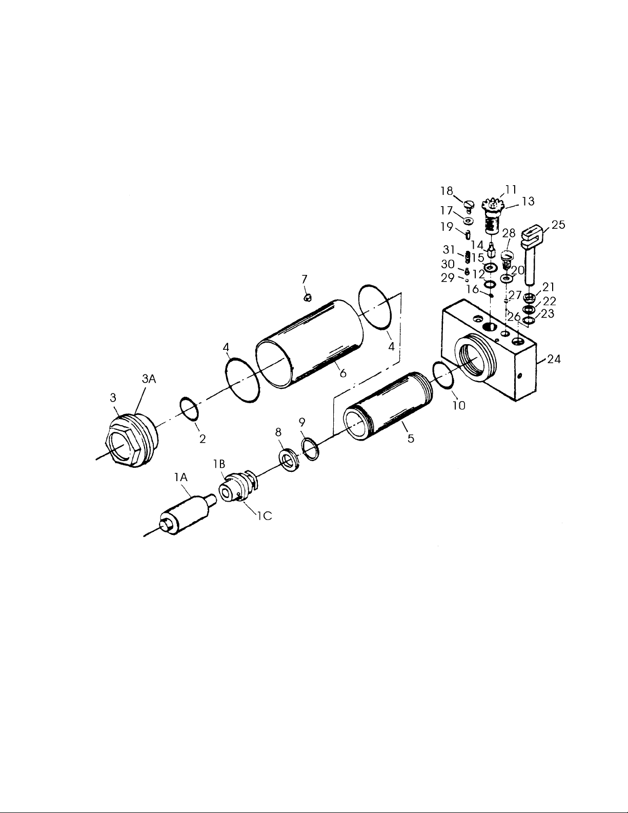
No. No. Description Qty.
1.......... 00400.................................Side Plate.................................................................................2
2.......... 00500.................................Caster Assembly * ...................................................................2
3.......... 00816.................................Lock Nut ...................................................................................2
4.......... 00012.................................Wheel * ....................................................................................2
5.......... 00801.................................Washer .....................................................................................2
6.......... 00802.................................Retaining Ring * ......................................................................2
7.......... 00300.................................Power Unit Assembly...............................................................1
8.......... 00803.................................Screw .......................................................................................2
9.......... 00804.................................Lock Washer ............................................................................2
10........ 00803.................................Linkage Assembly....................................................................1
11........ 00007.................................Shaft Arm .................................................................................1
12........ 00013.................................Saddle * ...................................................................................1
13........ 00805.................................Grease Fitting...........................................................................1
14........ 00008.................................Bolt Link ...................................................................................2
15........ 00806.................................Retaining Ring..........................................................................1
16........ 00600.................................Ram..........................................................................................1
17........ 00807.................................Pin ............................................................................................1
18........ 00005.................................Return Spring * ........................................................................1
19........ 00808.................................Retaining Ring..........................................................................2
20........ 00809.................................Lock Washer ............................................................................2
21........ 00810.................................Hex Nut ....................................................................................2
22........ 00811.................................Lock Washer ............................................................................2
23........ 00006.................................Bolt ...........................................................................................2
24........ 00004.................................Torsion Spring * ......................................................................1
25........ 000812...............................Release Valve Assembly .........................................................1
26........ 00002.................................Plunger Pin...............................................................................1
27........ 00208.................................Gear Shaft................................................................................1
28........ 00813.................................Pin ............................................................................................1
29........ 00700.................................Lifting Arm Assembly ...............................................................1
30........ 00209.................................Release Valve Gear * ............................................................1
31........ 00814.................................Lock Washer ............................................................................1
32........ 00815.................................Hex Nut ....................................................................................1
33........ 00204.................................Handle Bolt...............................................................................1
34........ 00205.................................Spacer......................................................................................1
35........ 00100.................................Handle (lower) * ......................................................................1
36........ 00001.................................Handle (upper) * ......................................................................1
37........ 00817.................................Screw * ....................................................................................1
38........ 00200.................................Handle Socket..........................................................................1
* indicates normal stocked part. Other parts may be purchased on a special order basis only.
Contact JET Equipment & Tools (1-800-274-6848) for details.