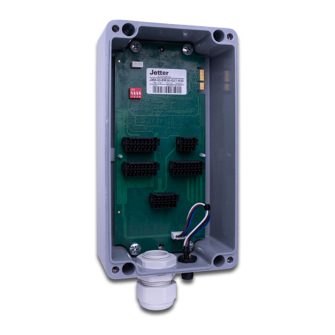
Jetter JXM-IO-E32 User manual

User Manual
JXM-IO-E32
Expansion Module
We automate your success.
60885294_00

Jetter AG
Graeterstrasse 2
71642 Ludwigsburg
Germany
Phone
Switchboard +49 7141 2550-0
Sales +49 7141 2550-531
Technical Hotline +49 7141 2550-444
E-mail
Technical Hotline [email protected]
Sales [email protected]
Translation of the original User Manual
Revision 1.00.1
Date of issue 5/4/2021
This document has been compiled by Jetter AG with due diligence, and based on the known
state of the art. Revisions and further development of our products are not automatically
mentioned in a reviewed document. Jetter AG shall not be liable for errors in form or content,
or for missing updates, as well as for damages or disadvantages resulting from such failure.

Jetter AG Table of contents
JXM-IO-E32 User Manual iii
Table of contents
1 Introduction ......................................................................................................................................... 5
1.1 Information on this document .......................................................................................................5
1.2 Typographical conventions...........................................................................................................5
2 Safety ................................................................................................................................................... 6
2.1 General information......................................................................................................................6
2.2 Purpose ........................................................................................................................................6
2.2.1 Usage other than intended ...............................................................................................6
2.3 Warnings used in this document ..................................................................................................6
3 Product description ............................................................................................................................ 7
3.1 Design ..........................................................................................................................................7
3.2 Features .......................................................................................................................................7
3.3 Diagnostics capabilities by means of status indication.................................................................8
3.4 Nameplate ....................................................................................................................................9
3.5 Scope of delivery..........................................................................................................................9
4 Technical specifications................................................................................................................... 10
4.1 Dimensions.................................................................................................................................10
4.2 Mechanical specifications...........................................................................................................10
4.3 Electrical properties....................................................................................................................11
4.4 Environmental conditions ...........................................................................................................11
4.5 EMC values ................................................................................................................................11
4.6 Inputs..........................................................................................................................................12
4.7 Outputs.......................................................................................................................................14
5 Mechanical installation..................................................................................................................... 16
5.1 Mounting orientation...................................................................................................................17
5.1.1 Allowed mounting orientations .......................................................................................17
5.1.2 Prohibited mounting orientations....................................................................................18
5.2 Requirements for the installation location ..................................................................................18
6 Electrical connection ........................................................................................................................ 19
6.1 Connector specification ..............................................................................................................20
6.1.1 Pin assignment...............................................................................................................20
6.1.2 MOLEX mating connector - Specification.......................................................................21
6.2 Measures for use in the industrial sector....................................................................................21
7 Programming..................................................................................................................................... 22
7.1 Setting the node ID.....................................................................................................................22
7.2 Concept and control ...................................................................................................................22

Jetter AG Table of contents
JXM-IO-E32 User Manual iv
7.2.1 Configuration options of connections .............................................................................23
7.2.2 Available interfaces, parameters, values and statuses ..................................................24
7.3 Service Data Objects (SDO) ......................................................................................................27
7.3.1 Device information..........................................................................................................28
7.3.2 Diagnostic information....................................................................................................28
7.4 Mapping of Process Data Objects (PDOs).................................................................................29
7.4.1 RPDO communication parameters.................................................................................30
7.4.2 TPDO communication parameters .................................................................................30
7.4.3 Mapping tables ...............................................................................................................31
7.5 Saving settings permanently and resetting to default values .....................................................31
7.6 System parameters ....................................................................................................................32
7.7 NMT commands .........................................................................................................................33
7.8 Troubleshooting..........................................................................................................................33
7.8.1 Heartbeat........................................................................................................................34
8 Maintenance and repairs .................................................................................................................. 35
8.1 Maintenance, repairs and disposal.............................................................................................35
8.2 Storage and shipment ................................................................................................................35
9 Service ............................................................................................................................................... 36
9.1 Customer service .......................................................................................................................36
10 Spare parts and accessories ........................................................................................................... 37

Jetter AG Introduction | 1
JXM-IO-E32 User Manual 5 / 38
1 Introduction
1.1 Information on this document
This document forms an integral part of the product and must be read and under-
stood prior to using it. It contains important and safety-related information for the
proper use of the product as intended.
Target groups This document is intended for specialists with appropriate qualifications.
Only competent and trained personnel is allowed to put this device into operation.
During the whole product life cycle, safe handling and operation of the device
must be ensured. In the case of missing or inadequate technical knowledge or
knowledge of this document any liability is excluded.
Availability of
information
Make sure this document is kept at the ready in the vicinity of the product
throughout its service life.
For information on new revisions of this document, visit the download area on our
website. This document is not subject to any updating service.
Start | Jetter - We automate your success.
For further information refer to the following information products:
■Version updates
Information about new versions of software products or of the operating sys-
tem of your controller.
■JetSym software Online Help
Detailed description of software functions with application examples
■Application-oriented manuals
Cross-product documentation
1.2 Typographical conventions
This manual uses different typographical effects to support you in finding and
classifying information. Below, there is an example of a step-by-step instruction:
üThis symbol indicates requirements which have to be met before executing
the following action.
►This sign or a numbering at the beginning of a paragraph marks an action in-
struction that must be executed by the user. Execute the instructions one after
the other.
ðThe target after a list of instructions indicates reactions to, or results of these
actions.
INFO Further information and practical tips
In the info box you will find helpful information and practical tips about your prod-
uct.

Jetter AG Safety | 2
JXM-IO-E32 User Manual 6 / 38
2 Safety
2.1 General information
When placed on the market, this product corresponds to the current state of sci-
ence and technology.
In addition to the operating instructions, the laws, regulations and guidelines of
the country of operation or the EU apply to the operation of the product. The op-
erator is responsible for compliance with the relevant accident prevention regula-
tions and generally accepted safety rules.
2.2 Purpose
2.2.1 Usage other than intended
This device must not be used in technical systems which to a high degree have
to be fail-safe.
Machinery Directive This device is no safety-related part as per Machinery Directive 2006/42/EC, and
must, therefore, not be used for safety-relevant applications. This device is NOT
intended for the purpose of personal safety, and must, therefore, not be used to
protect persons.
2.3 Warnings used in this document
DANGER High risk
Indicates an imminently hazardous situation which, if not avoided, will result in
death or serious injury.
WARNING Medium risk
Indicates a potential hazardous situation which, if not avoided, could result in
death or serious injury.
CAUTION Low risk
Indicates a hazardous situation which, if not avoided, could result in minor or
moderate injury.
NOTICE Material damage
Indicates a situation which, if not avoided, could result in malfunctions or material
damage.

Jetter AG Product description | 3
JXM-IO-E32 User Manual 7 / 38
3 Product description
The JXM-IO-E32 is a CAN device with digital inputs for a wide range of pulse
measurements and analog inputs for current, voltage and temperature measure-
ment. One pin with supply voltage and ground reference is added to each of the
ten analog inputs reducing the cabling effort to a minimum. Thanks to three ana-
log outputs (current and voltage) additional applications can be implemented.
3.1 Design
1
6
5
2
2
3
4
Fig.1: Design
1Housing 2Fastening eye
3Connector 4Mounting surface
5LED indicators 6Contact pins
3.2 Features
■1 CAN port, CAN 2.0, with internal termination via the connector
■10 analog inputs for current or voltage measurement
■8 of them are PT1000 inputs with a resolution of 12 bit
■2 inputs with high accuracy and 16 bit resolution
■6 digital inputs for use as digital, frequency, period time or counter inputs
■3 analog outputs with current and voltage measurement (0 ... 20 mA or 0 ... 10
V)
■2 tri-state configuration pins to define the CAN Node ID in the wiring harness
■2 LEDs for diagnostics
■2 reference sensor supplies (10 V/200 mA)
■8 sensor supplies with 24 V from battery voltage

Jetter AG Product description | 3
JXM-IO-E32 User Manual 8 / 38
3.3 Diagnostics capabilities by means of status indication
The module is equipped with 2 LEDs to indicate various states and errors.
Color Blinking pattern Description
Red Permanently ON Operating voltage is present. Neither boot
loader nor OS are running.
Red ON: 200ms The boot loader is running.
OFF: 200ms
Red
ON: 400ms The start process is completed without er-
rors.
The device is in the Stopped state.
OFF: 400ms
Green
ON: 200ms The startup process has been completed
without errors.
The device is in Pre-Operational mode.
OFF: 200ms
Green
ON: 200ms The startup process has been completed
without errors.
The device is in Operational mode.
OFF: 600ms
Green
3x ON/OFF
200ms
The start process is completed without er-
rors.
The device is in Calibration mode
Pause: 400ms
Red ON: 200ms
The device is in the Bus Off state.
Bus communication is not possible. There is
a wiring error.
OFF: 400ms
Green ON: 200ms
OFF: 400ms
Red 3x ON/OFF
200ms
Measured values are outside their specified
ranges. The following errors may have oc-
curred:
■The PCB temperature is too high.
■The CPU temperature is too high.
Green
ON: 400ms
OFF: 400ms

Jetter AG Product description | 3
JXM-IO-E32 User Manual 9 / 38
3.4 Nameplate
1
6
5
4
3
2
Fig.2: Sample nameplate
1Logo
2Certification mark
3Registration number and hardware revision
4Barcode
5Serial number
6Model code number
3.5 Scope of delivery
Scope of delivery Item number Quantity
JXM-IO-E32-G20-K00 10001912 1

Jetter AG Technical specifications | 4
JXM-IO-E32 User Manual 10 / 38
4 Technical specifications
This chapter contains information on electrical and mechanical data, as well as
on operating data of the JXM-IO-E32.
4.1 Dimensions
43.1
93.5
38.4
139.8
124.8
76
1.5
Ø6.5
1.5
7.5
68.5
89.2
15.6
18.6
Fig.3: Dimensions in mm
4.2 Mechanical specifications
Category Description
Weight 325 g
Enclosure specifications
Material Polyamide
Potting material Polyurethane
Enclosure potential Isolated
Vibration resistance
10 Hz … 150 Hz, 6 h to
ISO16750-3
Shock resistance
Type of shock Half-sine wave ISO 16750-3
Intensity and duration 50 g for 11 ms
Number and direction 10 shocks in the directions of all three spatial axes

Jetter AG Technical specifications | 4
JXM-IO-E32 User Manual 11 / 38
Category Description
Free fall
From 1 m height on solid ground ISO 16750-3
Tab.1: Mechanical specifications
4.3 Electrical properties
ECU Category Description
Abbreviation VBAT_ECU
Operating voltage 8 …32 V DC
Protection against polarity
reversal
Max. -32V
Voltage protection +36V for 1 h at Tmax-20°C, function state C
Tab.2: ECU power supply
Ground reference Pin Purpose
GND (Ground) Ground reference for VBAT_ECU
GND_SEN Ground reference for ext. sensors
Tab.3: Ground reference
4.4 Environmental conditions
Parameters Description Standards
Operating tempera-
ture
-40 … +85 °C ISO 16750-4
Storage temperature -40 … +85 °C
Relative humidity 5 … 95 %
Weather resistance The device is designed for use in all weather conditions
and is suitable for outdoor use.
Salt water resistance The device is not designed for maritime applications.
Degree of protec-
tion
IP23 ISO 20653:2013
with mating connec-
tor
IP66
Tab.4: Environmental conditions
4.5 EMC values
The device has E1 approval according to ECE R10 Rev. 5 and CE conformity ac-
cording to ISO 14982.
Pulses to ISO
7637-2
Test pulse Values Functional class
1 -450V C
2a +37V B
2b +20V C
3a -150V A
3b +150V A

Jetter AG Technical specifications | 4
JXM-IO-E32 User Manual 12 / 38
Test pulse Values Functional class
4 Ua1: -12 V / 50 ms
Ua2: -5 V / 500 ms
B (24 V systems)
5b Load dump
70V / 2Ω / 350 ms
C
Tab.5: Pulses to ISO 7637-2
Irradiation to ISO
11452
Parameter Values Functional class
Protection against RF
noise
20 MHz ... 2 GHz 100 V/
m
B
20 MHz … 2 GHz 30 V/
m
A
Tab.6: Irradiation to ISO 11452
Emission to CISPR
25
Parameter Values
Narrowband emission 30MHz ... 1000MHz Min. 1 dB below limit
Wideband emission 30MHz ... 1000MHz Min. 1 dB below limit
Tab.7: Emission to CISPR 25
ESD EN 61000-4-2 ESD EN 61000-4-2 Values Functional class
Contact discharge ±4kV A
Discharge through air ±8kV A
Tab.8: ESD EN 61000-4-2
4.6 Inputs
Within the operating voltage range, all inputs are voltage-proof and overcurrent
protected. Alternatively, the analog inputs can also be used as digital inputs (DI).
The JXM-IO-E32 has 8 separate VEXT_SEN pins and 2 separate VREF_10 pins
that should be used to power the sensors. Each sensor supply is output via a
PTC thermistor so that a voltage dip caused by a short circuit can be detected.
VREF_10V supplies a stabilized 10 V voltage, while VEXT_SEN outputs the bat-
tery voltage.
Analog inputs Category Description
Analog inputs Abbreviation AI
Quantity 8 pcs.
Resolution 12 bits
Voltage measuring
Rated measuring range 0 … 10V
Overvoltage measurement 10 … 12V
Input resistance ≥ 43kΩ
Load resistor 120 Ω
Maximum voltage +32V
Measuring accuracy ±1.5% relative to the measuring range 12 V.
Moving average filter
Filter depth range 1...32 At 1 no filtering is active.
Measuring cycle 1 ms

Jetter AG Technical specifications | 4
JXM-IO-E32 User Manual 13 / 38
Category Description
Current measurement
Rated measuring range 0…20mA
Overcurrent range 21…24mA
Measuring accuracy ±1% relative to the current measurement range
20mA
Behavior in case of
overcurrent detection
Overcurrent detection limits the current so that the
device is not damaged.
As AI_PT1000
Measuring range -45 °C ... +150 °C Resolution and Accuracy
±1 °C
Terminal/connection Between AI_x and any
GND_SEN
As DI_PNP
H level ≥ 4.6 V
L level ≤ 1.6 V
Input frequency Max. 10 Hz
Input resistance ≥ 43 kΩ
Tab.9: Analog inputs
High-precision ana-
log inputs
The AI_PREC serve as inputs for high-precision sensors for current measure-
ment.
Category Description
High-precision analog in-
puts
Abbreviation AI_PREC
Quantity 2
Resolution 16 bits
Dielectric strength Max. +32V
Current measurement
Measuring range 0…20mA
Overcurrent range 21…24mA
Measuring accuracy ±0.5% relative to the current measurement range
20mA
Behavior in case of
overcurrent detection
Overcurrent detection limits the current so that the
device is not damaged.
Digital inputs All digital inputs can be used as PNP or NPN inputs.
With restrictions, the analog inputs can also be used as PNP inputs.
Category Description
Digital inputs with frequency measurement
Abbreviation DI
Quantity 6 pcs.
Pull resistor 5.6 KOhm
H level ≥ 4.6 V
L level ≤ 1.6 V

Jetter AG Technical specifications | 4
JXM-IO-E32 User Manual 14 / 38
Category Description
Input frequency 0.1Hz ... 10kHz
Dielectric strength Max. +32V
Tab.10: Digital inputs DI_1 ... DI_6
Configuration in-
puts
Configuration inputs are tristate inputs and are used to set the node ID. The base
address can be set via SDO and has the default value 0x50. The node ID can be
shifted by connecting the configuration inputs with VBAT_ECU or GND via an off-
set.
Category Description
Configuration inputs for configuring the node ID
Abbreviation CFG1_IN CFG2_OUT
Quantity 2
Tab.11: Configuration inputs CFG1_IN … CFG2_OUT
For more information refer to chapter Setting the node ID [}22]
4.7 Outputs
Analog outputs Category Description
Analog output
Abbreviation AO
Quantity 3 pcs.
Mode 0…20mA
or
0 … 10 V: 20 mA max.
It is possible to switch
between the configura-
tion as current output or
voltage output.
Accuracy (current) +/-2.5 % of the value
range
Accuracy (voltage) 100mV
Resolution 12 bits configured in mV
Tab.12: Outputs AO_1 ... AO_3
Outputs VREF_10V Category Description
Abbreviation VREF_10V
Quantity 2 pcs.
Operating voltage 10V
Accuracy 1%
Operating current Min. 100 mA
Accuracy 1%
Diagnostic functions The voltage generated at
the 10 V power supply
can be read out via
SDO. Each channel can
be checked for short cir-
cuit.
Tab.13: VREF_10V

Jetter AG Technical specifications | 4
JXM-IO-E32 User Manual 15 / 38
Sensor output
VEXT_SEN
Category Description
VEXT_SEN is the 24 V output for supplying power to external sensors and is
supplied from VBAT_ECU.
Abbreviation VEXT_SEN
Quantity 8 pcs.
Operating voltage VBAT
Accuracy 1%
Operating current 100 mA
Accuracy 1%
Diagnostic functions Each channel can be
checked for short circuit.
Tab.14: Sensor output VEXT_SEN

Jetter AG Mechanical installation | 5
JXM-IO-E32 User Manual 16 / 38
5 Mechanical installation
WARNING Risk of burns
Contact with hot surface may cause burns.
►Take protective measures to prevent inadvertent contact with the device.
►Allow the device to cool down for some time before you start working on it.
NOTICE Damages to material or functional impairment
Welding on the chassis may cause damages to material of the device, or impair
its functions.
►Before you start welding, disconnect all connections between the device and
the electric system of the vehicle.
►Protect the device from flying sparks and welding beads (splatter).
►Do not touch the device with the welding electrode or earth clamp.
NOTICE Dirt and moisture can affect the electrical connections.
►Plug unused pins with blanking plugs.
►Protect all electrical connections with appropriate single wire seals.

Jetter AG Mechanical installation | 5
JXM-IO-E32 User Manual 17 / 38
5.1 Mounting orientation
5.1.1 Allowed mounting orientations
12
2
42
5
3
Fig.4: Allowed mounting orientations

Jetter AG Mechanical installation | 5
JXM-IO-E32 User Manual 18 / 38
5.1.2 Prohibited mounting orientations
Any orientation where the connector plug is not protected against splash water or
condensation is prohibited.
Fig.5: Prohibited mounting orientation
NOTICE Ingress of moisture in the case of incorrect mounting orientation
►Protect the unit from splash water and condensation.
►Do not lead the connector plug upwards.
►Do not use a steam jet near the unprotected device.
5.2 Requirements for the installation location
Requirements for
the mounting sur-
face
Category Description
Suitable materials No special material requirements
Shape / quality The contact surface must be plane.
Fastening eye All existing fastening lugs must be screwed down.
The device can directly be fastened to the vehicle or
to a mounting plate.
Tab.15: Requirements for the mounting surface
Requirements for
the installation
space
■Sufficient air circulation
■Sufficient space between the device and parts that may become very hot
■The device must be accessible for service work at all times.
INFO Overheating due to incorrect mounting orientation
If the device switches itself off, check whether the device has overheated due to
an unfavorable mounting orientation.

Jetter AG Electrical connection | 6
JXM-IO-E32 User Manual 19 / 38
6 Electrical connection
WARNING CAN line - Interferences
Faulty communication due to unshielded CAN lines resulting in extreme cases in
personal injury due to malfunction of the device.
►Connect termination resistors of 120 ohms at both ends of the CAN bus.
►Alternatively wire the internal terminating resistor (see Pin assignment).
NOTICE Improving electromagnetic compatibility
Improper implementation of the wiring harness may impair electromagnetic com-
patibility.
►Keep the cables as short as possible.
►Lay power lines and signal lines separated from each other.
NOTICE Damages to material or functional impairment
Improper implementation of the wiring harness may cause mechanical stress.
►Protect the cables from bending, twisting or chafing.
►Install strain reliefs for the connecting cables.
NOTICE Surges resulting from missing protection or fusing
Surges may cause malfunctions or damage to the product.
►Protect the voltage inputs from surges according to the requirements.
►Ensure that the device is handled in accordance with ESD regulations.
NOTICE Incorrect measurement due to differences in potential
Wiring only from sensor signal to device and from supply voltage to battery can
lead to incorrect measurements due to differences in potential.
►For accurate analog measurements, the sensor supply, sensor signal and
sensor ground must be wired together in a star configuration from the device
to the sensor.

Jetter AG Electrical connection | 6
JXM-IO-E32 User Manual 20 / 38
6.1 Connector specification
6.1.1 Pin assignment
A B C D E F G H J K L M 4
3
2
1
Fig.6: MOLEX connector
4321
ADI_1 nc (BOOT) CAN1_TERM2 CAN1_H
BDI_2 AO_3 CAN1_TERM1 CAN1_L
CDI_3 GND_SEN VEXT_SEN_1 AI_1
DDI_4 GND_SEN VEXT_SEN_2 AI_2
EDI_5 GND_SEN VEXT_SEN_3 AI_3
FDI_6 GND_SEN VEXT_SEN_4 AI_4
GAO_1 GND_SEN VEXT_SEN_5 AI_5
HAO_2 GND_SEN VEXT_SEN_6 AI_6
JCFG1_IN GND_SEN VEXT_SEN_7 AI_7
KCFG2_OUT VBAT_ECU GND_SEN AI_8
LVEXT_SEN_8 GND_SEN VREF_10V_1 AI_PREC_1
MGND (Ground) GND_SEN VREF_10V_2 AI_PREC_2
Abbreviations used
in this document
Abbreviation Description
AI_X Analog input
AI_PREC_X High resolution analog input (16 bit)
AO_X Analog output
CAN_TERMX These two pins must be jumpered to enable the 120 Ω
terminating resistor.
DI_X Digital and frequency input
GND (Ground) Ground
GND_SEN Ground - sensor power supply
IN_CFG_X Configuration pins for setting the CAN ID.
OUT_CFG_X
VBAT_ECU Power supply for logic unit and sensors
VREF_10V_X Stabilized reference voltage for sensors
VEXT_SEN_X Battery voltage for sensors
n.c. Reserved pin that must not be connected! Seal unused
pins with pin plugs.
Other manuals for JXM-IO-E32
1
Table of contents
Other Jetter Computer Hardware manuals
Popular Computer Hardware manuals by other brands

Ahuja
Ahuja DFX-160B Operation manual

Freescale Semiconductor
Freescale Semiconductor ColdFire MCF52210ColdFire MCF52211ColdFire MCF52212ColdFire... Reference manual

Protech Systems
Protech Systems BE-0966 Quick reference guide

Symbol
Symbol LA-5030 user guide

Nuvoton
Nuvoton NAU88L24 manual

Intel
Intel Pentium M Processor Design guide